Table of Contents
Advertisement
INSTALLATION OPERATION
AND SERVICE MANUAL
GAS FIRED COMMERCIAL COPPER TUBE BOILERS
Models; BFH 480, 660, 840, 1020, 1200, 1380, 1560, 1740,
Models; BFW 480, 660, 840, 1020, 1200, 1380, 1560, 1740,
CAMUS
6226 Netherhart Road, Mississauga, Ontario, L5T 1B7
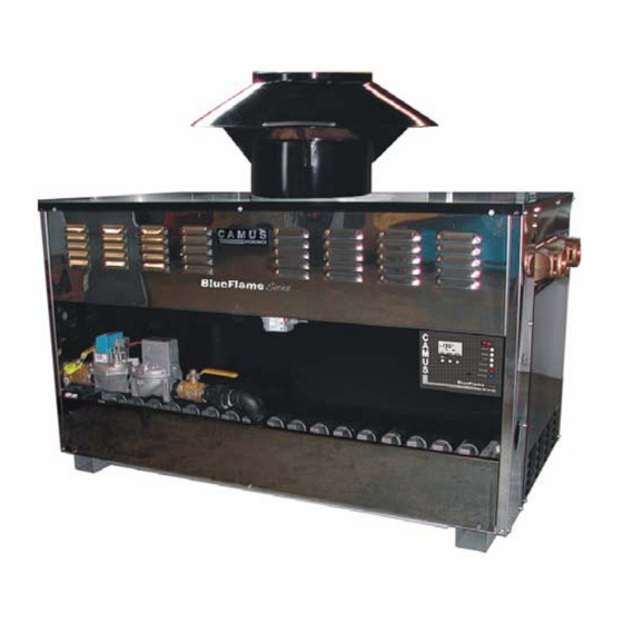
BLUE-FLAME SERIES
FOR HYDRONIC HEATING
1950
HOT WATER SUPPLY
1950
WARNING: If the information in these instructions is not
followed exactly, a fire or explosion may result causing
property damage, personal injury or death
•
•
•
To the installer: After installation, these instructions must
be given to the end user or left on or near the heater.
To the End User: This booklet contains important
information about this heater. Retain for future reference.
HYDRONICS
Do not store or use gasoline or other flammable
vapours and liquids in the vicinity of this or any other
appliance.
WHAT TO DO IF YOU SMELL GAS
o Do not try to light any appliance,
o Do not touch any electrical switch; do not use any
phone in your building,
o Immediately call your gas supplier from a
neighbour's phone. Follow the gas supplier's
instruction,
o If you cannot reach your gas supplier, call the fire
department.
Qualified installer, service agency or the gas supplier
must perform installation and service.
LTD.
99-0030
Rev. 03.00
Advertisement
Table of Contents

Related Manuals for Camus Hydronics BLUE-FLAME Series


Summary of Contents for Camus Hydronics BLUE-FLAME Series
- Page 1 INSTALLATION OPERATION AND SERVICE MANUAL GAS FIRED COMMERCIAL COPPER TUBE BOILERS BLUE-FLAME SERIES FOR HYDRONIC HEATING Models; BFH 480, 660, 840, 1020, 1200, 1380, 1560, 1740, 1950 HOT WATER SUPPLY Models; BFW 480, 660, 840, 1020, 1200, 1380, 1560, 1740,...
-
Page 2: Table Of Contents
Table of Contents INTRODUCTION ..........................1 GENERAL INSTRUCTIONS......................1 BOILER LOCATION ........................2 PROVIDE AIR FOR COMBUSTION AND VENTILATION ............2 ELECTRICAL WIRING ........................3 GAS SUPPLY AND PIPING ......................3 VENTING............................4 SAFETY DEVICES .......................... 7 WATER FLOW SWITCH (shipped loose) .................. 7 LOW WATER CUTOFF (If Equipped) .................. -
Page 3: Introduction
INTRODUCTION Camus Hydronics proudly introduces its Blue-Flame Series of Water Heaters / Hydronic Boilers. These machines are thoughtfully designed for easy operation and maintenance. We are confident that you will come to appreciate the benefits of our product. GENERAL INSTRUCTIONS... -
Page 4: Boiler Location
BOILER LOCATION Install this boiler in a clean, dry location with adequate air supply and close to a good vent connection. Do not locate this boiler in an area where it will be subject to freezing. The boiler must not be installed on carpeting and should be located close to a floor drain in an area where leakage from the boiler or connections will not result in damage to the adjacent area or to lower floors in the structure. -
Page 5: Electrical Wiring
ELECTRICAL WIRING All electrical wiring to the boiler must be electrically bonded to ground in accordance with the requirements of the authority having jurisdiction or, in the absence of such requirements, with the National Electrical Code, ANSI/NFPA 70 or the Canadian Electrical Code Part I, CSA C22.1, Electrical Code. -
Page 6: Venting
1. Outdoor models must be installed outdoors and must use the Air Intake and Vent Cap supplied by Camus Hydronics. Alternately, all listed vent cap may be used along with the Camus supplied air intake 2. Periodically check to ensure that air intake and vent cap are not obstructed. - Page 7 appliance remaining connected to the common venting system placed in operation, while the other appliances remaining connected to the common venting system are not in operation. a) Seal any unused openings in the common venting system. b) Visually inspect the venting system for proper size and horizontal pitch and determine that there is no blockage, restriction, leakage, corrosion or other deficiency, which could cause an unsafe condition.
- Page 8 Three venting options are available for this boiler. See Figure 1 below for details. Standard Venting Outdoor Venting Side View Sidewall Venting Figure 1...
-
Page 9: Safety Devices
SAFETY DEVICES WATER FLOW SWITCH (shipped loose) A water flow switch is shipped loose and is to be installed in the outlet piping on all heating boilers and hot water supply boilers. The flow switch is wired in series with the 24VAC safety control circuit. -
Page 10: Warning Regarding Chilled Water Systems
WARNING REGARDING CHILLED WATER SYSTEMS When a boiler is connected to an air conditioning system where the same water is used for heating and cooling, the chiller must be piped in parallel with the boiler. Appropriate flow control valves; manual or motorized must be provided to prevent the chilled water from entering the boiler. - Page 11 TABLE 2 º º º º º º F (11 C) TEMP F (16.7 C) TEMP F (19.4 C) TEMP RISE RISE RISE Model ΔP ft. ΔP ft. ΔP ft. G.P.M. G.P.M. G.P.M. BF 480 40.0 26.5 22.5 BF 660 55.0 36.5 31.0...
-
Page 12: Placing Boiler In Operation
PLACING BOILER IN OPERATION The Blue-Flame boiler should be installed and started up by qualified personnel. With the boiler off, open makeup water valve and allow system to fill slowly. Adjust the pressure regulator to provide at least 15 psig at the highest point in the system. With all air vents open, run system circulating-pump for a minimum of 30 minutes with the boiler off. - Page 13 Figure 4 • Adjustment procedure. a) Fully open bypass and outlet valves. b) With boiler running, read the inlet temperature after 15 minutes. c) If the inlet temperature is less than 110 ºF slowly close outlet valve until the inlet temperature climbs to 110 ºF d) If the inlet temperature is greater than 110ºF but not greater than 140 ºF no further adjustment is required.
-
Page 14: Instantaneous Water Heater
INSTANTANEOUS WATER HEATER An instantaneous water heater is designed to deliver hot water without the use of a storage tank. It is suitable for applications with variable load such as restaurants, condominiums, apartments and motels. (See figure 5) Call Camus for further recommendations. Figure 5 PILOT AND MAIN BURNER FLAMES To maintain safe operation and the greatest efficiency of the boiler, check the main burner and... - Page 15 Figure 6 If burner characteristics do not match the above, check for accumulation of lint and other foreign material at burner air inlets. A qualified service technician should follow this procedure when burners need cleaning. 1. Shut off power and close main manual gas valve. •...
-
Page 16: 15.2. Pilot Burner
15.2. PILOT BURNER Turn the gas valve control knob counterclockwise to off position and allow the boiler to try for ignition. Observe the spark making sure that it is strong and continuous. If the spark is not acceptable the igniter will have to be removed. This can be readily accomplished by first removing the burners tray assembly from the boiler as detailed in 15.1. -
Page 17: Operation And Service
OPERATION AND SERVICE OPERATION: Before operating the boiler, the entire system must be filled with water, purged of air and checked for leaks. Do not use Stop leak or other boiler compounds. The gas piping must also be leak tested. Any safety devices including low water cutoff, flow switch and high limit used in with this boiler must receive periodic inspection (every six months) to assure proper operation. -
Page 18: Lighting Instructions
LIGHTING INSTRUCTIONS 1. Turn off electric power to boiler. 2. Close main manual valve and main firing valve and wait 5 minutes. 3. Set primary system controller to desired temperature. 4. Set main manual valve to pilot position. 5. Turn on electric power to boiler. The electrode at the pilot should begin to spark. This can be observed with a mirror. -
Page 19: Trouble Shooting Guide
TROUBLE SHOOTING GUIDE SYMPTOM SOLUTION • 1. Power light is not lit when switch is Check wiring to switch. flipped to “ON” • Check circuit breaker • Check fuse 2. Water flow light remains off. • Ensure that pump is running •... -
Page 20: Typical Gas Train
TYPICAL GAS TRAIN ELECTRICAL DIAGRAMS Each Blue-Flame boiler will be provided with its own wiring diagram to guarantee that any options ordered with the unit are properly detailed. The following diagrams 99-5020 and 99-5021 are provided as typical samples only. -
Page 23: Exploded View
EXPLODED VIEW... -
Page 24: Blue Flame Replacement Parts List
BLUE FLAME REPLACEMENT PARTS LIST... -
Page 25: Warranty
HOW TO MAKE A CLAIM Any claim under this warranty shall be made directly to Camus Hydronics Limited Canadian Head Office SERVICE LABOR RESPONSIBILITY Camus shall not be responsible for any labour expenses to service, repair or replace the components supplied. Such costs are the responsibility of the owner. - Page 26 CAMUS Hydronics is a The CAMUS CERTIFIED! manufacturer Seal assures you that replacement parts for Reliability, Efficiency & most copper finned serviceability are built water heaters into every heating single unit! boilers as well more as a information supplier specialty...
Need help?
Do you have a question about the BLUE-FLAME Series and is the answer not in the manual?
Questions and answers