Table of Contents
Advertisement
If the information in these instructions is not followed exactly, a fire or explosion may result causing property damage, personal injury
or death.
•
Do not try to light any appliance,
•
Do not touch any electrical switch; do not use any phone in your building,
•
Immediately call your gas supplier from a neighbour's phone. Follow the gas supplier's instructions,
•
If you cannot reach your gas supplier, call the fire department.
A Qualified installer, service agency or the gas supplier must perform installation and service.
Do not store or use gasoline or other flammable vapours and liquids in the vicinity of this or any other appliance.
TO THE INSTALLER: After installation, these instructions must be given to the end user or left on or near the appliance.
TO THE END USER: This booklet contains important information about this appliance. Retain for future reference.
H
WHAT TO DO IF YOU SMELL GAS
6226 Netherhart Road, Mississauga, Ontario, L5T 1B7
DynaFlame Series
Gas Fired Commercial Copper Tube and Stainless Steel Boilers
Non-Condensing Models DFH/DFW500 thru DFH/DFW6004
Near-Condensing Models DFH/DFW501 thru DFH/DFW6014
Condensing Models DFH/DFW502 thru DFH/DFW6024
HLW
WARNING
WARNING
Installation and Service Manual
99-0435 Rev. 00
Advertisement
Table of Contents

Related Manuals for Camus Hydronics DynaFlame Series


Summary of Contents for Camus Hydronics DynaFlame Series
- Page 1 DynaFlame Series Installation and Service Manual Gas Fired Commercial Copper Tube and Stainless Steel Boilers Non-Condensing Models DFH/DFW500 thru DFH/DFW6004 Near-Condensing Models DFH/DFW501 thru DFH/DFW6014 Condensing Models DFH/DFW502 thru DFH/DFW6024 WARNING If the information in these instructions is not followed exactly, a fire or explosion may result causing property damage, personal injury or death.
- Page 2 6226 Netherhart Road, Mississauga, Ontario, L5T 1B7 99-0435 Rev. 00...
-
Page 3: Table Of Contents
Table of Contents PART 1 GENERAL INFORMATION ........................... 1 OVERVIEW ..............................1 INTRODUCTION ............................1 SPECIAL INSTRUCTIONS TO OWNER ...................... 1 CHECKING EQUIPMENT ..........................2 HOW IT OPERATES (SEQUENCE OF OPERATION) ................. 2 1.6.1 IGNITION PROCESS ............................ 2 1.6.2 HEAT TRANSFER PROCESS ........................3 1.6.3 END OF SEQUENCE ............................ - Page 4 PRIMARY HEAT EXCHANGER ......................... 21 LOW WATER TEMPERATURE SYSTEMS ....................21 INSTANTANEOUS WATER HEATER (non-condensing) ................22 CONDENSER HEAT RECOVERY MODULE (CHRM) ................23 CHRM, FLOW and PRESSURE DROP ...................... 24 4.10 WATER FLOW SWITCH (shipped loose) ....................24 4.11 LOW WATER CUTOFF (If Equipped) ......................
- Page 5 10.8 CONDENSING HEAT RECOVERY MODULE (CHRM) INSPECTION ............65 10.9 RE-INSTALL HEAT EXCHANGERS ......................65 10.10 COMBUSTION AIR FAN ..........................65 10.11 COMBUSTION AND VENTILATION AIR ....................65 10.12 CONTROL CIRCUIT VOLTAGE ......................... 65 10.13 COMBUSTIBLE MATERIALS ........................65 10.14 FREEZE PROTECTION ..........................
-
Page 6: Part 1 General Information
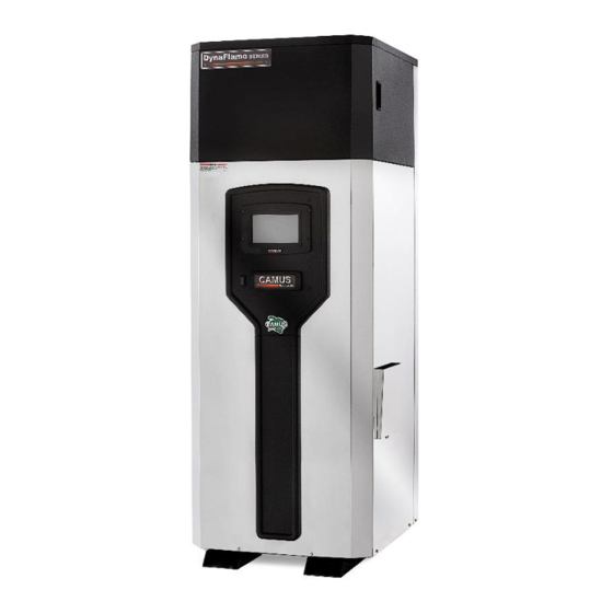
PART 1 GENERAL INFORMATION Figure 1: DynaFlame Non-Condensing OVERVIEW The DynaFlame is available in the following body styles: • 23” x 27” footprint, DynaFlame. As non-condensing 85% efficient, available in models 500, 750, 1100, 1200. As near condensing (DFX) 88% efficient DFX, available in models 501, 751, 1101, 1201. -
Page 7: Checking Equipment
CHECKING EQUIPMENT accelerate preprogrammed rate towards maximum speed using the modulating signal provided by the on board modulating control or the remote Check for signs of shipping damage upon receiving operating system. equipment. Pay particular attention to parts accompanying If temperature high limit, water flow and airflow switches the boiler, which may show signs of being hit or otherwise are closed the fan will run at pre-purge speed until the being mishandled. -
Page 8: Heat Transfer Process
Air/Gas Ratio Control Valve senses the pressure differential between the Combustion Air Fan outlet and Installation and service must be performed by the vent outlet and supplies gas to the orifice and into Camus® qualified factory trained service technicians. the Fan inlet to pre-mix with air. The Gas/Air mixture is forced into the Burner and out of WARNING the Burner Ports under pressure at soft start input rate. -
Page 9: Removal Of Existing Appliance
• Factory warranty shall apply only when the appliance is Use a cold mirror, or the flame of a match or candle. • Test for spillage at the draft control device relief opening installed in accordance with local plumbing and building codes, ordinances regulations,... -
Page 10: Clearance From Combustible Material
flue of Category I installations. When necessary, enough to support the full weight of the heater. consider the use of insulation or corrosion resistant venting material. Maintain minimum specified clearances for adequate • operation. All installations must allow sufficient space for Camus DynaFlame boilers and water heaters are servicing the vent connections, water pipe connections, approved at 85% efficiency which allows the equipment... - Page 11 or any of its components. • If the appliance is installed above the level of the building’s radiation system, a low water cut-off device must be installed above the heat exchanger inlet/outlet connections. Some local codes require the installation of a low water cut-off on all systems •...
- Page 12 Table 3: Appliance Dimensions and Specifications [in.] Water Conn. Water Water Flue Inlet Sec. Width Depth Height Conn. Conn. Model Conn. Inlet Height Height "H" "I" "J" "K" "L" "M" "N" Dia. Grooved "A" "B" "C" Prim. [NPT, "D" "E" "F"...
-
Page 13: Part 2 Air Supply & Venting
must be in accordance with Part 7, Venting of Equipment, PART 2 AIR SUPPLY & VENTING of the National Fuel Gas Code, ANSI Z223.1, or Section 7, Venting of Equipment and Air Supply for Appliances, of the CAN/CGA B149, Installation Codes, or applicable provisions of the local building codes. -
Page 14: Venting Guidelines For Category Iii Venting
equivalent special venting is used. The authorities have location and clearances. jurisdiction must approve venting prior to insulating. • The flue from a Category IIl vent system must have 2.1.5 APPROVED VENTING MATERIALS provisions to properly collect and dispose of any •... -
Page 15: Vent Termination Clearances
4) Single wall, galvanized, stainless steel 2.1.9 AIR INLET DAMPER Single wall vent pipes are to be insulated 5 feet from wall In warmer climates, during cold weather, the use of ducted toward the interior of the building to minimize external outdoor air may result in the formation of condensation on the sweating. -
Page 16: Combined Combustion Air Inlet
2.1.12 COMBINED COMBUSTION AIR INLET Ensure that the drain from the condensate tee is not exposed to freezing temperature. The air inlet pipes from multiple appliances can be combined to a single common connection if the common air inlet pipe CONVENTIONAL VENTING (INDOOR) has a cross sectional area equal to or larger than the total INSTALLATIONS... -
Page 17: Air Required For Combustion And Ventilation
exposure to permanent wave solution, chlorinated waxes OUTDOOR VENTING and cleaners, chlorine, water softening chemicals, carbon tetrachloride, halogen based refrigerants, Freon cleaning The DynaFlame windproof cabinet protects the unit from solvents, hydrochloric acid, cements and glues, masonry weather, when fitted with the factory supplied air intake and washing materials, antistatic fabric softeners, dry cleaning UL approved vent cap (93-0298), it will be self-venting and solvents, degreasing liquids, printing inks, paint removers,... -
Page 18: Location Of A Thruwall Vent Termination
• Install the proper vent pipe to the vent cap (provided by could cause damage or could be detrimental to the Camus Hydronics). operation of regulators, relief valves, or other equipment. • Follow all requirements in the General Venting sections LOCATION OF A “THRUWALL”... -
Page 19: Sidewall Clearance Specifications
2.4.5 SIDEWALL CLEARANCE SPECIFICATIONS Direct Vent Terminal Clearances Canadian Installations US Installations 12” (30 cm) 12” (30 cm) Clearance above grade, veranda, porch, deck, or balcony 6” (15 cm) for appliances <10,000 6” (15 cm) for appliances <10,000 Btuh (3kW) Btuh (3kW) 12”... - Page 20 and serves both dwellings β Permitted only if veranda, porch, deck, or balcony is fully open on a minimum of two sides beneath the floor. * For clearances not specified in ANSI Z223.1/ NFPA 54 or CSA-B149.1. Clearance in accordance with local installation codes and the requirements of the gas supplier Other than Direct Vent Terminal Clearances Canadian Installations...
-
Page 21: Part 3 Gas Connection
3” 2 ½” 3 ½” 3” 4” 3 ½” 3,500 PART 3 GAS CONNECTION 3 ½” 3” 4” 3 ½” 4” 3 ½” 4,000 3 ½” 3” 4” 3 ½” 4” 3 ½” 4,500 Verify that the appliance is supplied with the type gas 4”... -
Page 22: Differential Air Pressure (Df2000 -6004)
Figure 10: DR3500 – 5000 SKP25 Regulating Gas of the pressure difference across the combustion air supply to the burner. The actuator maintains a constant air to gas Valve Actuator &SSOV ratio as the volume of air changes based on the operation of the combustion air fan. -
Page 23: Checking Gas Supply Pressure
technician will void the warranty on the gas valve assembly burner is firing. Immediately repair any leak found in the and the burner. An appliance supplied with a properly sized gas train or related components. DO NOT operate an gas line, properly sized meter and a minimum gas supply appliance with a leak in the gas train, valves or related gas pressure (See Table 8 for minimum allowable inlet gas supply piping... -
Page 24: Gas Train And Controls
• vent line connections from components requiring an external If a second manometer is available it can be connected vent line are provided on the component. These vent line to the appropriate gas ports. Typically the gas signal will connection points may be accessed by removing the top of closely follow the air signal on all models. -
Page 25: Part 4 Water Connection
FREEZE PROTECTION PART 4 WATER CONNECTION • Appliance installations are not recommended outdoors • Check all applicable local heating, plumbing and building in areas where danger of freezing exists unless safety codes before proceeding. precautions are taken. Maintaining a mixture of 50% •... -
Page 26: Inlet And Outlet Connections
startup of the machine followed by ramp up to high fire. This INLET AND OUTLET CONNECTIONS sequence minimizes initial condensation and generates stack temperatures which dry up initial condensation in the vent. • All water connections meet American National Standard Category II machines like the near condensing version Pipe Threads (NPT). -
Page 27: Instantaneous Water Heater (Non-Condensing)
temperature climbs to slightly above the recommended temperature. Table 9: Flow and Pressure Drop at a Given If inlet temperature is greater than the recommended Temperature Rise (Stainless Steel Heat Exchanger) temperature but not greater than 140°F no further 20°F (11.1 °C) 25°F (14°C) Heat adjustment is required. -
Page 28: Condenser Heat Recovery Module (Chrm)
CONDENSER HEAT RECOVERY MODULE This appliance may be installed with conventional, sidewall or vertical venting. Conventional vented appliances operate (CHRM) with negative pressure in the vent pipe and require a special The DynaFlame ALL Stainless Steel CHRM is mounted in a vent adapter to increase the flue outlet diameter. -
Page 29: Chrm, Flow And Pressure Drop
plus the expected snow accumulation above the roof as a factory supplied option on all models. Low water cut-offs penetration height. should be tested every six months. The normally open switch contact of the low water cutoff is to be wired in series with the CHRM, FLOW and PRESSURE DROP flow switch. -
Page 30: Condensing Heat Recovery Module Piping Configurations
the discharge line. The discharge line shall allow complete consider the following: • drainage of the valve and line. Relief valves should be Need to know the required flow (GPM) and pressure manually operated at least once a year. If a relief valve drop for your appliance (see Table 8 or 9) •... -
Page 31: Part 5 Electrical & Controls
PART 5 ELECTRICAL & Maximum CONTROLS Full Load Over Current Voltage Amps Model Requirement Protection [Amperes] [Amperes] 500 - 1200 IT IS EXTREMELY IMPORTANT THAT THIS UNIT BE 1500 - PROPERLY GROUNDED! 2000 ELECTRICAL CONECTIONS 2500 460VAC, 60Hz, 3 3000 Phase Table 11: Minimum Voltage Requirements 3500... -
Page 32: Diffrential Air Pressure Switch
DIFFERENTIAL AIR PRESSURE SWITCH Figure 23: Ignition Module A normally open differential air pressure switch is used to prove operation of the combustion air fan. The pressure switch sensing points are installed at the fan outlet as the air moves into the inlet of the burner. One point measures total pressure (+air) and is connected to a pitot tube facing the flow from the fan paddle wheel. -
Page 33: Error Table
Figure 24: Lockout Condition Safety Annunciation, Remote Operator 24VAC Power, Inlet, Outlet Sensor DHW, Stack Sensor ERROR TABLE The following tables provide a description of all the possible errors with the DynaFlame appliance. Errors can be divided into two groups. Alert errors (will disappear when error is gone) and lockout errors (can only be reset by the RESET button). - Page 34 Table 14: Alert/Hold Codes Description Burner switch turned OFF Burner switch turned ON Invalid subsystem reset request occurred Anti-short Cycle Fan speed not proved LCI off, safety circuit is open Setpoint was overridden due to sensor fault Modulation was overridden due to sensor fault Modulation rate was limited due to outlet limit Modulation rate was limited due to Delta-T limit No Lead Lag slaves available to service demand...
-
Page 35: Part 6 Sola Control Panel
Levels of Access PART 6 SOLA CONTROL PANEL Two levels of access to simplify the use of the boiler. APPLIANCE TEMPERATURE User – Access to general boiler and display settings and CONTROLLER adjustments to the central heating and domestic hot water setpoint. - Page 36 Sequence of Operation Flow Switch = Flow Switch, Low Water Cutoff (if equipped) Gas Pressure Switch = Low gas pressure switch (4.5” w.c., N/O), High gas pressure swtich (14” w.c., N/C) Air Pressure Switch = Blocked flue switch (N/C), Air Proving Switch (N/O)
- Page 37 Modulation: Boiler Inlet, Boiler Fixed Setpoint Operation (Standalone) Description Electrical Connection(s) Programming Instructions • Boiler operates at a fixed 1) Press setpoint 2) Press [CH – Central Heat Configuration] • Modulates on boiler inlet 3) Press the to arrive at Setpoint sensor (default) 4) Select Setpoint source: Local •...
- Page 38 Modulation: Boiler Inlet, Outdoor Reset Operation (Standalone) Description Electrical Connection(s) Programming Instructions • Connect outdoor sensor to System/Outdoor contacts Boiler operates with variable setpoint determind by outdoor Press reset curve Press Outdoor Reset Configuration • Modulates on inlet sensor Press the to arrive at Central Heat (default) Select Enable: Enable...
- Page 39 Modulation: System Sensor, Outdoor Reset Operation (Standalone) NOTE: Outdoor Reset Module (PN: W8735S1000) required Description Electrical Connection(s) Programming Instructions • Connect Remote Operator Boiler operates with variable setpoint determind by outdoor Connect System sensor to System/Outdoor contacts Connect Outdoor Sensor to J3 ECOM connector reset curve •...
- Page 40 4-20mA/ 0-10Vdc Setpoint Operation (Standalone, Lead Lag) Description Electrical Connection(s) Programming Instructions • Boiler operates with variable Press setpoint determined by 4-20mA Press [CH – Central Heat Configuration] incoming signal Press the to arrive at Setpoint • Modulates on boiler inlet sensor Select Setpoint Source = S2 (J8-6) 4-20mA (default) Select 4mA water temperature...
- Page 41 4-20mA/ 0-10Vdc Firing Rate Operation (Standalone, Lead Lag) Description Electrical Connection(s) Programming Instructions • Boiler operates with variable Press setpoint determined by 4-20mA Press [Lead Lag Master Configuration] incoming signal Press [Advanced Settings >] • Modulates on header sensor Press the to arrive at Central Heat •...
- Page 42 Modulation: Boiler Inlet, Fixed Setpoint Operation (Standalone, Lead Lag) Description Electrical Connection(s) Programming Instructions • DHW Sensor/ Stat, if required. Boiler operates at a fixed DHW Press setpoint Inlet Sensor operation • Modulates on boiler inlet sensor Press [DHW – Domestic Hot Water Configuration] (default) Select Demand Switch: Modulation sensor only •...
- Page 44 DF(H,W) Lead Lag Operation Master Boiler Description Electrical Connection(s) Programming Instructions • Master boiler lead lag setup Press Select System Identification & Access Verify MB1 Modbus address = 1 Verify MB2 Modbus address = 1 Select Lead Lag Master Configuration Select Master Enabled = Enabled Fixed Setpoint operation Enter CH Setpoint (Fixed setpoint)
- Page 45 The following steps are performed at the factory and verifying on site will be sufficient: 15) Select Pump Configuration 16) Press [Advanced Options >>] 17) Press the to arrive at Central Heat Pump or DHW Pump 18) On Options: Local burner demand 19) On Options: Local Lead Lag Service Active 20) Force On:...
- Page 46 The following steps are performed at the factory and verifying on site will be sufficient: Select Pump Configuration Press [Advanced Options >>] Press the to arrive at Central Heat Pump or DHW Pump On Options: Local burner demand 10) On Options: Local Lead Lag Service Active 11) Force On: Outlet high limit...
- Page 47 Outdoor Sensor connected to Slave boiler 2 (DRH ONLY) Description Electrical Connection(s) Programming Instructions • Slave Boiler Slave boiler outdoor sensor configuration Press • When done correctly, the outdoor Press [Sensor Configuration] temperature will be shown on the Select S5 (J8-11) Sensor Master boiler Connector Type: 10K NTC Single Non-Safety The control will proceed into a Lockout 2 condition...
- Page 48 Rotation schedule adjustment Description Electrical Connection(s) Programming Instructions • Standard rotation schedule is Press based on equalizing run time on Press [Lead Lag Master Configuration] a 1-hour schedule Press [Advanced Settings >] • To vary the rotation to a fixed Press the to arrive at Algorithms schedule based on (hours, days)
- Page 49 Adjust staging of boilers Description Electrical Connection(s) Programming Instructions • Upon a call for heat the lead Press boiler will fire up to the specified Press [Lead Lag Master Configuration] base load rate (80%). If the Press [Advanced Settings >] temperature is not within Error Press the to arrive at Add Stage...
-
Page 50: Configure Menu
CONFIGURE MENU Use for Lead Lag Master Figure 28: Configure Menu demands Refer to Auto above (Default) Pump Control Refer to above Specify pump Pump Output Pump A contact Post pump time Over run time 1..5 min (Default: 1 min) Use for local ... - Page 51 pump has been activated Displays the number of DHW pump cycles the DHW cycles pump has been activated Displays the number of System cycles the pump system pump cycles has been activated...
-
Page 52: Lead Lag Setup
Burner Control Timing and Rates uratio S2 (J8-6) 4-20mA 4-20mA Input Signal sensor Figure 29: Burner Control Timing and Rates S3S4 (J8- 10K NTC 8, 10) Outlet Sensor dual safety sensor Outdoor Sensor: 10K NTC Standalone boiler or S5 (J8-11) single non- Slave boiler sensor... -
Page 53: Local/Remote Switch
check if: Figure 30: Lead lag Wiring Setup (Left: Master, Right: Slave) An additional boiler is needed Lead lag temp < Lead lag setpoint – Add stage Error threshold Number of boilers remain the same Lead lag temp > Lead lag setpoint – Add stage Error threshold AND Lead lag temp <... -
Page 54: Variable Frequency Drive
Carrier Frequency Stop Method Standard Speed Source Acceleration Time 120 sec Deceleration Time 60 sec Fixed Boost Preset Speed Skip Bandwidth Speed at Minimum Consult factory test Signal sticker Speed at Maximum Consult factory test Signal sticker Fault History View Only Select COM2 tab 51 thru 58 Miscellaneous... -
Page 55: Part 7 Components
7.3 COMBUSTION AIR FAN PART 7 COMPONENTS Figure 33: Fan, Burner, Hot Surface Igniter and Flame HOT SURFACE IGNITER (GLOW BAR) Sensor Arrangement The silicon carbide igniter is inserted directly through the fan flange and held in place by two screws. A hold down bracket as well as sealing gasket above and below the igniter assures a good seal. -
Page 56: Part 8 Field Startup Procedure
at minimum input can be done at the low fire adjustment PART 8 FIELD STARTUP screw by first removing the brass cap. Turning PROCEDURE adjustment screw clockwise will increase CO FIRE TESTING CHECKING THE INSTALLATION • • This boiler is designed for low fire soft start. At the start Inspect the connections for water, gas and electricity. - Page 57 • Figure 34: DF 500 – 1750 Gas Valve Shut power off to the heater and open the firing valve. Switch power back on and allow the burner to fire. Lift top cover to access high fire Ignition should be smooth. Always make adjustments to air/gas ratio adjustment meet the recommended CO levels.
- Page 58 To adjust the low-fire setting (DF 2000 – 6004) Table 16: Inline trim valve setting Figure 37: SKP 55 Gas Valve LP Gas Natural Gas (Propane) Model VFD Hz (High Fire) # of Turns # of Turns Clockwise Clockwise DF 500 3 1/2 2 1/2 DF 750...
-
Page 59: Comissioning Appliance
• At full input, block 50% of the fan inlet opening. The display should show ‘LCI not closed’. If it does not, slowly turn the adjustment on the normally closed blocked flue switch counter clockwise until the blocked flue indicator energizes. •... -
Page 60: Part 9 Trouble Shooting
PART 9 TROUBLE SHOOTING COMPONENT FAILURE MODE ANALYSIS • Two wires interchanged • No effect on safety Incoming Power • Live and Neutral wires are interchanged. • The 24Volts and 120 Volts wired • Breaker on transformer trips Transformer are interchanged •... - Page 61 COMPONENT FAILURE MODE ANALYSIS • The DynaFlame boiler was • Verify that all air has been purged from gas line • Verify that boiler is properly grounded running and flame signal suddenly • Inspect flame sensor and associated wiring. Replace if disappeared.
- Page 62 SYMPTOM FAILURE MODE ANALYSIS • Manual Reset Safety High Limit • Verify that the capillary tube is broken. If this is the case, tripped, outlet temperature in replace Manual Reset High Limit • Verify that the system is full of water and that all air has excess of 210 •...
- Page 63 SYMPTOM FAILURE MODE ANALYSIS • Flame detection is present when no • Verify supply voltage for proper polarity. • Check external wiring for voltage feedback visible signs of a flame exist Flame Detection is • Lockout: 105, 158 • Check internal wiring for proper connections out of Sync •...
- Page 64 Alert 291: Abnormal Recycle: Flame was not on at end of ignition Alert 294: Abnormal Recycle: Flame was lost during Run Alert 324: Abnormal Recycle: Hardware flame bias Alert 377: Abnormal Recycle: Hardware flame bias delta This error occurs when a flame signal is not detected by the flame sensor. A minimum signal of 0.8Vdc must be detected by the flame sensor to prove the flame.
- Page 65 Hold 63: LCI OFF (Load Control Input) Hold 67: ILK OFF (High Limit, Gas Pressure Switch, Air Switch) Alert 303: Abnormal Recycle: ILK off during drive to Purge Alert 304: Abnormal Recycle: ILK off during Measured purge time Alert 305: Abnormal Recycle: ILK off during Drive to Pre-igntion Alert 306, 307: Abnormal Recycle: ILK off during Pre-ignition Alert 308: Abnormal Recycle: ILK off during Main Flame Alert 309: Abnormal Recycle: ILK off during Ignition Period...
- Page 66 Alert 354: Abnormal Recycle Delta-T limit This safety was breached as the inlet and outlet temperature difference exceeded 40 F. This is done to prevent damage to the heat exchanger. Before this error appears, the combustion air blower will slow down in an effort to prevent such an error from occurring.
-
Page 67: Part 10 Maintenance
PART 10 MAINTENANCE CAUTION It is important that all gas appliances to be serviced by a Camus® trained service technician. It is in your own interest and that of safety to ensure that all local codes, and all the “NOTES” and “WARNINGS” in this manual are complied with. -
Page 68: Examine The Venting System
immediately. CAUTION • It is important that all gas appliances to be serviced by a Lifting Flames: Lifting flames can be caused by over Camus® trained service technician. It is in your own firing the burner, excessive primary air or high draft in excess of negative 0.15”... -
Page 69: Burner Maintenance
neutralizer to control the pH of the liquid discharged to a 10.5.1 BURNER REMOVAL AND CLEANING drain system is provided with every condensing appliance. Access to the burner will require the following steps: The neutralizer consists of an industrial grade, non- corrosive plastic reservoir for collection of the condensate. -
Page 70: Re-Installing The Igniter
• Cycle unit and check for proper operation. every 4000 hours of operation and more frequently under • Once proper operation is confirmed replace the top high cycling conditions. This will maintain peak ignition efficiency. cover. • Turn off main electrical power to the appliance. 10.8 CONDENSING HEAT RECOVERY •... -
Page 71: Freeze Protection For A Heating Boiler System (Optional)
freezing point or lower. If freeze protection is not provided for the system, a low ambient temperature alarm is recommended for the mechanical room. Damage to the appliance by freezing is non-warrantable. • Location - Heating boilers, hot water supply boilers or water heaters must be located in a room having a temperature of at least 50ºF (10ºC) •... -
Page 72: Part 11 Installations
valves must be the same diameter as the installed piping. If PART 11 INSTALLATIONS flow control is required, other means of flow control such as globe valve or flow setter should be used. 11.1 HEATING BOILER INSTALLATIONS 11.4 INTERMITTENT PUMP OPERATION The appliance MUST always be installed in a primary/secondary piping system for proper operation. -
Page 73: Domestic Hot Water Heater
Check system for installation of glycol or water treatment Return/Inlet temperature Supply/Outlet where required. Where glycol has been used to maintain the temperature readings on the display should read temperature rise across the appliance confirm that the approximately the same temperatures. recommended flow for pure water has been increased by Turn the hot water heater on and allow time for the 15% and the head loss by 20%. - Page 74 The manufacturer recommends the use of a properly sized thermostatic mixing valve to supply domestic hot water at temperatures less than 140°F (60°C). Storing the water at a higher temperature and thermostatically mixing the water will decrease the size of the storage tank and increase the available quantity of mixed hot water.
-
Page 75: Part 12 Exploded View
PART 12 EXPLODED VIEW... - Page 76 SOLA Control Panel...
- Page 77 DynaFlame Model Name of Part ID Part 14-5214-11A 102752 102753 Lip Protector 14-5214-30A 14-5214-35-50A 14-5315 Bottom 14-5235A Transition Inner to 14-5328 Outer Jacket DF-500-HTX DF-750-HTX DF-1100-HTX DF-1200-HTX DF-1500-HTX DF-1750-HTX DF-2000-HTX Primary Copper/ DF-2500-HTX Copper Nickel Heat Exchanger (V DF-3000-HTX Baffles Included) DF-3500-HTX DF-4000-HTX...
- Page 78 DynaFlame Model Name of Part ID Part 109016 109017 109018 109020 109021 109022 109023 Stainless Steel Primary Heat Exchanger (V 109025 Baffles Included) 109026 109028 109029 109030 109032 109033 109034 13-0026 66-5005 Fan/Air Gas Inlet Adapter 13-0027 66-5011 DF-14-0119 Outside Air DF-14-0120 Intake Housing...
- Page 79 DynaFlame Model Name of Part ID Part 14-1030 Electrical Box 14-1005 14-5008 -05A -07A -11A -11A Combustion Chamber 14-5202 -15A -17A -20A -25A -30A -35A -40A -50A Wrap 14-5302 14-5009A 14-5203-15A-25A Combustion 102711 Top Panel 14-5203-35-50A 14-5303 14-5010-05A 14-5008-07A 102631 Combustion Chamber Door...
- Page 80 DynaFlame Model Name of Part ID Part 14-6012 -05A -07A -11A -11A Outer Jacket 14-5223 -15A -17A -20A -25A -30A -35A -40A -50A Right Panel 14-5323 14-6021 -05A -07A -11A -11A Outer Jacket 14-5224 -15A -17A -20A -25A -30A -35A -40A -50A Rear Panel...
- Page 81 DynaFlame Model Name of Part ID Part 14-6004 Outer Jacket 14-5221 Front Panel 14-5321 13-5052 13-5330 Fan Flange 13-5331 13-5332 13-5333 33-0013 Inlet Outlet Header Rear 33-0014 Gasket 33-0030 1/2 HP 1 HP Electrical 1 1/2 HP Motor 3 HP 5 HP 14-5012A 14-5206A...
- Page 82 DynaFlame Model Name of Part ID Part AF10 Fan Housing AF12 AF15 DF-14-0119 Filter Holder DF-14-0120 DF-14-0121 14-5022A Heat Exchanger 14-5205A Base Support 14-5305 Flue Assembly 14-5290 -05A -11A -11A -11A -17A -17A -30A -30A -30A -35-50A -500A 600A (Non- Condensing) Flue Assembly...
- Page 83 DynaFlame Model Name of Part ID Part Flame Rod PSE-CH5 Hot Surface 271R Igniter View Port TG-94010-040 Glass 14-0350 14-0351 Vee Baffle 14-0352 Sets 14-0354 -15A -17A -20A -25A -30A -35A -40A -50A 14-0353 33-5239 Inlet Outlet 33-5237 Header Top 33-5238 Gasket 33-5240...
- Page 84 DynaFlame Model Name of Part ID Part 33-5218 Burner 33-5224 Flange Red Silicone 33-5227 Gasket 33-5230 V8730C1015 V8730C1023 Valve V8730C1031 Actuator V4734C1002 SKP55 VGG10.404U Valve Body VGD40.065U VGD40.080U V4295A1049 Solenoid Valve V4295A1056 Regulator SKP25 Valve ESV371N01SXB ESV751N01SXB Variable Frequency ESV112N01SXB Drive (Standard) ESV222N02YXB...
- Page 85 DynaFlame Model Name of Part ID Part On/Off Switch ESWR4ABLKBLKAF0 75VA HCT-01J2BB07 Transformer Blocked Flue 8021205256 Switch Differential Pressure NS2-1427-00 Switch Control Box 14-1005-03 Plate Honeywell R7910A1001 SOLA Relay(s) 1649341-8 0-10Vdc ETISO-V Converter T92P7A22-24 24V Contactor Touchscreen S7999D1016 Display Not shown in exploded view Part Recommended spare parts...
-
Page 86: Part 13 Electrical Diagrams
PART 13 ELECTRICAL DIAGRAMS... -
Page 90: Warranty
WARRANTY GENERAL Camus® Hydronics Limited (“Camus®”) extends the following LIMITED WARRANTY to the owner of this appliance, provided that the product has been installed and operated in accordance with the Installation Manual provided with the equipment. Camus® will furnish a replacement for, or at Camus®... - Page 91 Name of Owner Name of Dealer Address Address Model No. Serial No. Date of Date of Initial Installation: Operation: 6226 Netherhart Road, Mississauga, Ontario, L5T 1B7, CANADA...
- Page 92 CAMUS Hydronics is a manufacturer of replacement parts for most copper finned and stainless steel water heaters and heating boilers as well as a supplier of specialty HVAC products. Our service line is open 24 hours, 7 days a week. The CAMUS CERTIFIED seal assures you that Reliability, Efficiency &...
Need help?
Do you have a question about the DynaFlame Series and is the answer not in the manual?
Questions and answers