
Related Manuals for Extreme USB VU4500


Summary of Contents for Extreme USB VU4500
-
Page 1: User Guide
VU4500 DVI + USB 2.0 Extender DVI and USB 2.0 100m Cat 5e/LAN KVM Extender System User Guide... - Page 2 Thank you for purchasing the VU4500 KVM Extender System. Please read this guide thoroughly. FCC Radio Frequency Interference Statement Warning This device complies with FCC Part 15 Subpart B. CE Statement The product meets European Standard EMC EN 55022 Class A, EN 61000, and EN 55024.
-
Page 3: Table Of Contents
Contents Introduction ........................4 Product Contents ..................................4 Requirements ....................................4 About the VU4500 KVM Extender ............................4 Compatibility ....................................5 Local Extender Description and Markings ........................... 6 Remote Extender Description and Markings ........................7 Installation Guide ......................8 Installing the Local Extender Unit ............................8 Installing the Remote Extender Unit ............................ -
Page 4: Introduction
About the VU4500 KVM Extender The product incorporates ExtremeUSB® technology, enabling users to extend their video and USB anywhere on the Local Area Network (LAN). It is designed as a remote desktop or KVM (keyboard, video mouse) extender. -
Page 5: Compatibility
Compatibility The product is compatible with many graphics cards, Operating Systems, and monitors. However, there is no guarantee that all devices are compatible with the product as there are a number of different factors that may impact the operation of the KVM Extender. The product complies with USB 1.1 and USB 2.0 specifications governing the design of USB devices. -
Page 6: Local Extender Description And Markings
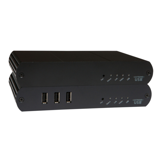
Local Extender Description and Markings The Local Extender connects to the computer using the included DVI and USB cable. Front View Rear View DVI-D In Link 5V DC Config ITEM TYPE DESCRIPTION Pair (Button) Reserved. Used if pairing a Local Extender to a Remote Extender. LED green indicates the system is ready. -
Page 7: Remote Extender Description And Markings
Remote Extender Description and Markings The Remote Extender provides DVI output to a monitor, microphone input, headphone output, and three USB Type A ports for standard USB devices. Additional devices may be connected by attaching USB hubs. Front View Rear View DVI-D Out Link 24V DC... -
Page 8: Installation Guide
Installation Guide Corporate LAN or Network Switch Local Extender Remote Extender USB extension over LAN (The Local Extender and Remote Extender can also be connected in a point-to-point configuration) Before you can install the product, you need to prepare your site: Determine where the computer is to be located and set up the computer. -
Page 9: Checking The Installation
Plug one end of the Cat 5e cabling or patch cord (not included) into the Link port (RJ45) on the Local Extender unit. Plug the other end of the Cat 5e cabling into the corporate LAN port (RJ45) or information outlet near the host computer. -
Page 10: Connecting A Usb Device
Check to see if the USB and Video LEDs are blinking green. If they are not blinking this indicates there is no USB data or Video data. Check the DVI and USB connections to the host computer and the DVI connection to the monitor. - Page 11 PROBLEM CAUSE SOLUTION All LEDs on • The Remote Extender unit 1. Ensure that the DC power adapter is properly Remote Extender isnot receiving power from the connected to the Remote Extender unit. unit are off. Remote Extender DC adapter. 2.
- Page 12 There is no • The USB CMEDIA PNP Audio 1. Check that the CMEDIA device is enumerated on audio. device is not selected as the the host computer. default audio device. 2. If the CMEDIA device is enumerated as an unknown device, there is most likely a driver conflict.
- Page 13 PROBLEM CAUSE SOLUTION All LEDs on both • The USB device is 1. Disconnect the KVM extender product from the Local Extender malfunctioning. the computer. unit and Remote • The computer does not 2. Connect the USB device directly to the USB port Extender unit are recognize the USB device.
-
Page 14: Pairing A Local Extender To A Remote Extender
Pairing a Local Extender to a Remote Extender A Local Extender and Remote Extender comes paired with each other. No additional action is required when you receive your KVM extender. If a Local Extender needs to be paired to a different Remote Extender or a Remote Extender needs to be paired with a different Local Extender, follow these steps to pair a Local Extender to a Remote Extender. -
Page 15: Specifications
Specifications Range 100 meters (330 feet) over a LAN or direct connection over Cat 5e High-speed devices (480 Mb/s) (USB 2.0) USB device support Full speed devices (12 Mb/s) (USB 2.0 & 1.1) Low speed devices (1.5 Mb/s) (USB 2.0 & 1.1) USB hub support Any single chain can include up to 4 USB hubs. -
Page 16: Contacting Technical Support
Contacting Technical Support If you are experiencing problems not referenced in Trouble Shooting, you may contact Technical Support and send the following information: • Host computer make and model • Type of Operating System installed (e.g. Windows XP, Mac OS X, Windows 7 etc.) •... -
Page 17: Technical Glossary
Technical Glossary Category 5e (Cat 5e) Network Cabling Category 5e cable is commonly also referred to as Cat 5e. This cabling is available in either solid or stranded twisted pair copper wire variants and as UTP (Unshielded Twisted Pair) or STP (Shielded Twisted Pair). UTP cables are not surrounded by any shielding making them more susceptible to electromagnetic interference (EMI).
Need help?
Do you have a question about the VU4500 and is the answer not in the manual?
Questions and answers