
Related Manuals for Extreme USB RG2304N


Summary of Contents for Extreme USB RG2304N
-
Page 1: User Guide
USB 2.0 RG2304N/RG2304GE-LAN 4-Port USB 2.0 Gigabit Ethernet LAN Extender Systems User Guide... - Page 2 Thank you for purchasing the USB 2.0 RG2304N/2304GE-LAN. Please read this guide thoroughly. This document applies to Part Numbers: 01-00453, 01-00454, 01-00455, 01-00456, 01-00529, 01-00609, 01-00610, 01-00611, 01-00612, 01-00613, 02-00030, 02-00031, 02-00117 and 02-00118. FCC Radio Frequency Interference Statement Warning This device complies with Part 15 of the FCC rules.
-
Page 3: Table Of Contents
Features ..............................3 The Local Extender ..........................4 The Remote Extender ........................5 Installation Guide ....................6 Installing the RG2304N/2304GE-LAN System on a Local Area Network ......6 Requirements ............................6 Preparing your Network ........................6 Preparing Your Site ..........................7 Installing the Local Extender ...................... -
Page 4: Introduction
• Transparent USB extension • True plug and play; no software drivers required • Works with all major operating systems: Windows®, OS X® and Linux® note USB 3.0 devices will perform at USB 2.0 speeds if extended through the RG2304N/2304GE-LAN. -
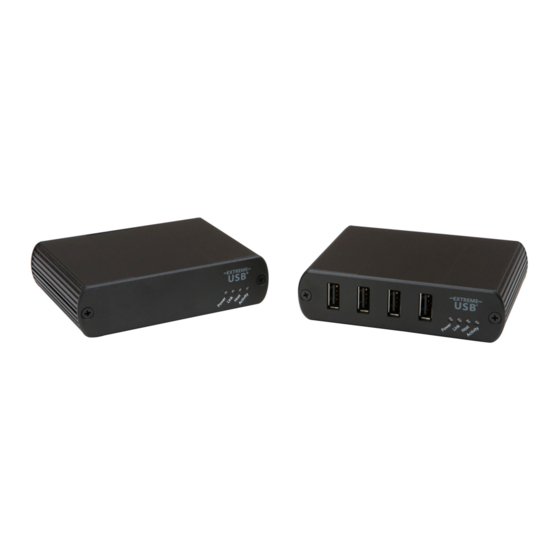
Page 5: The Local Extender
The Local Extender The local extender unit connects to the computer using a standard USB 2.0 cable. Power for this unit is provided by the host computer. Front View Rear View ITEM TYPE DESCRIPTION Power LED LED turns on when power is supplied. (Blue) LED is off when no power is supplied by the host computer. -
Page 6: The Remote Extender
The Remote Extender The remote extender unit provides USB Type A ports for standard USB devices and allows you to connect up to four USB devices directly. Additional devices may be connected by attaching up to four USB hubs to the remote extender unit. -
Page 7: Installation Guide
Pre-installed and configured Local Area Network USB 2.0 is capable of consuming up to 480Mbps. The minimum requirement for using the RG2304N/2304GE-LAN is a Gigabit (1000Base-T) network. The performance of the USB network extension will be limited to the slowest link between the local and the remote extender. -
Page 8: Preparing Your Site
Preparing Your Site Before installing the RG2304N/2304GE-LAN, you will need to prepare your site: Place the computer where desired and set it up. Ensure to locate the USB device(s) within 100m of CAT 5e/6/7 cabling of the switch. Ensure to locate the computer within 100m of CAT 5e/6/7 cabling of the switch. -
Page 9: Installing The Rg2304N/2304Ge-Lan System As Direct Connect
Preparing Your Site Before installing the RG2304N/2304GE-LAN, you will need to prepare your site: Place the computer where desired and set it up. Ensure to locate the USB device(s) within 100m cable-length of the computer. If not, adjust the location of the devices and/or computer accordingly. -
Page 10: Installing The Local Extender
Installing the Local Extender Place the local extender near the computer. Connect the supplied USB cable between the local extender host port and a USB port on the host computer. Connecting the Local Extender to the Remote Extender With Surface Cabling Connect the CAT 5e/6/7 cable into the Link port of the local extender. -
Page 11: Checking The Installation
(see the section on pairing a local and remote Extender). For Windows users (XP, 7, 8, 8.1, 10), open Device Manager to confirm that the RG2304N/2304GE-LAN has been installed correctly. Expand the entry for Universal Serial Bus controllers by clicking the “+”... -
Page 12: Connecting A Usb Device
The following steps apply to both direct connect and network connect configurations for the RG2304N/2304GE-LAN. Ensure the local and remote extenders are either directly connected to each other, or are connected to the same subnet on your network. -
Page 13: Usb Extender Mounting Options
USB Extender Mounting Options The bottoms of the RG2304N/2304GE-LAN enclosures feature four convenient pre-drilled holes for optional mounting. Based on your requirements, choose from two available mounting options: 1. USB Extender Mounting Kit (Purchased separately Order Part #10-00394 USB Mounting Kit - Black 2. -
Page 14: Option 2: Usb Extender Direct Surface Mounting
OPTION 2: USB Extender Direct Surface Mounting (using your own hardware) The bottoms of the RG2304N/2304GE-LAN enclosures features four pre-drilled holes for optional surface mounting. Distance between the enclosure mounting holes: 42.0mm x 77. 0mm mounting hole 1. Mark the center point of each of the four holes on your mounting surface either by directly measuring or using a print out of the stencil below. -
Page 15: Troubleshooting
Troubleshooting The following table provides troubleshooting tips. The topics are arranged in the order in which they should be executed in most situations. If you are unable to resolve the problem after following these instructions, please contact Technical Support for further assistance. PROBLEM CAUSE SOLUTION... - Page 16 PROBLEM CAUSE SOLUTION Link LED on the • The extenders are paired with 1. Wait for a few minutes for the LEDs to go solid. local and the each other but have not yet remote extenders established a link. 2. If LEDs do not go solid, contact your network are blinking slowly.
-
Page 17: Contacting Technical Support
Contacting Technical Support If you are experiencing problems not referenced in the Troubleshooting Guide, contact Technical Support at the company where you purchased this product and provide them with the following information: • Host computer make and mode • Type of operating system installed (e.g. Windows 8.1, Windows 10, OS X 10.11, etc.) •... -
Page 18: Technical Glossary
Extender unit and Remote Extender unit. You may use either the T568A scheme (Table 1) or the T568B scheme (Table 2) for cable termination as the USB 2.0 RG2304N/2304GE-LAN requires all four pairs of the cable. RJ45 connectors are sometimes also referred to as 8P8C connectors. Note that any given cable must be terminated using the same T568 scheme on both ends to operate correctly. -
Page 19: Specifications
Specifications RANGE Direct Connect Up to 100m (330 ft) over solid core CAT 5e/6/7 Network Connect Up to 100m (330 ft) between switches over solid core CAT 5e/6/7 USB DEVICE SUPPORT Maximum Throughput Up to 480Mbps* Traffic Types All Traffic Types Device Types All Device Types Maximum Number...
Need help?
Do you have a question about the RG2304N and is the answer not in the manual?
Questions and answers