Table of Contents
Advertisement
Quick Links
Advertisement
Table of Contents

Related Manuals for Extreme USB USB 2.0 RG2324


Summary of Contents for Extreme USB USB 2.0 RG2324
-
Page 1: User Guide
USB 2.0 RG2324/2344 4-Port USB 2.0 Fiber Optic Extender System User Guide... - Page 2 CE Statement We, Icron Technologies Corporation, declare under our sole responsibility that the USB 2.0 RG2324/2344, to which this declaration relates, is in conformity with European Standards EN 55022, EN 61000 and EN 55024.
-
Page 3: Table Of Contents
Features ..............................3 The Local Extender ..........................4 The Remote Extender ........................5 Installation Guide ....................6 Installing the USB 2.0 RG2324/2344 System ................6 Fiber Optic Link Cabling........................6 Requirements ............................6 Preparing Your Site ..........................6 Installing the Local Extender ......................7 Connecting the Local Extender to the Remote Extender ............ -
Page 4: Introduction
Introduction This guide provides product information for the USB 2.0 RG2324 and 2344 models, installation instructions and troubleshooting guidelines. The instructions in this guide assume a general knowledge of computer installation procedures, familiarity with cabling requirements and some understanding of USB devices. -
Page 5: The Local Extender
The Local Extender The local extender connects to the computer using a standard USB 2.0 cable. Power for this unit is provided by the host computer. Front View Rear View Config Mode Link ITEM TYPE DESCRIPTION Power LED (Blue) LED turns on when power is supplied. LED is off when no power is supplied by the host computer. -
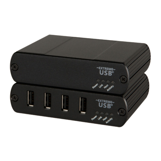
Page 6: The Remote Extender
The Remote Extender The remote extender unit provides USB Type A ports for standard USB devices and allows you to connect up to four USB devices directly. Additional devices may be connected by attaching up to four USB hubs to the remote extender unit. -
Page 7: Installation Guide
Installation Guide Installing the USB 2.0 RG2324/44 System Fiber Optic Link Cabling The local and remote extenders are interconnected by fiber optic cabling. Two strands of multimode fiber cabling is required for the RG2324 for extending up to 500m using 50/125μm or up to 275m using 62.5/125μm. -
Page 8: Installing The Local Extender
Installing the Local Extender Place the local extender near the computer. Connect the supplied USB cable between the local extender host port and a USB port on the host computer. Connecting the Local Extender to the Remote Extender With Surface Cabling: Plug one end of the fiber optic cabling (not included) into the Link port on the local extender. -
Page 9: Connecting A Usb Device
Check that the device is detected and installed properly in the operating system. Compatibility The USB 2.0 RG2324/44 complies with USB 1.1 and USB 2.0 specifications governing the design of USB devices. However, there is no guarantee that all USB devices or hosts will be compatible as there are a... -
Page 10: Optional Usb Extender Mounting Options
Optional USB Extender Mounting Options The bottom of the enclosure features four convenient pre-drilled holes for optional mounting. Based on your requirements, choose from two available mounting options: 1. USB Extender Mounting Kit (Purchased separately Order Part #10-00394 USB Mounting Kit - Black) 2. -
Page 11: Option 2: Usb Extender Direct Surface Mounting
OPTION 2: USB Extender Direct Surface Mounting (using your own hardware) The bottom of the enclosure features four pre-drilled holes for optional surface mounting. Distance between the enclosure mounting holes: 42.0mm x 77. 0mm mounting hole 1. Mark the center point of each of the four holes on your mounting surface either by directly measuring or using a print out of the stencil below. -
Page 12: Troubleshooting
Troubleshooting The following table provides troubleshooting tips. The topics are arranged in the order in which they should be executed in most situations. If you are unable to resolve the problem after following these instructions, please contact Technical Support for further assistance. PROBLEM CAUSE SOLUTION... - Page 13 PROBLEM CAUSE SOLUTION All LEDs on both • The USB device is 1. Disconnect the RG2324/44 from the computer. the local and malfunctioning. remote extenders 2. Connect the USB device directly to the USB port are on, but the USB •...
-
Page 14: Specifications
Specifications RANGE Up to 500m (1,640 ft) over OM2+ multimode fiber USB 2.0 RG2324 Up to 275m (902 ft) over OM1 multimode fiber USB 2.0 RG2344 Up to 10km (6.2 miles) over singlemode fiber USB DEVICE SUPPORT Maximum Throughput Up to 480 Mbps... -
Page 15: Contacting Technical Support
Contacting Technical Support If you are experiencing problems not referenced in the Troubleshooting Guide, contact Technical Support at the company where you purchased this product and provide them with the following information: • Host computer make and mode • Type of operating system installed (e.g. Windows 10, macOS 10.12, etc.) •... -
Page 16: Technical Glossary
Technical Glossary USB 2.0 Cables USB 2.0 cables have two distinct full-sized connectors. The Type A connector is used to connect the cable from a USB device to the Type A port on a computer or hub. The Type B connector is used to attach the USB cable to a USB device.
Need help?
Do you have a question about the USB 2.0 RG2324 and is the answer not in the manual?
Questions and answers