Table of Contents
Advertisement
Advertisement
Table of Contents

Related Manuals for Yaesu FTA-720


Summary of Contents for Yaesu FTA-720
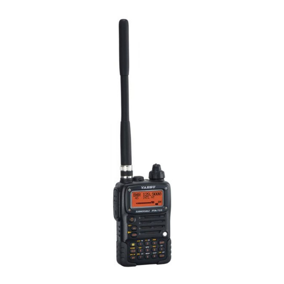
- Page 1 AIR BAND TRANSCEIVER Operating Manual...
-
Page 2: Table Of Contents
ontents Important Notice! ............1 Scanning Operation ........... 23 Introduction ..............2 Basic Scan ................ 23 Control & Connectors ..........3 Channel-Skip Scanning ........... 24 Top Panel ................3 Programmable (Band Limit) Memory Scan (PMS) ..24 Front Panel ................. 4 Dual Watch Operation .......... -
Page 3: Important Notice
FCC RF Exposure Compliance Requirements for Occupational Use Only: The FTA-720 has been tested and complies with the Federal Communications Commission (FCC) RF exposure lim- its for Occupational Use/Controlled exposure environment. In addition, it complies with the following Standards and Guidelines: ... -
Page 4: Introduction
NOAA weather band monitoring, 8-character Alpha/Numeric Display, 70 Memory Channels, and 90 “Book Memory” Channels. We recommend that you read this manual in its entirety, so as to understand the many features of the FTA-720 com- pletely. Keep this manual handy, so you may use it for reference. -
Page 5: Control & Connectors
VOL Knob This control adjusts the audio volume level. Clock- wise rotation increases the volume level. DIAL Selector Knob This 20-position detented rotary switch tunes the operating frequency or selects the memory chan- nels. FTA-720 O perATing AnuAl... -
Page 6: Front Panel
This lamp glows green when a signal is being re- ceived and red when transmitting. You may customize the color setup via the Menu mode. Loudspeaker The internal speaker is located in this position. FTA-720 O perATing AnuAl... -
Page 7: Side Panel
Cable w/Noise Filter or E-DC-6 DC Cable here. Do not connect any wire to this jack if that wire is connected directly to a 28-Volt DC source. Connecting the FTA-720 directly to a source which exceeds 15.0 Volts DC will result in damage to the unit. -
Page 8: Keypad
Split-Memory “Write” Command Activates Split (Duplex) mode. None ( Press + Recalls Menu Item “Step” Third Function Recalls Menu Item “Beep” (for set- Memory “Write” Command (for setting of the synthesizer ( Press and hold key ) ting of the keypad beeper). steps). FTA-720 O perATing AnuAl... - Page 9 ( Press + user via the Menu mode. See page Sets the Memory Skip (Omit) Activates the “Memory Tune” Third Function feature to the current memory mode while in the Memory Recall ( Press and hold key ) channel. mode. FTA-720 O perATing AnuAl...
-
Page 10: Before You Begin
How to Install the Quick Draw Belt Clip The FTA-720 is capable of two-way communica- Connect the hanger to the rear of the FTA-720, with tion on channels used for critical aviation safety the notch pointing directly up, using the supplied communications. -
Page 11: Installation Of Fnb-80Li Battery Pack
FNB-80LI, fol- low the appropriate instructions provided with the charger/battery. Contact your Dealer if you have any doubts about the appropriateness of the particular charger or battery pack you intend to use. FTA-720 O perATing AnuAl... -
Page 12: Installation Of Fba-23 Alkaline Battery Case
23 as shown in the illustration, Alkaline cells. with the Negative [–] side of the If you do not use the FTA-720 for a long time, re- batteries touching the spring con- move the Alkaline batteries from the FBA-23, as nections inside the FBA-23. -
Page 13: Low Battery Indication
Battery” indicator is observed, as this can degrade the charge capacity of your Li-Ion battery pack. Yaesu recommends that you carry an extra, fully- charged pack with you so you will not lose commu- nications capability due to a depleted Li-Ion battery. -
Page 14: Basic Operation
To turn the radio on, as described previously. press and hold in the To attach the supplied antenna to the FTA-720, ( PWR ) Switch for grasp the base of the antenna firmly, and exert a 3 seconds. -
Page 15: Squelch Adjustment
To turn the radio off, press and hold in the current operating band, the entry is ignored (i.e. switch for 3 seconds. FTA-720 does not permit entry of an FM BC band frequency while operating in the AIR band). Squelch Adjustment ... -
Page 16: Accessing The 121.5 Mhz Emergency Frequency
Frequency Throughout this manual, you will see references to sev- eral different frequency setting methods. Each will be The FTA-720 can quickly access the 121.500 MHz particularly useful in a particular operating situation, Emergency Frequency. This function can be activated and they are described below: even when the keypad lock function is in use. -
Page 17: Transmission
BRS ( Business Radio Service ) Memories 22 BRS Channels are pre-programmed at the factory. See page 35 for details of BRS Memory Channel Operation (USA version only). FTA-720 O perATing AnuAl... -
Page 18: Reception Of Weather Channel Broadcasts
( USA version only ) Channels in your area, WX 2 162.4000 MHz the scanner will not stop. The FTA-720 can receive VHF Weather Channel broad- WX 3 162.4750 MHz Press the M O N I TO R WX 4 162.4250 MHz... -
Page 19: Monitor Key
Note: The ANL feature is only activated on the Air To return to normal operation, press the MONITOR key Band. momentarily; the “ ” icon will disappear from the display. FTA-720 O perATing AnuAl... -
Page 20: Lock Function
LOCK Function Beep On/Off The lock function prevents accidental changes to the The FTA-720’s key/button beeper provides convenient frequency setting and the keypad controls. audible feedback whenever a button is pressed. Each key and button has a different beep pitch, and each func- ... -
Page 21: Receive Battery Saver Setup
ABS: Automatic Battery Saver, based on activity on the receiver. An important feature of the FTA-720 is its Receive Bat- tery Saver, which “puts the radio to sleep” for a time The setting of 1:5 will promote the greatest conserva- interval, periodically “waking it up”... -
Page 22: Memory Operation
To label a memory with an alpha/numeric name, the The FTA-720’s Main Memory system allows the user next step is to use the DIAL selector knob to select to store, label, and recall channel frequencies which you any of the 125 available characters (including let- may want to use frequently. -
Page 23: Recalling The Memories
MR mode, you will see the previously-selected were in the “VFO” mode. channel number appearing at the bottom of the “MR” With the FTA-720 in the Memory Recall mode, se- icon on the LCD. lect the desired memory channel. -
Page 24: Deleting Memories
Deleting Memories You may also attach an alpha/numeric name (label) to the “HOME” channel. With the FTA-720 in the Memory mode, rotate the DIAL selector knob to select the memory channel Recall the “HOME” channel, by pressing the you wish to delete. -
Page 25: Scanning Operation
COM band (118.000 - 136.975 MHz); when the scanner reaches the upper- The FTA-720’s automatic scanner is not operational in the most frequency in the COM band, it will revert to the NAV band (108.000 - 117.975 MHz), because the NAV bottom end of the COM band and repeat the scanning stations (ILS, etc.) transmit constantly (thereby causing... -
Page 26: Channel-Skip Scanning
DIAL selector now be limited within the just-programmed range. knob. Note: The PMS feature will not engage if a BRS chan- nel is stored in either the “Lch” or “Uch” memory slot. FTA-720 O perATing AnuAl... -
Page 27: Dual Watch Operation
You may then transmit on the Priority rent channel and the Priority channel will each be polled Channel. for a 500 ms interval, as the FTA-720 looks for activity To stop Dual Watch, press the key followed by on each channel. -
Page 28: Priority Dual Watch Operation
While receiving on the Priority channel, if you momentarily press the PTT switch, Priority Dual Watch will be disabled. You may then transmit on the Priority Channel. To stop Priority Dual Watch, press the key fol- lowed by the key. FTA-720 O perATing AnuAl... -
Page 29: Spectrum Scope Monitor
Analyzer operation. This is normal. Press (or press and hold Note 2: The Spectrum Scope Monitor may not be acti- in) the key to acti- vated on the BRS Memories. vate the Spectrum Scope Monitor. FTA-720 O perATing AnuAl... -
Page 30: Vor Navigation (Air Band)
Vor n aVIgatIon General VOR Equipment NAV BAND ( 108.0000 - 117.9750 MHz ) COM BAND ( 118.0000 - 136.9750 MHz ) VOR MODE CDI MODE COURSE Indicator COURSE Indicator COURSE Deviation Needle “TO” - “FROM” Flag Indicator OVERFLOW Indicator “TO” - “FROM” Flag Indicator FTA-720 O perATing AnuAl... -
Page 31: To Select The Vor Mode
To Select the VOR Mode COURSE Indicator When entering the NAV band (108.000 - 117.975 MHz), the FTA-720 selects the VOR mode automat- ically. The “Course Indicator” will appear on the dis- play, and the “TO” or “FROM” indicator will appear at the right of the “Course Indicator”... -
Page 32: Flying To A Vor Station
Flying to a VOR Station The Aircraft is “ON COURSE” The FTA-720 can indicate the deviation from the direct course to a VOR station. Select a VOR station on your aeronautical chart and turn the DIAL selector knob (or enter the frequency directly with the keypad) to the frequency of the OFF COURSE to the “right” 6 degrees... - Page 33 Vor n aVIgatIon The Aircraft is “ON COURSE” The Aircraft is “OFF COURSE” FTA-720 O perATing AnuAl...
-
Page 34: Entering A Desired Course
Note 2: If the overflow indicator “” appears on the right side, select a heading plus 10 degrees to The FTA-720 can also be configured to indicate the de- the desired course; if the overflow indicator “” viation from the desired course, not only the deviation appears on the left side, select a heading minus 10 from the path to the VOR station. -
Page 35: Position Cross-Checking
VOR mode. The course indicator will show the chart. Your aircraft is located at the point where the course deviation from the VOR radial. Note the ra- lines intersect. dial you currently are on. Cross-checking Position FTA-720 O perATing AnuAl... -
Page 36: Split Operation
” icon will blink, and the transmit frequency will into a memory channel. appear on the display. Now set your radio’s transmit frequency, where the Flight Service Station will be listening for calls, us- ing the DIAL selector knob or keypad. FTA-720 O perATing AnuAl... -
Page 37: Brs (Business Radio Service) Channel Operation
“BRS” (Business Radio Service) appears CTCSS Operation on the display. In the The FTA-720 can be used to silently monitor for calls BRS mode, you will see on busy channels of the BRS band. The CTCSS decoder the previously-selected... - Page 38 We’ll discuss the Digital Code Squelch activated. system shortly. Note: The FTA-720 will not “remember” the CTCSS When you have made your selection of the CTCSS Tone Mode and Tone Frequency. If you would like to Tone Mode, press the...
-
Page 39: Dcs Operation
” icon will appear at the bottom of the display paging than does CTCSS Decoder. The DCS Decoder is when the DCS Decoder is activated. built into your FTA-720, and operation is very similar Note: The FTA-720 will not to that just described for CTCSS Decoder. -
Page 40: Ctcss/Dcs Bell Operation
“ ” icon will blink, the BUSY/TX indicator you may set the FTA-720 up such that a ringing “bell” will flash in sequential colors, and a ringer will sound to sound alerts you to the fact that a call is coming in. Here get your attention. -
Page 41: Miscellaneous Setting
When the APO is activated, the “ ” icon will appear Item “1. T.O.T.” then press the key. at the center bottom on the LCD. If there is no action by Press the key again to enable adjustment of this FTA-720 O perATing AnuAl... -
Page 42: Programming The Key Assignments
The available choices are: making only brief transmissions from your radio, try Activates the Automatic Noise Limiter ANL: setting your FTA-720’s TOT function to time out at one in the AM mode. minute. Exchanges the display locations be-... -
Page 43: Display Customization
When you have made your selection, press the key to save the new setting, then press the PTT key repetitively until the radio exits to normal operation. FTA-720 O perATing AnuAl... -
Page 44: Tx/Busy Indicator Customization
“255,” and you may adjust the display’s red com- ponent until it is just the way you want it. As you make the adjustment, you will be able to see the ef- fects of your changes. FTA-720 O perATing AnuAl... -
Page 45: Changing The Channel Step
The FTA-720 allows you to choose channel steps in the FM broadcast band: 5/10/12.5/15/20/25/50/100 kHz per step. The FTA-720 is set up at the factory to 100 kHz which probably is satisfactory for most operation. How- ever, if you need to change the channel step increments, the procedure to do so is very easy. -
Page 46: Field Programming Mode
To label a memory with an alpha/numeric name, the may want to use frequently by placing the FTA-720 into next step is to use the DIAL selector knob to select the “Field Programming mode.”... -
Page 47: Cpu Resetting
LCD Contrast may be too dark for easy viewing. If so, the LCD Contrast may beeasily adjusted; please follow the in- structions for Set Mode Item “Display Setup 4: Contrast” as described onpages 46 and 48. FTA-720 O perATing AnuAl... -
Page 48: Timer Mode
We do not recommend that any of the default settings be changed, however, until you are thor- 1. Press and hold in the oughly familiar with the operation of the FTA-720. key while tuning the radio on, to activate the Here is the procedure for initiating Menu configuration Timer Mode. -
Page 49: Menu Listing
1. Internal MIC Internal Microphone On/Off. Off / On 2. TEMP Offset Correcting the Thermometer setting. [–22.8 °F (–12.7 °C)] – [+22.8 °F (+12.7 °C)] ([0 °F (50 °C)]) 3. Clock Shift CPU Clock Shift. Off / On FTA-720 O perATing AnuAl... - Page 50 Temp: Indicates the current temperature inside the trans- Default Setting: On ceiver’s case. 4. Contrast Volt: Indicates the battery voltage and battery type. Function: Setting of the display contrast. Available Values: 00 - 15 Default Setting: 06 FTA-720 O perATing AnuAl...
- Page 51 Default Setting: Off Available Values: Individual adjustments of the Red, Green, and Blue color hue may be performed, on a nu- merical scale of “000” to “255.” See page 42 for details. Default Setting: Green (R000, G127, B000) FTA-720 O perATing AnuAl...
- Page 52 Default Setting: 5secs 5secs: The scanner will hold for 5 seconds, then resume whether or not the other station is still transmitting. Busy: The scanner will hold until the signal disappears, then will resume when the carrier drops. FTA-720 O perATing AnuAl...
- Page 53 Note: This Menu Item may only be used on BRS Memory channels (it will not engage on other bands or channels). 10. TONE Set Function: Setting of the CTCSS Tone Frequency. Available Values: 39 standard CTCSS tones. – – – – Default Setting: 67.0Hz FTA-720 O perATing AnuAl...
- Page 54 Available Values: 121.5/HOME Available Values: Off/0.5h/1h/8h Default Setting: 121.5 Default Setting: Off 121.5: Pressing this key instantly recall a 121.5 MHz “Emergency” channel. HOME: Pressing this key instantly recalls a favorite “Home” channel. FTA-720 O perATing AnuAl...
- Page 55 220 °F (105 °C), the radio will disable transmission, to ceiving the Weather Alert Signal allow the radio to cool off. Beep+LED: Sounds a loud beep and illuminates the BUSY/TX lamp when receiving the Weath- er Alert Signal. FTA-720 O perATing AnuAl...
- Page 56 “birdie” should it fall on a desired frequency. Consult Speaker Microphone or an aviation headset con- your Yaesu dealer for details regarding this function. nected via the CT-96 Headset Cable) is in use. In most applications, set this Menu Item to “Off” for proper operation (this disables the internal microphone).
- Page 57 FTA-720 O perATing AnuAl...
- Page 58 –22 °F to +140 °F (–30 °C to +60 °C) Case Size (WxHxD): 2.36” x 3.78” x 1.12” (60 x 96 x 28.5 mm) w/FNB-80LI Weight (approx.): 9.9 oz. (280 grams) with FNB-80LI, antenna Specification are subject to change without notice. FTA-720 O perATing AnuAl...
-
Page 59: Specifications
Better than ±2.5 ppm (–22 °F to 140 °F/–30 °C to +60 °C) Modulation System: AM: Low Level Modulation Spurious Emission: Better than 60 dB below carrier Int. Microphone Type: Condenser Ext. Mic. Impedance: 150 Ohms FTA-720 O perATing AnuAl... -
Page 60: Supplied Accessories
Some accessories are supplied as standard per local requirements, while others may be unavailable in some regions. Consult your Yaesu Dealer for details regarding these and any newly-available options. Connection of any non-Yaesu-approved accessory, should it cause damage, may void the Limited War- ranty on this apparatus. -
Page 61: Accessories & Options
& o ccessorIes ptIons Headset PTT Switch (not supplied) (not supplied) An external PTT switch is required for use with an aviation headset. CT-96 Headset Cable E-DC-5B External Power Cable (Option) FTA-720 O perATing AnuAl... -
Page 62: Troubleshooting
Please confirm the connections and connector sizes are correct. Headset Note: Earphone (speaker) Impedance: 8 or above MIC Impedance: 150 ±20% PTT pressed: Ground PTT not pressed: Open FTA-720 O perATing AnuAl... -
Page 63: Book Memory Channel List
123.000 Air Traffic Control General Use Unicom-Heliports ARTCC 04 136.075 UNICOM 7 123.050 Air Traffic Control General Use Unicom-Heliports ARTCC 05 136.125 UNICOM 8 123.075 Air Traffic Control General Use - - - ARTCC 06 136.150 FTA-720 O perATing AnuAl... - Page 64 STO VMT 127.600 TLV ATIS 132.500 SUNDSVALL VOLMET VIENNA(Schwechat) SDL VMT 127.800 VIE ATIS 122.950 TEL AVIV(BEN GURION RADIO) WARSAW(Okecie) TLV VMT 126.800 WAW ATIS 120.450 VIENNA(VOLMET WIEN AUSTRIA) ZURICH VIE VMT 126.000 ZRH ATIS 128.525 FTA-720 O perATing AnuAl...
- Page 65 FTA-720 O perATing AnuAl...
- Page 66 FTA-720 O perATing AnuAl...
- Page 67 Part 15.21: Changes or modifications to this device not expressly approved by YAESU MUSEN could void the user’s authorization to operate this device.
- Page 68 Copyright 2012 YAESU MUSEN CO., LTD. All rights reserved. YAESU MUSEN CO., LTD. No portion of this manual may be Tennozu Parkside Building 2-5-8 Higashi-Shinagawa, Shinagawa-ku, Tokyo 140-0002 Japan reproduced without the permission of YAESU USA YAESU MUSEN CO., LTD.
Need help?
Do you have a question about the FTA-720 and is the answer not in the manual?
Questions and answers