
Subscribe to Our Youtube Channel
Related Manuals for Advantech PCA-6190


Summary of Contents for Advantech PCA-6190
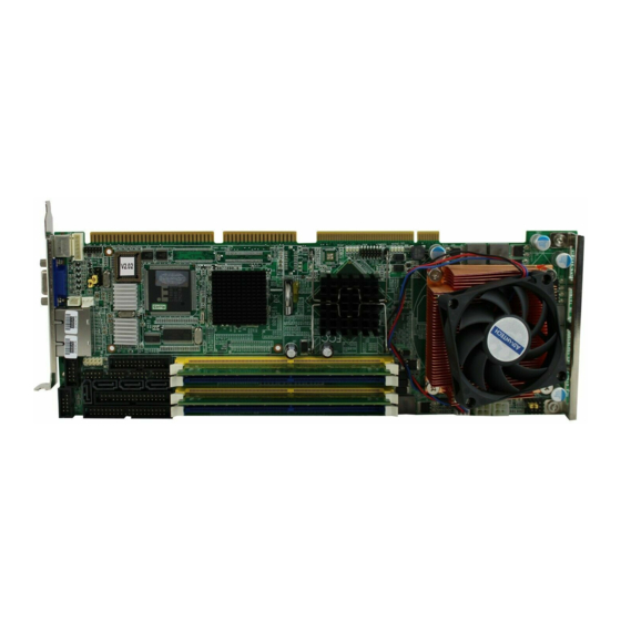
- Page 1 PCA-6190 LGA775 Pentium® 4/Cele- ron® D Processor Card with VGA/Dual Gigabit LAN/HISA/ DVI (800 MHz FSB) User’s Manual...
-
Page 2: Copyright Notice
Copyright Notice This document is copyrighted, 2005, by Advantech Co., Ltd. All rights are reserved. Advantech Co., Ltd. reserves the right to make improve- ments to the products described in this manual at any time without notice. No part of this manual may be reproduced, copied, translated or transmit- ted in any form or by any means without the prior written permission of Advantech Co., Ltd. - Page 3 Advantech equipment is destined for the laboratory or the factory floor, you can be assured that your product will provide the reliability and ease of operation for which the name Advantech has come to be known. Your satisfaction is our primary concern. Here is a guide to Advantech’s customer services.
- Page 4 Table 1.1: Table 1.1: PCA-6190 Comparison Table Model PCA-6190VG- PCA-6190G2- PCA-6190G2- 00A1 00A1 D0A1 VGA: Intel 915 GV integrated VGA controller onboard USB 2.0 port LAN 1: Broadcom BCM5721 10/100/1000Base-T LAN 2: Broadcom BCM5721 10/100/1000Base-T DVI function PCI B-to-B daughter board...
- Page 5 Table 1.2: PCA-6190 DDR memory compatibility table Brand Size Speed Type Part Advan- Memory Number tech PN Apacer 1 GB DDR2 533 DDR2 78.01066. HYB18T5 800AF37 FSS35249 0434 1 GB DDR2 533 DDR2 78.01066. SAM- SUNG K4T51083 QB-ZKD5 512 MB...
-
Page 6: Product Warranty
Advantech assumes no liability under the terms of this warranty as a consequence of such events. If an Advantech product is defective, it will be repaired or replaced at no charge during the warranty period. For out-of-warranty repairs, you will be billed according to the cost of replacement materials, service time and freight. -
Page 7: Initial Inspection
It should be free of marks and scratches and in perfect working order upon receipt. As you unpack the PCA-6190, check it for signs of shipping damage. (For example, damaged box, scratches, dents, etc.) If it is damaged or it fails to meet the specifications, notify our service department or your local sales representative immediately. -
Page 8: Important Safety Information
There is a danger of a new battery exploding if it is incorrectly installed. Do not attempt to recharge, force open, or heat the battery. Replace the battery only with the same or equivalent type recommended by the manufacturer. Discard used bat- teries according to the manufacturer’s instructions. PCA-6190 User’s Manual viii... -
Page 9: Table Of Contents
Jumpers and Connectors............ 6 Table 1.1:Jumpers............6 Table 1.2:Connectors ............6 Board Layout: Jumper and Connector Locations....9 Figure 1.1:Jumper and Connector locations ....9 PCA-6190 Block Diagram ..........10 Figure 1.2: ..............10 Safety Precautions ............11 Jumper Settings ............... 12 1.8.1 How to set jumpers ............ - Page 10 CPU Features ..............35 3.4.2 Hard Disk Boot Priority..........35 3.4.3 Virus Warning............... 36 3.4.4 CPU L1 & L2 Cache............. 36 3.4.5 Hyper-Threading Technology........36 3.4.6 Quick Power On Self Test ..........36 3.4.7 First/Second/Third Boot Device ........36 PCA-6190 User’s Manual...
- Page 11 3.4.8 Boot Other Device ............36 3.4.9 Swap Floppy Drive ............36 3.4.10 Boot Up Floppy Seek............ 36 3.4.11 Boot Up NumLock Status..........36 3.4.12 Gate A20 Option............36 3.4.13 Typematic Rate Setting..........36 3.4.14 Typematic Rate (Chars/Sec) ......... 37 3.4.15 Typematic Delay (msec)..........
- Page 12 PCI/VGA Palette Snoop ..........49 3.8.4 Maximum Payload Size ..........49 PC Health Status.............. 49 Figure 3.11:PC Health Status Screen......49 3.9.1 Case Open Warning ............49 3.9.2 CPU Warning Temperature .......... 50 3.9.3 Current System Temperature ........50 PCA-6190 User’s Manual...
- Page 13 3.9.4 Current CPU Temperature ..........50 3.9.5 CPU FAN Speed............50 3.9.6 System FAN Speed............50 3.9.7 VCORE and Other Voltages......... 50 3.9.8 Shutdown Temperature..........50 3.10 Frequency / Voltage Control ........... 50 Figure 3.12:Spread Spectrum Control screen ....50 3.10.1 CPU Clock Ratio ............
- Page 14 SM Bus Connector (CN29) ........... 109 Table C.19:SM Bus Connector (CN 29)..... 109 C.20 Case Open Connector (CN64)........110 Table C.20:Case Open Connector (CN64) ....110 C.21 Front Panel LAN Indicator connector (CN65)....110 Table C.21:Front Panel LAN Indicator connector (CN65) PCA-6190 User’s Manual...
- Page 15 C.22 GPIO Pin Header (SMD pitch=2.0mm) (CN93)... 111 Table C.22:GPIO pin header (CN93) ......111 C.23 System I/O Ports............111 Table C.23:System I/O ports ........111 C.24 DMA Channel Assignments.......... 112 Table C.24:DMA channel assignments ...... 112 C.25 Interrupt Assignments ........... 112 Table C.25:Interrupt assignments .......
- Page 16 PCA-6190 User’s Manual...
- Page 17 General Information...
-
Page 18: Chapter 1 Hardware Configuration
Chapter 1 Hardware Configuration 1.1 Introduction The PCA-6190 is designed with the Intel 915GV chipset and ICH6 (I/O controller) to support 800 MHz Front side Bus, Intel Pentium 4/Celeron D processor, high speed/high capacity dual channel DDRII 400/533 memory, and high performance I/O functions such as dual Gigabit Ether- net ports, Serial/Parallel ATA ports, and PCI-Express host interface for LAN. -
Page 19: Features
1.2 Features Supports 4 Serial-ATA devices Supports Dual Channel DDRII 400/533 SDRAM up to 4GB Features a thermal protection circuit which will enable the proces- sor to automatically shut down when the cooling system fails. Supports DVI interface (optional) Provides a 14-pin General Purpose I/O interface as the port80 func- tion used in detecting hardware bugs or as the programmable 8-bit I/O. -
Page 20: Specifications
1.3.1 System • CPU: Intel LGA 775 Celeron D up to 3.06GHz, Pentium 4 up to 3.8 GHz, FSB 533/800 MHz. Advantech also certifies several high-perfor- mance CPU coolers as optional parts for customers who use high- speed CPUs in 2U chassis or high temperature environments. -
Page 21: Vga Interface
• ISA bus: Supports ISA without DMA. PCI-to-ISA bridge: ITE IT8888 • AC-97 Audio: PCA-6190 can provide audio function with the optional audio extension module PCA-AUDIO-00A1 • USB port: Supports up to eight USB 2.0 ports with the two USB 2.0 cable kits included, and supports transmission rates up to 480 Mbps;... -
Page 22: Jumpers And Connectors
1.4 Jumpers and Connectors Connectors on the PCA-6190 single board computer link it to external devices such as hard disk drives and a keyboard. In addition, the board has a number of jumpers used to configure your system for your application. - Page 23 Table 1.2: Connectors CN16 Power LED (keyboard lock Suspend: flash flash (ATX/AT) and power LED) System On: ON (ATX/AT) System Off: OFF (AT) System OffL Slow flash (ATX) CN17 External speaker CN18 Reset connector CN19 HDD LED connector CN20 ATX feature connector CN21 ATX soft power switch (PS_ON) CN22...
- Page 24 Notice: The 4-pin ATX 12V power connector "ATX1" must be connected to the power supply to pro- vide adequate power to the CPU card. Other- wise, the system may become unstable. PCA-6190 User’s Manual...
-
Page 25: Board Layout: Jumper And Connector Locations
1.5 Board Layout: Jumper and Connector Locations Figure 1.1: Jumper and Connector locations... -
Page 26: Pca-6190 Block Diagram
1.6 PCA-6190 Block Diagram Intel Pentium 4 LGA 775 Processor DDR II 400/533 Channel A DDR II 400/533 VG A Intel 915GV GMCH DDR II 400/533 CH7307C SD V O Channel B DDR II 400/533 DVI TMDS connector (PCA-6190G2-D0A1 only) -
Page 27: Safety Precautions
Notice: Before install your PCA-6190 into a chassis, make sure that all components on both sides of the CPU card do not touch any metal parts, especially the chassis wall and add-on card at... -
Page 28: Jumper Settings
1.8.2 CMOS clear (J1) The PCA-6190 single board computer contains a jumper that can erase CMOS data and reset the system BIOS information. You can clear CMOS by shorting 2-3 pin while the system is off. Then return to 1-2 pin position. -
Page 29: Watchdog Timer Output (J2)
1.8.3 Watchdog timer output (J2) The PCA-6190 contains a watchdog timer that will reset the CPU or send a signal to IRQ11 in the event the CPU stops processing. This feature means the PCA-6190 will recover from a software failure or an EMI problem. -
Page 30: Cpu Fsb And Memory Speed
1.9.1 CPU FSB and memory speed The PCA-6190 can accept DDRII SDRAM memory chips without parity. Also note: The PCA-6190 accepts DDRII 400MHz SDRAM and DDRII 533MHz SDRAM, depending on the CPU front side bus frequency (FSB). -
Page 31: Processor Installation
1.11 Processor Installation The CPU on the board must have a fan or heat sink attached, to prevent overheating. Warning: Without a fan or heat sink, the CPU will over-heat and cause damage to both the CPU and the single board computer. - Page 32 PCA-6190 User’s Manual...
- Page 33 Connecting Peripherals Chapter 2...
-
Page 34: Chapter 2 Connecting Peripherals
2.2 1st (CN1) IDE Connectors You can attach up to two IDE (Integrated Drive Electronics) drives to the PCA-6190’s built-in controller. The primary (CN1) connector can accommodate two drives. Wire number 1 on the cable is red or blue and the other wires are gray. -
Page 35: Floppy Drive Connector (Cn3)
2.3 Floppy Drive Connector (CN3) You can attach up to two floppy disk drives to the PCA-6190's on board controller. You can use 3.5" (720 KB, 1.44 MB) drives. The single board computer comes with a 34-pin daisy-chain drive con- nector cable. -
Page 36: Usb Ports (Cn6,Cn63,Cn66,Cn67)
1 corresponds to pin 1 of CN4. Pin 1 is on the upper right side of CN4. 2.5 USB Ports (CN6,CN63,CN66,CN67) The PCA-6190 provides up to eight ports of USB (Universal Serial Bus)interface.The USB interface complies with USB Specification Rev. 2.0 support transmission rate up to 480 Mbps and is fuse-protected. The USB interface can be disabled in the system BIOS setup. -
Page 37: Dvi Connector Vcn1 (Optional)
Appendix B. 2.7 DVI Connector VCN1 (optional) The PCA-6190 provides an optional DVI interface that supports DVI dis- play. The user can choose 26-pin to 20-pin DVI cable (p/n: 1700000821) for providing DVI connector. Pin assignments for DVI connector VCN1 are detailed in Appendix B. -
Page 38: Serial Ports (Com1: Cn9/Cn91; Com2: Cn10 )
One 6-pin mini-DIN connectors (CN11) on the card mounting bracket provide connection to a PS/2 keyboard or a PS/2 mouse, respectively. CN11 can also be connected to an adapter cable (P/N: 1700060202, avail- able from Advantech) for connecting to both a PS/2 keyboard and a PS/2 mouse. PCA-6190... -
Page 39: External Keyboard Connector (Cn12)
2.11 External Keyboard Connector (CN12) In addition to the PS/2 mouse/keyboard connector on the PCA-6190's rear plate, there is also an extra onboard external keyboard connector. This gives system integrators greater flexibility in designing their sys- tems. 2.12 CPU Fan Connector (CN68) The PCA-6190 provides 4 pin CPU fan connector. -
Page 40: Front Panel Connectors (Cn16, 17, 18, 19, 21&29)
2.13 Front Panel Connectors (CN16, 17, 18, 19, 21&29) There are several external switches to monitor and control the PCA-6190 2.13.1 Power LED (CN16) CN16 is a 5-pin connector for the power on LED. Refer to Appendix B for detailed information on the pin assignments. If a PS/2 or ATX power supply is used, the system's power LED status will be as indicated below: Table 2.1: PS/2 or ATX power supply LED status... -
Page 41: Reset (Cn18)
2.13.6 SM Bus Connector (CN29) This connector is reserved for Advantech's SNMP-1000 HTTP/SNMP Remote System Manager. The SNMP-1000 allows users to monitor the internal voltages, temperature and fans from a remote computer through an Ethernet network. -
Page 42: Atx Feature Connector (Cn20)
2.14 ATX Feature Connector (CN20) Connect to the CN1 on the Advantech backplane to enable the ATX func- tion, 5V stand-by. 2.15 AC-97 Audio Interface (CN43) The PCA-6190 provides AC-97 audio through PCA-AUDIO-00A1 module from Advantech. 2.16 Serial ATA Interface (SA0,SA1,SA2, and SA3) PCA-6190 User’s Manual... -
Page 43: Connecting To Snmp-1000 Remote Manager
In addition to the one EIDE interfaces (up to two devices), the PCA-6190 provides four high performance serial ATA interfaces (up to 150MB/s) which eases cabling to hard drives with thin and long cables. 2.17 Connecting to SNMP-1000 Remote Manager Use the 6-pin to 8-pin cable to connect the single board computer to SNMP-1000. -
Page 44: Scsi Daughterboard Extension Connector (Cn30)
2.19 SCSI Daughterboard Extension Connector (CN30) The PCA-6190 is equipped with an Adaptec AIC-7899 single-chip PCI- to-SCSI host adapter which provides a dual channel Ultra 160 multitask- ing interface between your computer’s PCI bus and SCSI devices (disk drives, CD-ROM drives, scanners, tape backups, removable media drives, etc.). -
Page 45: Front Panel Lan Indicator Connector (Cn65)
RJ45 on the rear plate. 2.22 GPIO Pin Header (CN93) PCA-6190 particularly has a 14-pin General Purpose I/O interface as the port80 function used in detecting hardware bugs or as the programmable 8-bit I/O. - Page 46 PCA-6190 User’s Manual...
- Page 47 Award BIOS Setup Chapter 3...
-
Page 48: Chapter 3 Award Bios Setup
"CMOS checksum error..." display screen mes- sage appearing. Then enter the "Setup" screen to modify the data. If the "CMOS checksum error..."message appears again and again, please check to see if you need to replace the battery in your system. PCA-6190 User’s Manual... -
Page 49: Entering Setup
3.2 Entering Setup Turn on the computer and press <Del> to enter the BIOS setup. Figure 3.1: Award BIOS Setup initial screen 3.3 Standard CMOS Setup 3.3.1 Date The date format is <week>, <month>, <day>, <year>. 3.3.2 Time The times format in <hour> <minute> <second>, based on the 24-hour military time clock. -
Page 50: Drive A / Drive B
The options are: No Errors/All Errors/All, But Keyboard/All, But Dis- kette/All, But Disk/Key 3.3.6 Memory The category displays base memory, extended memory and total memory detected during POST (Power On Self Test). Figure 3.2: Standard CMOS Features Screen PCA-6190 User’s Manual... -
Page 51: Advanced Bios Features
The “Advanced BIOS Features” screen appears when choosing the “Advanced BIOS Features” item from the “Initial Setup Screen” menu. It allows the user to configure the PCA-6190 according to his particular requirements. Below are some major items that are provided in the Advanced BIOS Features screen. -
Page 52: Hard Disk Boot Priority
3.4.11 Boot Up NumLock Status Set the boot up status Num Lock, the options are "On" and "Off". 3.4.12 Gate A20 Option "Normal": A pin in the keyboard controller controls GateA20. Fast" (Default): Lets chipset control GateA20. PCA-6190 User’s Manual... -
Page 53: Typematic Rate Setting
3.4.13 Typematic Rate Setting The typematic rate is the rate key strokes repeat as determined by the key- board controller. The commands are “Enabled” or “Disabled.” Enabling allows the typematic rate and delay to be selected. 3.4.14 Typematic Rate (Chars/Sec) BIOS accepts the following input values (characters/second) for type- matic rate: 6, 8, 10, 12, 15, 20, 24, 30. -
Page 54: Advanced Chipset Features
By choosing the “Advanced Chipset Features” option from the “Initial Setup Screen” menu, the screen below will be displayed. This sample screen contains the manufacturer’s default values for the PCA-6190, as shown in Figure 3-4: Figure 3.4: Advanced chipset features screen... -
Page 55: Dram Ras# To Cas# Delay
3.5.3 DRAM RAS# to CAS# Delay When the DRAM Timing selectable is set to [Manual], this field is adjust- able. When DRAM is refreshed, the rows and columns are addressed sep- arately. This setup item allows user to determine the timing of the transition from RAS (row address strobe) to CAS (column address strobe). -
Page 56: Pci-Express Root Port Func
Specify the size of system memory to allocate for video memory. 3.5.14 DVMT Memory Size Specify the size of DVMT memory to allocate for video memory. 3.5.15 Init Display First Choose the first display interface to initiate while booting. The choice is "PCI Slot" or "Onboard." PCA-6190 User’s Manual... -
Page 57: Integrated Peripherals
3.6 Integrated Peripherals Figure 3.5: Integrated peripherals Figure 3.6: On-Chip IDE Device 3.6.1 IDE HDD Block Mode If your IDE hard drive supports block mode select Enabled for automatic detection of the optimal number of block read/writes per sector the drive can support. -
Page 58: On-Chip Ide Device
If PATA IDE Mode is set to “Primary,” it will display “P1, P3 Secondary” which means that SATA2 and SATA4 are secondary. If PATA IDE Mode is set to “Secondary,” it will display “P0, P2 Second- ary” which means that SATA1 and SATA3 are secondary. PCA-6190 User’s Manual... -
Page 59: Figure 3.7:Onboard Device
Figure 3.7: Onboard Device 3.6.8 USB Controller Select Enabled if your system contains a Universal Serial Bus (USB) con- troller and you have USB peripherals. The choices: "Enabled," "Dis- abled." 3.6.9 USB 2.0 Controller This entry is to disable/enable the USB 2.0 controller only. The BIOS itself may/may not have high-speed USB support. -
Page 60: Gpio Function
If you want to use a different controller card to connect the floppy disk drives, set this field to Disabled. 3.6.17 Onboard Serial Port 1 The settings are "3F8/IRQ4," "2F8/IRQ3," "3E8/IRQ4," "2E8/ IRQ3," and "Disabled" for the on-board serial connector. PCA-6190 User’s Manual... -
Page 61: Onboard Serial Port 2
3.6.18 Onboard Serial Port 2 The settings are "3F8/IRQ4", "2F8/IRQ3", "3E8/IRQ4", "2E8/ IRQ3" and "Disabled" for the on-board serial connector. 3.6.19 UART Mode Select This item allows you to select UART mode. The choices: "IrDA", "ASKIR", "Normal". 3.6.20 RxD, TxD Active This item allows you to determine the active of RxD, TxD. -
Page 62: Power Management Setup
Figure 3.9: Power management setup screen (1) 3.7.1 Power Supply Type PCA-6190 can support both "ATX" and "AT" power supply. Customers can choose the PSU type through this selection. The choices are: "ATX","AT". While selecting "AT", the ACPI function will disable auto- matically. -
Page 63: Video Off Method
Min Saving Minimum power management., Suspend Mode = 1 hr., and HDD Power Down = 15 min. Max Saving Maximum power management., Suspend Mode = 1 min., and HDD Power Down = 1 min. User Defined Allows you to set each mode individually. When not dis- (Default) abled, each of the ranges are from 1 min. -
Page 64: Poweron By Alarm
Use this to set up the system after power failure. The "Off" will keep the system powered off after power failure, the "On" will boot up the system after failure, and the "Former-Sts" will return the system to the status before power failure. 3.8 PnP/PCI Configurations Figure 3.10: PnP/PCI configurations screen PCA-6190 User’s Manual... -
Page 65: Reset Configuration Data
3.8.1 Reset Configuration Data Default is Disabled. Select Enable to reset Extended System Configura- tion Data (ESCD) if you have installed a new add-on, and system config- uration has caused such a conflict that OS cannot boot. 3.8.2 Resources Controlled By The commands here are "Auto(ESCD)"... -
Page 66: Cpu Warning Temperature
3.9.8 Shutdown Temperature The system will shut down automatically when the CPU temperature is over the selected setting. This function can prevent CPU damage caused by overheating. 3.10 Frequency / Voltage Control Figure 3.12: Spread Spectrum Control screen PCA-6190 User’s Manual... -
Page 67: Cpu Clock Ratio
3.10.1 CPU Clock Ratio Key in a DEC number to set up the CPU Clock Ratio (Min=14; Max=17). This item only shows up in special situations. 3.10.2 Spread Spectrum This setting allows you to reduce the EMI by modulating the signals the CPU generates so that the spikes are reduced to flatter curves. -
Page 68: Save & Exit Setup
This record is required for the system to operate. 3.13 Exit Without Saving Selecting this option and pressing <Enter> lets you exit the setup program without recording any new values or changing old ones. PCA-6190 User’s Manual... - Page 69 Chipset Software Installation Utility Chapter 4...
-
Page 70: Chapter 4 Chipset Software Install Utility
To facilitate the installation of the enhanced display device drivers and utility software, you should read the instructions in this chapter carefully before you attempt installation. The device drivers for the PCA-6190 board are located on the software installation CD. The auto-run function of the driver CD will guide and link you to the utilities and device drivers under a Windows system. -
Page 71: Windows Xp Driver Setup
• Identification of Intel® chipset components in the Device Manager. • Integrates superior video features. These include filtered sealing of 720 pixel DVD content, and MPEG-2 motion compensation for soft- ware DVD Note: This utility is used for the following versions of Windows system, and it has to be installed before installing all the other drivers: Windows 98SE... - Page 72 Click "Next" when you see the following message. Click "Yes" when you see the following message. PCA-6190 User’s Manual...
- Page 73 Click "Next" when you see the following message. When the following message appears, click "Finish" to complete the installation and restart Windows. Chapter 4...
- Page 74 PCA-6190 User’s Manual...
- Page 75 VGA Setup Chapter 5...
-
Page 76: Chapter 5 Vga Setup
3D support deliver an intense and realistic visual experience without requiring a separate graphics card. • Intel Serial Digital Video Output (SDVO): The PCA-6190 provides DVI interface through SDVO ports. It supports CRTs via a VGA con- nector with a maximum pixel lock of 400 MHz (up to 2048x1536 reso- lution @ 85 Hz refresh rate) PCA-6188 User’s Manual... -
Page 77: Windows Xp Driver Setup
5.2 Windows XP Driver Setup Note: Before installing this driver, make sure the CSI utility has been installed in your system. See Chapter 4 for information on installing the CSI utility Insert the driver CD into your system's CD-ROM drive. In a few seconds, the software installation main menu appears, as shown in the following figure. - Page 78 Please click on "Next" to continue the installation You will see a welcome window. Please chick on "Yes" to continue the installation. PCA-6188 User’s Manual...
- Page 79 Click "Finish" to complete the installation and restart the computer now or later. Chapter 5...
- Page 80 PCA-6188 User’s Manual...
- Page 81 LAN Configuration Chapter 6...
-
Page 82: Chapter 6 Lan Configuration
Chapter 6 LAN Configuration 6.1 Introduction The PCA-6190 features single/dual Gigabit Ethernet network interface. With the Broadcom BCM5721 GbE controller designed-in, PCA-6190 implements the PCI Express host interface (PCI-E X1) in LAN connec- tion with the maximum throughput of 2Gbps for heavy-duty industrial network application. -
Page 83: Win Xp Driver Setup (Broadcom Bcm5721)
6.4 Win XP Driver Setup (Broadcom BCM5721) Insert the driver CD into your system's CD-ROM drive. In a few seconds, the software installation main menu appears, as shown in the following figure. Under the "LAN Drivers" heading, click on the "Manual" to open file manager, then click "SETUP.EXE" to run the installation procedure. - Page 84 You will see the license agreement. Please click on "next" to con- tinue the installation. Click "Install" to continue. PCA-6190 User’s Manual...
- Page 85 Click "Finish" to complete the installation. Chapter 6...
- Page 86 PCA-6190 User’s Manual...
- Page 87 USB 2.0 Configuration Chapter 7...
-
Page 88: Chapter 7 Usb 2.0 Configuration
Chapter 7 USB 2.0 Configuration 7.1 Introduction The PCA-6190 is designed with Intel ICH6 which supports both USB1.1 and USB 2.0 high-speed transmission. It remains compatible with today's USB device. High-speed USB 2.0 provides data transfer up to 480Mb/s which is 40 times faster than USB 1.1. It is ideal for today's speed- demanding I/O peripherals. - Page 89 Onboard Security Setup Chapter 8...
-
Page 90: Chapter 8 Onboard Security Setup
Chapter 8 Onboard Security Setup 8.1 Introduction The PCA-6190's hardware monitor is designed with Winbond W83627HF. Onboard security (OBS) functions monitor key hardware. They help you maintain your system's stability and durability. The PCA- 6190 can monitor 5 sets of system positive voltages, 2 sets of system neg- ative voltages, CPU cooling fan speed, and CPU temperature. -
Page 91: Windows Xp Driver Setup
8.2 Windows XP Driver Setup Insert the driver CD into your system's CD-ROM drive. In a few seconds, the software installation main menu appears, as shown in the following figure. Click on the "Install" button under the "OBS DRIVERS" heading. Click "Next"... - Page 92 Click "Next" when you see the following message. Click "Next" when you see the following message. PCA-6190 User’s Manual...
- Page 93 Click "Finish" to complete the installation Click "Finish" when you see the following message. Chapter 8...
-
Page 94: Using The Obs Hardware Doctor Utility
From the desktop of Windows, click on "Start" and select "Pro- gram,” select "Winbond HWDoctor" and click "HWDOCTOR." It is recommended that you load the default values for all the OBS settings. However, if desired, you can establish new conditions for voltage, fan speed, and temperature. PCA-6190 User’s Manual... - Page 95 Chapter 8...
- Page 96 PCA-6190 User’s Manual...
- Page 97 Programming the Watchdog Timer Appendix A...
-
Page 98: Appendix A Programming The Watchdog
Appendix A Programming the watchdog A.1 Programming the Watchdog Timer The PCA-6190's watchdog timer can be used to monitor system software operation and take corrective action if the software fails to function after the programmed period. This section describes the operation of the watchdog timer and how to program it. - Page 99 Unlock W83627H Select register of watchdog timer Enable the function of the watchdog timer Use the function of the watchdog time Lock W83627HF Appendix A...
- Page 100 (hex). This number decides how long the watchdog timer waits for strobe before generating an inter- rupt or reset signal. Writing a new value to this register can reset the timer to count with the new value. PCA-6190 User’s Manual...
-
Page 101: Example Program
F7 (hex) read/write Bit 6: Write 1 to enable key- board to reset the timer, 0 to disable.[default] Bit 5: Write 1 to generate a timeout signal immediately and automatically return to 0. [default=0] Bit 4: Read status of watch- dog timer, 1 means timer is ""time out""."... - Page 102 Enable watchdog timer and set 5 minutes as timeout interval ;----------------------------------------------------------- Mov dx,2eh ; unlock W83627H Mov al,87h Out dx,al Out dx,al ;----------------------------------------------------------- Mov al,07h ; Select registers of watchdog timer Out dx,al Mov al,08h Out dx,al PCA-6190 User’s Manual...
- Page 103 ;----------------------------------------------------------- Dec dx ; Enable the function of watchdog timer Mov al,30h Out dx,al Mov al,01h Out dx,al ;----------------------------------------------------------- Dec dx ; Set minute as counting unit Mov al,0f5h Out dx,al al,dx Or al,08h Out dx,al ;----------------------------------------------------------- Dec dx ; Set timeout interval as 5 minutes and start counting Mov al,0f6h Out dx,al Mov al,5...
- Page 104 Mov al,0f7h Out dx,al al,dx Or al,80h Out dx,al ;----------------------------------------------------------- Dec dx ; lock W83627HF Mov al,0aah Out dx,al Enable watchdog timer to be reset by keyboard ;----------------------------------------------------------- Mov dx,2eh ; unlock W83627H Mov al,87h Out dx,al PCA-6190 User’s Manual...
- Page 105 Out dx,al ;----------------------------------------------------------- Mov al,07h ; Select registers of watchdog timer Out dx,al Mov al,08h Out dx,al ;----------------------------------------------------------- Dec dx ; Enable the function of watchdog timer Mov al,30h Out dx,al Mov al,01h Out dx,al ;----------------------------------------------------------- Dec dx ; Enable watchdog timer to be strobed reset by keyboard Mov al,0f7h Out dx,al al,dx...
- Page 106 Out dx,al ;----------------------------------------------------------- Dec dx ; Generate a time-out signal Mov al,0f7h Out dx,al ;Write 1 to bit 5 of F7 register al,dx Or al,20h Out dx,al ;----------------------------------------------------------- Dec dx ; lock W83627HF Mov al,0aah Out dx,al PCA-6190 User’s Manual...
- Page 107 Programming the GPIO Appendix B...
-
Page 108: Appendix B Programming The Gpio
LOCAL _M_Begin,_M_END,_M_LOP1 _M_Begin: DX,2Eh ; 2E/2F=F1/05 (CR-F1) AL,0F1h =F1/50 (CR-F1) DX,AL ;-Index DX,2Fh al,_M_HL ;AL<--05/50 DX,AL ;-Data DX,2Fh AL,DX ;-Data al,55h _M_LOP1 _M_Begin _M_LOP1: DX,2Fh AL,_M_HL ;AL<-05/50 AL,1 ;05/50 -->0A/A0 DX,AL ;-Data DX,2Fh AL,DX ;-Data al,0AAh _M_END _M_Begin PCA-6190 User’s Manual... - Page 109 _M_END: ENDM ;------------------------------------------------------------ ; Logic_Dev_Sel ;------------------------------------------------------------ Logic_Dev_Sel MACRO Log_Dev DX,2Eh AL,07h ; Point To Logical Device Number Reg. DX,AL DX,2Fh AL,Log_Dev ; Select Logical Device Number 7 DX,AL ; (GAME/MIDI/GPIO Port) ENDM ;------------------------------------------------------------ ;------------------------------------------------------------ AnyKey MACRO AH,01H ENDM ;------------------------------------------------------------ ;------------------------------------------------------------ PRINT MACRO String dx,offset string AH,09H...
- Page 110 ;;Read CR-2A, Set Bit[7:2]=1 AL,0FCh ;;Write Back CR-2A DX,2Fh DX,AL ;;-Data Logic_Dev_Sel 7 dx,2eh ;Logic Device 7 CR-F0(GPIO 10-17) al,0f0h dx,al ;-Index (F0) dx,2fh al,0f0h ; 1=GPI/0=GPO GPIO[7:4]=GPI dx,al ;-Data(F0) GPIO[3:0]=GPO Print MSG_1 MTEST1 05h ;05h=0101B Print MSG_3 AnyKey PCA-6190 User’s Manual...
- Page 111 dx,2eh ;Logic Device 7 CR-F0(GPIO 10-17) al,0f0h dx,al ;-Index (F0) dx,2fh al,0fh ; 1=GPI/0=GPO GPIO[7:4]=GPO dx,al ;-Data(0F) GPIO[3:0]=GPI Print MSG_2 MTEST1 50h ;50h=0101b Print MSG_3 ;------------------------------------------------------------ AH,4CH BEGIN Appendix B...
- Page 112 PCA-6190 User’s Manual...
- Page 113 I/O Pin Assignments Appendix C...
-
Page 114: Appendix C Pin Assignments
Appendix C Pin Assignments C.1 IDE Hard Drive Connector (CN1) Table C.1: IDE hard drive connector (CN1, CN2) Signal Signal IDE RESET* DATA 7 DATA 8 DATA 6 DATA 9 DATA 5 DATA 10 DATA 4 DATA 11 DATA 3 DATA 12 DATA 2 DATA 13... -
Page 115: Floppy Drive Connector (Cn3)
C.2 Floppy Drive Connector (CN3) Table C.2: Floppy drive connector (CN3) Signal Signal FDHDIN* FDEDIN* INDEX* MOTOR 0* DRIVE SELECT 1* DRIVE SELECT 0* MOTOR 1* DIRECTION* STEP* WRITE DATA* WRITE GATE* TRACK 0* WRITE PROTECT* READ DATA* HEAD SELECT* DISK CHANGE* * low active Appendix C... -
Page 116: Parallel Port Connector (Cn4)
C.3 Parallel Port Connector (CN4) Table C.3: Parallel port connector (CN4) Signal Signal STROBE* AUTOFD* INIT* SLCTINI* ACK* BUSY SLCT * low active PCA-6188 User’s Manual... -
Page 117: Usb Connector (Cn6, Cn63, Cn66, Cn67)
C.4 USB Connector (CN6, CN63, CN66, CN67) Table C.4: USB1/USB2 connector (CN6) USB1 Signal USB2 Signal +5 V +5 V Chassis GND N/CA C.5 VGA Connector (CN7) Table C.5: VGA connector (CN7) Signal Signal GREEN BLUE H-SYNC V-SYNC Appendix C... -
Page 118: Vcn1 Dvi Connector
C.6 VCN1 DVI connector Table C.6: VCN5 DVI connector Signal Signal #TMDS1_0 AGP_5V_TMDS2 DDC3_SDAOUT TMDS1_0 #TMDS1_2 #TMDS1_2 TMDS1_2 TMDS1_CK ATI_12C_DAT #TMDS1_1 AGP_5V_TMDS2 ATI_12C_CLK #TMDS1_1 CPIS_ENA_BL DDC3_SCLOUT CPIS_VDD_VCL C.7 COM1/COM2 RS-232 Serial Port (CN9/CN91/CN10) Table C.7: COM1/2 Serial Port (CN9/CN91/CN10) Signal PCA-6188 User’s Manual... -
Page 119: Keyboard And Mouse Connnector (Cn11)
C.8 Keyboard and Mouse Connnector (CN11) Table C.8: Keyboard and mouse connector (CN11) Signal KB DATA MS DATA KB CLOCK MS CLOCK Appendix C... -
Page 120: External Keyboard Connector (Cn68)
C.9 External Keyboard Connector (CN68) Table C.9: External keyboard connector (CN12) Signal DATA C.10 CPU Fan Power Connector (CN14) Table C.10: CPU Fan Power Connector (CN68) Signal +12V FANIO FAMPWM PCA-6188 User’s Manual... -
Page 121: Power Led (Cn16)
C.11 Power LED (CN16) You can use an LED to indicate when the single board computer is on. Pin 1 of CN16 supplies the LED's power, and Pin 3 is the ground. Table C.11: Power LED and keylock conn (CN16) Function LED power (+5 V) C.12 External Speaker Connector (CN17) -
Page 122: Reset Connector (Cn18)
C.13 Reset Connector (CN18) Table C.13: Reset connector (CN18) Signal RESET C.14 HDD LED Connector (CN19) Table C.14: HDD LED connector (CN19) Signal VCC (LED+) IDE LED (LED-) C.15 ATX Feature Connector (CN20) PCA-6188 User’s Manual... -
Page 123: Table C.15:Atx Feature Connector (Cn20)
Table C.15: ATX feature connector (CN20) Signal PS-ON VCCSB C.16 ATX Soft Power Switch (CN21)) Table C.16: ATX soft power switch (CN21) Signal 5VSB PWR-BTN Appendix C... -
Page 124: H/W Monitor Alarm (Cn22)
C.17 H/W Monitor Alarm (CN22) Table C.17: H/W monitor alarm (CN22) Signal Enable OBS alarm Disable OBS alarm PCA-6188 User’s Manual... -
Page 125: Audio Interface (Cn43)
C.18 AC-97 Audio Interface (CN43) Table C.18: AC-97 Audio Interface (CN43) 1 VCC 2 GND 3 SYNC 4 BITCLK 5 SDOUT 6 SDIN0 7 SDIN1 8 AC-RST 9 +12V 10 GND 11 GND 12 N/C C.19 SM Bus Connector (CN29) Table C.19: SM Bus Connector (CN 29) Signal SMB_DATA... -
Page 126: Case Open Connector (Cn64)
C.20 Case Open Connector (CN64) Case Open Connector (CN64) Table C.20: Signal CASEOP# C.21 Front Panel LAN Indicator connector (CN65) Table C.21: Front Panel LAN Indicator connector (CN65) Signal Signal LAN1_LINK N/C LAN2_LINK1000 LAN2_LINK N/C LAN1_LINK100 LAN1_ACT LAN2_LINK100 LAN2_ACT 3VDUAL LAN1_LINK1000 PCA-6188 User’s Manual... -
Page 127: Gpio Pin Header (Smd Pitch=2.0Mm) (Cn93)
C.22 GPIO Pin Header (SMD pitch=2.0mm) (CN93) Table C.22: GPIO pin header (CN93) Signal Signal GPIO_PORT80_1 GPIO_PORT80_5 GPIO_PORT80_3 VCC_GPIO GPIO_PORT80_7 GPIO_PORT80_2 GPIO_PORT80_6 GPIO_PORT80_4 GPIO_PORT80_8 C.23 System I/O Ports Table C.23: System I/O ports Addr. range (Hex) Device 000-01F DMA controller 020-021 Interrupt controller 1, master 022-023... -
Page 128: Dma Channel Assignments
200-207 Game I/O 278-27F Parallel printer port 2 (LPT3) 290-297 On-board hardware monitor 2F8-2FF Serial port 2 300-31F Prototype card 360-36F Reserved 378-37F Parallel printer port 1 (LPT2) 380-38F SDLC, bisynchronous 2 3A0-3AF Bisynchronous 1 3B0-3BF Monochrome display and printer adapter (LPT1) 3C0-3CF Reserved 3D0-3DF... -
Page 129: 1St Mb Memory Map
IRQ9 Cascaded to INT 0A (IRQ 2) IRQ10 Available IRQ11 Available IRQ12 PS/2 mouse IRQ13 INT from co-processor IRQ14 Primary IDE Channel IRQ15 Secondary IDE Channel IRQ3 Serial communication port 2 IRQ4 Serial communication port 1 IRQ5 Parallel port 2 IRQ6 Diskette controller (FDC) IRQ7... - Page 130 PCA-6188 User’s Manual...
Need help?
Do you have a question about the PCA-6190 and is the answer not in the manual?
Questions and answers