
Related Manuals for Advantech PCA-6186


Summary of Contents for Advantech PCA-6186
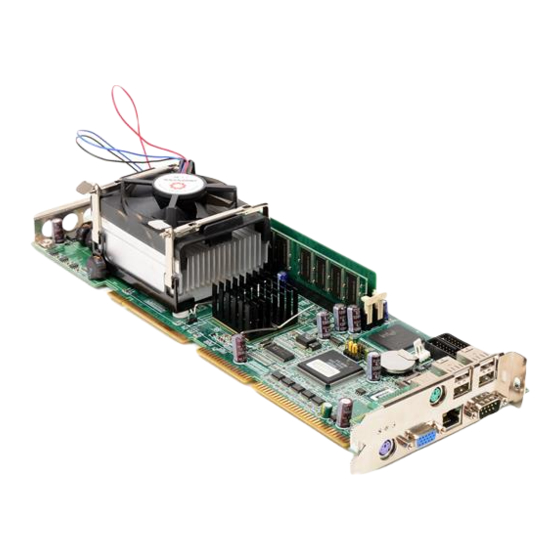
- Page 1 PCA-6186 Full-size socket 478 Intel® Pentium® 4/ Celeron™ processor- based PCI/ISA CPU card User’s Manual...
- Page 2 Copyright Notice This document is copyrighted, 2003, by Advantech Co., Ltd. All rights are reserved. Advantech Co., Ltd. reserves the right to make improve- ments to the products described in this manual at any time without notice. No part of this manual may be reproduced, copied, translated or transmit- ted in any form or by any means without the prior written permission of Advantech Co., Ltd.
- Page 3 Advantech equipment is destined for the laboratory or the factory floor, you can be assured that your product will provide the reliability and ease of operation for which the name Advantech has come to be known. Your satisfaction is our primary concern. Here is a guide to Advantech’s customer services.
- Page 4 PCA-6186 series comparison table Model PCA- PCA- PCA- PCA- PCA- 6186LV- 6186VE- 6186E2- 6186VG- 6186G2- 00A1 00A1 00A1 00A1 00A1 CPU: Single socket 478 Intel® Pentium® 4/ Cele- ron™ Chipset 845GV 845GV 845GV 845GV 845GV Front Side Bus 400/533 400/533...
- Page 5 Advantech assumes no liability under the terms of this warranty as a consequence of such events. If an Advantech product is defective, it will be repaired or replaced at no charge during the warranty period. For out-of-warranty repairs, you will be billed according to the cost of replacement materials, service time and freight.
-
Page 6: Initial Inspection
It should be free of marks and scratches and in perfect working order upon receipt. As you unpack the PCA-6186, check it for signs of shipping damage. (For example, damaged box, scratches, dents, etc.) If it is damaged or it fails to meet the specifications, notify our service department or your local sales representative immediately. -
Page 7: Table Of Contents
Contents Chapter 1 Hardware Configuration .........2 Introduction ............... 2 Features ................3 Specifications ..............4 1.3.1 System................4 1.3.2 Memory................4 1.3.3 Input/Output..............4 1.3.4 VGA interface..............5 1.3.5 Ethernet LAN..............5 1.3.6 Industrial features ............5 1.3.7 Mechanical and environmental specifications....5 Jumpers and Connectors............ - Page 8 Gate A20 Option............32 3.4.9 Typematic Rate Setting..........32 3.4.10 Typematic Rate (Chars/Sec) ......... 32 3.4.11 Typematic Delay (msec)..........32 3.4.12 Security Option ............. 32 3.4.13 APIC Mode ..............32 3.4.14 MPS Version Control For OS........33 PCA-6186 User’s Manual viii...
- Page 9 Advanced Chipset Features..........33 Figure 3.4:Advanced chipset features screen ....33 3.5.1 DRAM Timing Selectable ..........33 3.5.2 CAS Latency Time ............33 3.5.3 Active to Precharge Delay ..........33 3.5.4 DRAM RAS# to CAS# Delay ........34 3.5.5 RAS# Precharge Time ..........34 3.5.6 System BIOS Cacheable..........
- Page 10 6 LAN Configuration ........58 Introduction ..............58 Features ................58 Installation............... 59 Win 98/2K Driver Setup (Intel 82540/82562/82551) ..59 Windows NT Drivers Setup Procedure (Intel 82540)..65 Windows NT Wake-on-LAN Setup Procedure....68 Chapter 7 USB 2.0 Configuration........72 PCA-6186 User’s Manual...
- Page 11 Introduction ..............72 Features ................72 Installation............... 72 Chapter 8 Ultra ATA Storage Driver Setup ....80 Introduction ..............80 Features ................80 Window 2000 Setup Procedure........81 Displaying Driver Information........84 NT Setup Procedure ............85 Chapter 9 Onboard Security Setup ........90 Introduction ..............
- Page 12 PS/2 Mouse Connector (CN33)........121 B.24 AC-97 Audio Interface (CN43)........122 B.25 System I/O Ports............122 B.26 DMA Channel Assignments.......... 123 B.27 Interrupt Assignments ........... 123 B.28 1st MB Memory Map............ 124 B.29 PCI Bus Map ..............124 PCA-6186 User’s Manual...
- Page 13 General Information...
-
Page 14: Chapter 1 Hardware Configuration
478 Pentium 4/Celeron processor (FSB 400/ 533MHz) up to 2.4GHz and above. In addition to high-speed processor, PCA-6186 supports up to 2GB DDR memory with 2 DIMM socket on board. It provides maximum computing power and productivity which is ideal for high-performance demanding application. -
Page 15: Features
1.2 Features Fan status monitoring and alarm: To prevent system overheating and damage, the CPU fan can be monitored for speed and failure. The fan is set for its normal RPM range and alarm thresholds. Temperature monitoring and alert: To prevent system overheat- ing and damage, the CPU card supports processor thermal sensing and auto-protection. -
Page 16: Specifications
1.3 Specifications 1.3.1 System • CPU: PCA-6186 supports Intel Pentium® 4/ Celeron™ up to 2.4GHz and the above, FSB 400/533 MHz. • Firmware hub: Provides security enhancements on computer plat- forms by supporting Random Number Generator (RNG) •... -
Page 17: Vga Interface
PS/2 mouse. An onboard keyboard pin header connector is also avail- able • USB port: Supports up to six USB 2.0 and transmission rate up to 480Mbps. (Six USB ports are available in PCA-6186E2-00A1 and PCA-6186G2-00A1) • ISA driver current: 64 mA (High Drive) 1.3.4 VGA interface •... -
Page 18: Jumpers And Connectors
1.4 Jumpers and Connectors Connectors on the PCA-6186 board link it to external devices such as hard disk drives and a keyboard. In addition, the board has a number of jumpers used to configure your system for your application. The tables below list the function of each of the board jumpers and con- nectors. - Page 19 Table 1.2: Connectors CN19 HDD LED connector CN20 ATX feature connector CN21 ATX soft power switch CN22 HW Monitor Alarm Close: Enable OBS Alarm Open: Disable OBS Alarm CN27 Extension I/O board connector CN28 Extension I/O board connector CN29 SM BUS Connector PIN1: SMB_DATA PIN2: SMB_CLOCK CN31...
-
Page 20: Board Layout: Jumper And Connector Locations
1.5 Board Layout: Jumper and Connector Locations Figure 1.1: Jumper and connector locations PCA-6186 User’s Manual... -
Page 21: Figure 1.2:Extension I/O Dtr Brd (For 6186E2)
Figure 1.2: Extension I/O dtr brd (for 6186E2) Figure 1.3: Extension I/O dtr brd (for6186G2) -
Page 22: Safety Precautions
(often protected by a plastic cover) that slides over the pins to connect them. To “close” (or turn ON) a jumper, you connect the pins with the clip. To “open” (or turn PCA-6186 User’s Manual... -
Page 23: Cmos Clear (J1)
* default setting 1.7.3 Watchdog timer output (J2) The PCA-6186 contains a watchdog timer that will reset the CPU or send a signal to IRQ11 in the event the CPU stops processing. This feature means the PCA-6186 will recover from a software failure or an EMI problem. -
Page 24: System Memory
It will be held low until the watchdog timer is reset. 1.8 System Memory The top-left edge of the PCA-6186 contains two sockets for 184-pin dual in-line memory modules (DIMMs). Both two sockets use 2.5 V unbuf- fered synchronous DRAMs (DDR SDRAM). DIMMs are available in capacities of 64, 128, 256, 512 MB, or 1 GB. -
Page 25: Sample Calculation: Dimm Memory Capacity
1.8.1 Sample calculation: DIMM memory capacity Suppose you install a 512 MB DIMM into your PCA-6186's socket 1 and a 512 MB DIMM into sockets 2. Your total system memory is 1 GB, cal- culated as follows: Table 1.6: DIMM mem capacity sample calculation... -
Page 26: Cache Memory
The cache size in the Intel ® Pentium ® 4 processor is 256/512 KB. In the Celeron CPU, the cache size is 128KB. 1.12 CPU Installation The PCA-6186 is designed for Intel Pentium® 4 processor/Celeron™ (socket 478) Note: Slim Heatsink &... - Page 27 Connecting Peripherals Chapter 2...
-
Page 28: Chapter 2 Connecting Peripherals
2.2 Primary (CN1) and Secondary (CN2) IDE Conn You can attach up to four IDE (Integrated Drive Electronics) drives to the PCA-6186’s built-in controller. The primary (CN1) and secondary (CN2) connectors can each accommodate two drives. Wire number 1 on the cable is red or blue and the other wires are gray. -
Page 29: Floppy Drive Connector (Cn3)
2.3 Floppy Drive Connector (CN3) You can attach up to two floppy disk drives to the PCA-6186's onboard controller. You can use 3.5" (720 KB, 1.44 MB) drives. The card comes with a 34-pin daisy-chain drive connector cable. On one end of the cable is a 34-pin flat-cable connector. -
Page 30: Usb Ports (Cn6, Cn31, And Cn32)
2.5 USB Ports (CN6, CN31, and CN32) The PCA-6186 provides up to six ports of USB (Universal Serial Bus) interface, which gives complete Plug & Play and hot swapping for up to 127 external devices.The USB interface complies with USB Specification Rev. -
Page 31: Serial Ports (Cn9: Com1; Cn10: Com2)
2.8 Serial Ports (CN9: COM1; CN10: COM2) CN9 and CN10 The PCA-6186 offers two serial ports, CN9 as COM1 and CN10 as COM2. These ports can connect to serial devices, such as a mouse or a printer, or to a communications network. -
Page 32: External Keyboard Connector (Cn12)
PS/2 mouse. 2.10 External Keyboard Connector (CN12) CN12 In addition to the PS/2 mouse/keyboard connector on the PCA-6186's ear plate, there is also an extra onboard external keyboard connector. This gives system integrators greater flexibility in designing their systems. -
Page 33: Cpu Fan Connector (Cn14)
2.12 CPU Fan Connector (CN14) CN14 If fan is used, this connector supports cooling fans of 500mA (6W) or less. 2.13 Front Panel Connectors (CN16, 17, 18, 19, 21&22) There are several external switches to monitor and control the PCA- 6186. -
Page 34: External Speaker (Cn17)
2.13.2 External speaker (CN17) CN17 is a 4-pin connector for an extenal speaker. If there is no external speaker, the PCA-6186 provides an onboard buzzer as an alternative. To enable the buzzer, set pins 3-4 as closed 2.13.3 Reset (CN18) Many computer cases offer the convenience of a reset button. -
Page 35: Atx Power Control Connectors (Cn20 And 21)
CN21. 2.14.1 ATX conn (CN20), soft pwr switch conn (CN21) The PCA-6186 can support an advanced soft power switch function if an ATX power supply is used. To enable the soft power switch function: Take the specially designed ATX-to-PS/2 power cable out of the PCA-6186's accessory bag. -
Page 36: Controlling The Soft Power Switch
Users can also identify the current power mode through the system's power LED. 2.15 SM Bus Connector (CN29) This connector is reserved for Advantech's SNMP-1000 HTTP/SNMP Remote System Manager. The SNMP-1000 allows users to monitor the internal voltages, temperature and fans from a remote computer through an Ethernet network. -
Page 37: Audio Interface
2.18 Auxiliary 4-pin power connector (CN46 and CN47) To ensure the sufficiency of power supply for Pentium® 4 CPU card, two auxiliary 4 pin power connector are available in PCA-6186. It is strongly suggested to use auxiliary 4 pin power connector for adequate power sup- ply. - Page 38 PCA-6186 User’s Manual...
- Page 39 Award BIOS Setup Chapter 3...
-
Page 40: Chapter 3 Award Bios Setup
"CMOS checksum error..." display screen mes- sage appearing. Then enter the "Setup" screen to modify the data. If the "CMOS checksum error..."message appears again and again, please check to see if you need to replace the battery in your system. PCA-6186 User’s Manual... -
Page 41: Entering Setup
3.2 Entering Setup Turn on the computer and check for the “patch code”. If there is a number assigned to the patch code, it means that the BIOS supports your CPU. If there is no number assigned to the patch code, please contact Advan- tech’s applications engineer to obtain an up-to-date patch code file. -
Page 42: Standard Cmos Setup
The “Advanced BIOS Features” screen appears when choosing the “Advanced BIOS Features” item from the “Initial Setup Screen” menu. It allows the user to configure the PCA-6186 according to his particular requirements. Below are some major items that are provided in the Advanced BIOS Features screen. -
Page 43: Figure 3.3:Advanced Bios Features Screen
Figure 3.3: Advanced BIOS features screen 3.4.1 Virus Warning If enabled, a warning message and alarm beep activates if someone attempts to write here. The commands are “Enabled” or “Disabled.” 3.4.2 L1 & L2 Cache Enabling this feature speeds up memory access. The commands are “Enabled”... -
Page 44: Boot Up Numlock Status
<Enter> to disable security. When security is disabled, the system will boot, and you can enter Setup freely. 3.4.13 APIC Mode This setting allows selecting an OS with greater than 64MB of RAM. Commands are “Non-OS2” or “OS2.” PCA-6186 User’s Manual... -
Page 45: Mps Version Control For Os
3.5 Advanced Chipset Features By choosing the “Advanced Chipset Features” option from the “Initial Setup Screen” menu, the screen below will be displayed. This sample screen contains the manufacturer’s default values for the PCA-6186, as shown in Figure 3-4: Note:... -
Page 46: Dram Ras# To Cas# Delay
Select the size of Accelerated Graphics Port (AGP) aperture. The aper- ture is a portion of the PCI memory address range dedicated for graphics memory address space. Host cycles that hit the aperture range are for- warded to the AGP without any translation. 3.5.12 On-Chip VGA PCA-6186 User’s Manual... -
Page 47: On-Chip Frame Buffer Size
User can disable onboard VGA controller by selecting "Disabled" 3.5.13 On-Chip Frame Buffer Size User can select frame buffer size. Option is 8MB and 1MB. 3.5.14 Boot Display User can select VGA controller when system is power on. The choice: Auto, PCI, AGP. -
Page 48: Usb Controller
3.6.11 Onboard Serial Port 1 The settings are 3F8H/IRQ4, 2F8H/IRQ3, 3E8H/IRQ4, 2E8H/ IRQ10, and Disabled for the on-board serial connector. 3.6.12 Onboard Serial Port 2 The settings are 3F8H/IRQ4, 2F8H/IRQ3, 3E8H/IRQ4, 2E8H/ IRQ10, and Disabled for the on-board serial connector. PCA-6186 User’s Manual... -
Page 49: Uart Mode Select
3.6.13 UART Mode Select This item allows you to select UART mode. The choices: IrDA, ASKIR, Normal. Figure 3.6: Integrated peripherals (2) 3.6.14 RxD, TxD Active This item allows you to determine the active of RxD, TxD. The Choices: “Hi, Hi,” “Lo, Lo,” “Lo, Hi,” “Hi, Lo.” 3.6.15 IR Transmission Delay This item allows you to enable/disable IR transmission delay. -
Page 50: Epp Mode Select
The power management setup controls the CPU card’s “green” features to save power. The following screen shows the manufacturer’s defaults. Figure 3.7: Power management setup screen (1) 3.7.1 Power-Supply Type Choose AT or ATX power supply 3.7.2 ACPI function The choice: Enabled, Disabled. PCA-6186 User’s Manual... -
Page 51: Power Management
3.7.3 Power Management This category allows you to select the type (or degree) of power saving and is directly related to the following modes: 1. HDD Power Down 2. Suspend Mode There are four selections for Power Management, three of which have fixed mode settings. -
Page 52: Poweron By Modem
LPT port is active. The choice: Enabled, Disabled. 3.7.14 PCI PIRQ [A-D]# When Enabled, the system will resume from suspend mode if interrupt occurs. The choice: Enabled, Disabled. Figure 3.8: Power management setup screen (2) PCA-6186 User’s Manual... -
Page 53: Pnp/Pci Configurations
3.8 PnP/PCI Configurations 3.8.1 PnP OS Installed Select Yes if you are using a plug and play capable operating system. Select No if you need the BIOS to configure non-boot device Figure 3.9: PnP/PCI configurations screen 3.8.2 Reset Configuration Data Default is Disable. -
Page 54: Pc Health Status
Figure 3.10: PC health status screen 3.9.2 Current CPU Temperature This shows you the current CPU temperature. 3.9.3 Current CPUFAN Speed This shows you the current CPUFAN operating speed. 3.9.4 +5V/+12V/-12V/-5V This shows you the voltage of +5V/+12V/-12V/-5V PCA-6186 User’s Manual... -
Page 55: Password Setting
3.10 Password Setting To change the password: Choose the “Set Password” option from the “Initial Setup Screen” menu and press <Enter>. The screen will display the following message: Please Enter Your Password Press <Enter>. If the CMOS is good or if this option has been used to change the default password, the user is asked for the password stored in the CMOS. -
Page 56: Exit Without Saving
3.12 Exit Without Saving Selecting this option and pressing <Enter> lets you exit the setup program without recording any new values or changing old ones. PCA-6186 User’s Manual... - Page 57 Software Installation Utility Chapter 4...
-
Page 58: Chapter 4 Chipset Software Installation Utility
To facilitate the installation of the enhanced display device drivers and utility software, you should read the instructions in this chapter carefully before you attempt installation. The device drivers for the PCA-6186 board are located on the software installation CD. The auto-run function of the driver CD will guide and link you to the utilities and device drivers under a Windows system. -
Page 59: Installing The Csi Utility
• Identification of Intel ® chipset components in the Device Manager. • Integrates superior video features. These include filtered sealing of 720 pixel DVD content, and MPEG-2 motion compensation for soft- ware DVD Note: This utility is used for the following versions of Windows system, and it has to be installed before installing all the other drivers: Windows 98SE... - Page 60 Click "Next" when you see the following message. Click "Yes" when you see the following message. PCA-6186 User’s Manual...
- Page 61 Click "Next" when you see the following message. When the following message appears, click "Finish" to complete the installation and restart Windows. Chapter 4...
- Page 62 PCA-6186 User’s Manual...
- Page 63 VGA Setup Chapter 5...
-
Page 64: Chapter 5 Vga Setup
For example, a 3D application when launched may require more vertex buffer memory to enhance the complexity of objects, or more texture memory to enhance the richness of the 3D environment. PCA-6186 User’s Manual... -
Page 65: Installation
The operating system views the integrated graphics driver as an applica- tion, which uses Direct AGP to request allocation of additional memory for 3D applications, and returns the memory to the operating system when no longer required. The Intel Extreme Graphics Driver determines the size of the pre-allo- cated memory needed and will make additional Non-Local Video Mem- ory requests to achieve the amount needed for the display and application requirement. - Page 66 Windows 2000. For other operating systems, please follow the on-screen installation guide You will see a welcome window. Please chick on "Next" to con- tinue the installation. PCA-6186 User’s Manual...
- Page 67 Click "Yes" when you see the following message. Click on "Yes" to continue the installation Chapter 5...
- Page 68 VGA driver is now installing When the following message appears, you can choose to restart the computer now or later. PCA-6186 User’s Manual...
- Page 69 LAN Configuration Chapter 6...
-
Page 70: Chapter 6 Lan Configuration
Chapter 6 LAN Configuration 6.1 Introduction The PCA-6186 features the 32-bit 10/100/1000 Mbps Ethernet network interface. This interface supports bus mastering architecture and auto- negotiation features. Therefore standard twisted-pair cabling with RJ-45 connectors for 10 Mbps, 100 and 1000 Mbps connections can be used. -
Page 71: Installation
See Chapter 4 for information on installing the CSI utility. The PCA-6186's onboard Ethernet interface supports all major network operating systems. However, the installation procedure varies with differ- ent operating systems. In the following sections, refer to the one that pro- vides driver setup procedure for the operating system you are using. - Page 72 In the "PCI Ethernet Controller Properties" window, select the "Driver" tab. Then click on "Update Driver..." In the "Upgrade Device Driver Wizard" window, click on "Next." PCA-6186 User’s Manual...
- Page 73 In the "Upgrade Device Driver Wizard" window, select "Display for a list of known drivers for this device so that I can choose a spe- cific driver." Then click on "Next." In the following "Upgrade Device Driver Wizard" window, click on Network Adapter and then "Next".
- Page 74 In the "Upgrade Device Driver Wizard" Window, click on "Have Disk" and then "Next". In the following "Upgrade Device Driver Wizard" window, specify the location at "D:\Drv_Lan\82540" for 10/100/1000Base-T or D:\Drv_Lan\82562 for 10/100Base-T Ethernet LAN. D:\Drv_LAN\82540 PCA-6186 User’s Manual...
- Page 75 In the following "Update Device Driver Wizard" window, choose "Intel 82540OEM Based Network Connection" and click on "Next". If your board is with 10/100Base-T Ethernet controller onboard, please choose "Intel 8255x Based Fast Ethernet Version. Chapter 6...
- Page 76 In the following "Update Device Driver Wizard" window, click on "Next" Intel 82540 LAN driver is completed installed. Click on "Finish" to complete the installation. PCA-6186 User’s Manual...
-
Page 77: Windows Nt Drivers Setup Procedure (Intel 82540)
6.5 Windows NT Drivers Setup Procedure (Intel 82540) Note: The CD-ROM drive is designated as "D" throughout this section. From the desktop of Windows NT, click on "Start" and select "Set- tings." Then click on the "Control Panel" icon to select "System." In the "Network"... - Page 78 In the "Select Network Adapter" window, click on "Have Disk..." When the "Insert Disk" window appears, insert the driver CD into the CD-ROM drive and type in D:\Drv_Lan\82540. When you have the correct file path, click on "OK." PCA-6186 User’s Manual...
- Page 79 In the "Select OEM Option" window, select Intel Pro 1000 Family Adapter and click on "OK" In the "Network" window, select the "Adapters" tab. Under "Net- work Adapters," highlight "[1] Intel® PRO/1000MT Network Con- nection Management Adapter" and "[2] Intel® PRO/1000 MT Network Connection."...
-
Page 80: Windows Nt Wake-On-Lan Setup Procedure
Then click on the "Control Panel" icon to select "System." In the "Intel® PROSet" window, under "Select a Network Adapter," choose "Intel® PRO100+ Management Adapter." Then select the "Advanced" tab. Under "Setting," highlight the “Enable PME" item. Under "Value," select "Enabled." Then click on "OK." PCA-6186 User’s Manual... - Page 81 In the "Reboot Required" window, click on "Yes." Chapter 6...
- Page 82 PCA-6186 User’s Manual...
- Page 83 USB 2.0 Configuration Chapter 7...
-
Page 84: Chapter 7 Usb 2.0 Configuration
Chapter 7 USB 2.0 Configuration 7.1 Introduction The PCA-6186 is designed with Intel ICH4 which supports both USB1.1 and USB 2.0 high-speed transmission. It still remains the compatibility with today's USB device. High-speed USB 2.0 provides data transfer up to 480Mb/s which is 40 times faster than USB 1.1. It is ideal for today's speed-demanding I/O peripherals. - Page 85 1. From Windows 2000, select Start and click on Setting. In the window of Setting, click on icon System. Choose the option "Hardware", and then click on "Device Man- ager" Chapter 7...
- Page 86 In Device Manager, choose "USB Controller" and then double click. Choose the option "Driver" and then click on "Update Driver". PCA-6186 User’s Manual...
- Page 87 In Upgrade Device Driver Wizard, click on "Next". In Upgrade Device Wizard, choose "search for a suitable device for my driver" and then click on " Next". Chapter 7...
- Page 88 Tick "Specify a location" and click "Next" In the following windows, please specify the location "D:\Drv_USB\w2k" and then click on "OK". PCA-6186 User’s Manual...
- Page 89 In the following window, please click on "Finish" to complete USB driver installation. Chapter 7...
- Page 90 PCA-6186 User’s Manual...
- Page 91 Ultra ATA Storage Driver Setup Chapter 8...
-
Page 92: Chapter 8 Ultra Ata Storage Driver Setup
ATA controller cable, where one is the master and the other the slave, without restricting transfer mode to PIO-only for both devices. • Technical details of the ATA subsystem can be viewed via use of the application. • Drivers are optimized. PCA-6186 User’s Manual... -
Page 93: Window 2000 Setup Procedure
8.3 Window 2000 Setup Procedure Note: Before installing this driver, make sure the CSI utility has been installed in your system. See Chapter 4 for information on installing the CSI utility. Insert the driver CD into your system's CD-ROM drive. In a few seconds, the software installation main menu appears, as shown in the following figure. - Page 94 Click on "Next" when you see the following message. When you see the following message, click on "Yes" to accept the License Agreement. PCA-6186 User’s Manual...
- Page 95 Click on "Next" when you see the following message. When the following message appears, click "Finish" to complete the installation and restart Windows. Chapter 8...
-
Page 96: Displaying Driver Information
8.4 Displaying Driver Information From the desktop of Windows, click on "Start" and select "Pro- grams." Then select "Intel Ultra ATA Storage Driver" and then "Companion." Click on the "Device Parameters" or the "Storage Report" tab to view related information. PCA-6186 User’s Manual... -
Page 97: Nt Setup Procedure
8.5 NT Setup Procedure Insert the driver CD into your system's CD-ROM drive. In a few seconds, the software installation main menu appears, as shown in the following figure. Under the "IDE DRIVERS" heading, click on the "Install" button. Chapter 8... - Page 98 Click on "Next" when you see the following message. When you see the following message, click on "Yes" to accept the License Agreement. PCA-6186 User’s Manual...
- Page 99 When the following message appears, click "Finish" to complete the installation and restart Windows. Chapter 8...
- Page 100 PCA-6186 User’s Manual...
- Page 101 Onboard Security Setup Chapter 9...
-
Page 102: Onboard Security Setup
The PCA-6186's hardware monitor is designed with Winbond W83782D. Onboard security (OBS) functions monitor key hardware. They help you maintain your system's stability and durability. The PCA-6186 can moni- tor 5 sets of system positive voltages, 2 sets of system negative voltages, CPU cooling fan speed, and CPU temperature. -
Page 103: Windows 9X Drivers Setup Procedure
9.2 Windows 9X Drivers Setup Procedure Insert the driver CD into your system's CD-ROM drive. In a few seconds, the software installation main menu appears, as shown in the following figure. Click on the "WIN 9X" button under the "OBS DRIVERS" heading. When you will see the following message, make sure you have closed all other programs, then click on "OK."... - Page 104 Click on the square graphics button when you see the following message. When you see the following message, click on "OK" to complete the installation. PCA-6186 User’s Manual...
-
Page 105: Windows 2000/Nt Drivers Setup Procedure
9.3 Windows 2000/NT Drivers Setup Procedure Insert the driver CD into your system's CD-ROM drive. In a few seconds, the software installation main menu appears, as shown in the following figure. Click on the "WIN NT" button under the "OBS DRIVERS" heading. Chapter 9... - Page 106 Click "Next" when you see the following message. Click "Next" when you see the following message. PCA-6186 User’s Manual...
- Page 107 Click "Next" when you see the following message. Click "Finish" when you see the following message. Chapter 9...
-
Page 108: Using The Obs Hardware Doctor Utility
This icon is the "Terminate and Stay Resident" (TSR) icon. It will permanently remain in the bottom window bar, and will activate warning signals when triggered by the onboard security system. You can view or change values for various OBS settings by running this utility: PCA-6186 User’s Manual... - Page 109 From the desktop of Windows, click on "Start" and select "Pro- grams" and then "OBS Hardware Doctor." It is recommended that you load the default values for all the OBS settings. However, if desired, you can establish new conditions for voltage, fan speed, and temperature.
- Page 110 PCA-6186 User’s Manual...
- Page 111 Programming the Watchdog Timer Appendix A...
-
Page 112: Appendix A Programming The Watchdog Timer
Appendix A Programming the watchdog timer A.1 Programming the Watchdog Timer The PCA-6186's watchdog timer can be used to monitor system software operation and take corrective action if the software fails to function after the programmed period. This section describes the operation of the watchdog timer and how to program it. - Page 113 Unlock W83627H Select register of watchdog timer Enable the function of the watchdog timer Use the function of the watchdog time Lock W83627HF Appendix A...
- Page 114 (hex). This number decides how long the watchdog timer waits for strobe before generating an inter- rupt or reset signal. Writing a new value to this register can reset the timer to count with the new value. PCA-6186 User’s Manual...
-
Page 115: Example Program
F7 (hex) read/write Bit 6: Write 1 to enable key- board to reset the timer, 0 to disable.[default] Bit 5: Write 1 to generate a timeout signal immediately and automatically return to 0. [default=0] Bit 4: Read status of watch- dog timer, 1 means timer is ""time out""."... - Page 116 Enable watchdog timer and set 5 minutes as timeout interval ;----------------------------------------------------------- Mov dx,2eh ; unlock W83627H Mov al,87h Out dx,al Out dx,al ;----------------------------------------------------------- Mov al,07h ; Select registers of watchdog timer Out dx,al Mov al,08h Out dx,al PCA-6186 User’s Manual...
- Page 117 ;----------------------------------------------------------- Dec dx ; Enable the function of watchdog timer Mov al,30h Out dx,al Mov al,01h Out dx,al ;----------------------------------------------------------- Dec dx ; Set minute as counting unit Mov al,0f5h Out dx,al al,dx Or al,08h Out dx,al ;----------------------------------------------------------- Dec dx ; Set timeout interval as 5 minutes and start counting Mov al,0f6h Out dx,al Mov al,5...
- Page 118 Mov al,0f7h Out dx,al al,dx Or al,80h Out dx,al ;----------------------------------------------------------- Dec dx ; lock W83627HF Mov al,0aah Out dx,al Enable watchdog timer to be reset by keyboard ;----------------------------------------------------------- Mov dx,2eh ; unlock W83627H Mov al,87h Out dx,al PCA-6186 User’s Manual...
- Page 119 Out dx,al ;----------------------------------------------------------- Mov al,07h ; Select registers of watchdog timer Out dx,al Mov al,08h Out dx,al ;----------------------------------------------------------- Dec dx ; Enable the function of watchdog timer Mov al,30h Out dx,al Mov al,01h Out dx,al ;----------------------------------------------------------- Dec dx ; Enable watchdog timer to be strobed reset by keyboard Mov al,0f7h Out dx,al al,dx...
- Page 120 Out dx,al ;----------------------------------------------------------- Dec dx ; Generate a time-out signal Mov al,0f7h Out dx,al ;Write 1 to bit 5 of F7 register al,dx Or al,20h Out dx,al ;----------------------------------------------------------- Dec dx ; lock W83627HF Mov al,0aah Out dx,al PCA-6186 User’s Manual...
- Page 121 I/O Pin Assignments Appendix B...
-
Page 122: Appendix B Pin Assignments
DATA 0 DATA 15 SIGNAL GND DISK DMA REQUEST IO WRITE IO READ IO CHANNEL READY HDACKO* IRQ14 ADDR 1 ADDR 0 ADDR 2 HARD DISK SELECT 0* HARD DISK SELECT 1* IDE ACTIVE* * low active PCA-6186 User’s Manual... -
Page 123: Floppy Drive Connector (Cn3)
B.2 Floppy Drive Connector (CN3) Table B.2: Floppy drive connector (CN3) Signal Signal FDHDIN* FDEDIN* INDEX* MOTOR 0* DRIVE SELECT 1* DRIVE SELECT 0* MOTOR 1* DIRECTION* STEP* WRITE DATA* GND2 WRITE GATE* TRACK 0* WRITE PROTECT* READ DATA* HEAD SELECT* DISK CHANGE* * low active Appendix B... -
Page 124: Parallel Port Connector (Cn4)
B.3 Parallel Port Connector (CN4) Table B.3: Parallel port connector (CN4) Signal Signal STROBE* AUTOFD* INIT* SLCTINI* ACK* BUSY SLCT * low active PCA-6186 User’s Manual... -
Page 125: Usb Connector (Cn6)
B.4 USB Connector (CN6) Table B.4: USB1/USB2 connector (CN6) USB1 Signal USB2 Signal +5 V +5 V Chassis GND B.5 VGA Connector (CN7) Table B.5: Table B-6: VGA connector (CN7) Signal Signal GREEN BLUE H-SYNC V-SYNC Appendix B... -
Page 126: Com1/Com2 Rs-232 Serial Port (Cn9, Cn10)
B.6 Ethernet 10/100Base-T RJ-45 Connector (CN8, CN34) CN8 and CN34 Table B.6: Ethernet 10/100Base-T RJ-45 connector (CN8, CN34) Signal Signal XMT+ XMT- RCV- RCV+ B.7 COM1/COM2 RS-232 Serial Port (CN9, CN10) Table B.7: COM1/COM2 RS-232 serial port (CN9, CN10) Signal PCA-6186 User’s Manual... -
Page 127: Keyboard And Mouse Connnector (Cn11)
B.8 Keyboard and Mouse Connnector (CN11) Table B.8: Keyboard and mouse connector (CN11) Signal KB DATA MS DATA KB CLOCK MS CLOCK B.9 External Keyboard Connector (CN12) Table B.9: External keyboard connector (CN12) Signal DATA Appendix B... -
Page 128: Ir Connector (Cn13)
B.10 IR Connector (CN13). Table B.10: IR connector (CN13) Signal Signal +5 V IR_RX IR_TX B.11 CPU Fan Power Connector (CN14) Table B.11: CPU fan power connector (CN14) Signal +12 V Detect PCA-6186 User’s Manual... -
Page 129: Power Led And Keyboard Lock (Cn16)
B.12 Power LED and Keyboard Lock (CN16) You can use an LED to indicate when the CPU card is on. Pin 1 of CN16 supplies the LED's power, and Pin 3 is the ground. Table B.12: Power LED and keylock connector (CN16) Function LED power (+5 V) Keyboard Lock... -
Page 130: Reset Connector (Cn18)
B.14 Reset Connector (CN18) Table B.14: Reset connector (CN18) Signal RESET B.15 HDD LED Connector (CN19) Table B.15: HDD LED connector (CN19) Signal Vcc(LED+) LED0 (LED-) PCA-6186 User’s Manual... -
Page 131: Atx Feature Connector (Cn20)
B.16 ATX Feature Connector (CN20) Table B.16: ATX feature connector (CN20) Signal PS-ON VCCSB B.17 ATX Soft Power Switch (CN21)) Table B.17: ATX soft power switch (CN21) Signal 5VSB PWR-BTN B.18 H/W Monitor Alarm (CN22) Table B.18: H/W monitor alarm (CN22) Signal Enable OBS alarm Disable OBS alarm... -
Page 132: Extension I/O Board Connector (Cn27)
TX0- (DVI) FP_SDAT (DVI) TXD+ (LAN2) FP_SCLK (DVI) H_DEC (DVI) RXIN+ (LAN2) FP_VCC (DVI) TXD- (LAN2) TX2+ (DVI) MS DATA (PS/2 MS) TX2- (DVI) RXIN- (LAN2) TX1+ (DVI) MS CLOCK (PS/2 MS) TX1- (DVI) MS_VCC (PS/2 MS) PCA-6186 User’s Manual... -
Page 133: Sm Bus Connector (Cn29)
B.21 SM Bus Connector (CN29) B.22 SM Bus Connector (CN 29) Signal SMB_DATA SMB_CLK B.23 PS/2 Mouse Connector (CN33) Table B.21: PS/2 mouse connector (CN33) Signal MS DATA MS CLOCK Appendix B... -
Page 134: Audio Interface (Cn43)
0C0-0DF DMA controller Clear math co-processor Reset math co-processor 0F8-0FF Math co-processor 1F0-1F8 Fixed disk 200-207 Game I/O 278-27F Parallel printer port 2 (LPT3) 290-297 On-board hardware monitor 2F8-2FF Serial port 2 300-31F Prototype card 360-36F Reserved PCA-6186 User’s Manual... -
Page 135: Dma Channel Assignments
378-37F Parallel printer port 1 (LPT2) 380-38F SDLC, bisynchronous 2 3A0-3AF Bisynchronous 1 3B0-3BF Monochrome display and printer adapter (LPT1) 3C0-3CF Reserved 3D0-3DF Color/graphics monitor adapter 3F0-3F7 Diskette controller 3F8-3FF Serial port 1 B.26 DMA Channel Assignments Table B.24: DMA channel assignments Channel Function Available... -
Page 136: 1St Mb Memory Map
INT D, A, B, C GNT C PCI slot 4 AD28 INT A, B, C, D GNT D * The "Onboard LAN1" is not available for LV and the "Onboard LAN2" is not available for LV and VE. PCA-6186 User’s Manual... - Page 137 Table B.28: PCI bus map (for VG/G2 version*) Function Signals: Device ID INT# pin GNT# pin Onboard LAN1 AD21 INT G GNT E Onboard LAN2 AD20 INT H GNT A Bridge AD22 GNT F PCI slot 1 AD31 INT B, C, D, A GNT A PCI slot 2 AD30...
- Page 138 PCA-6186 User’s Manual...
Need help?
Do you have a question about the PCA-6186 and is the answer not in the manual?
Questions and answers