
Related Manuals for Kramer TOOLS TP-45


Summary of Contents for Kramer TOOLS TP-45
- Page 1 Kramer Electronics, Ltd. Preliminary USER MANUAL Models: TP-45, Component/XGA – Audio Transmitter TP-45RC, Component/UXGA – Audio Transmitter TP-46, Component/XGA – Audio Receiver...
-
Page 2: Table Of Contents
Figure 9: Twisted Pair PINOUT Tables Table 1: TP-45 Component/XGA – Audio Transmitter Features Table 2: TP-45 Component/XGA – Audio Transmitter (Underside) Features Table 3: TP-45RC Component/XGA – Audio Transmitter Features Table 4: TP-46 Component/XGA – Audio Receiver Features ... -
Page 3: Introduction
3 To determine which twisted pair cable is best for your application, see section 4 Download up-to-date Kramer user manuals from our Web site at http://www.kramerelectronics.com 5 The complete list of Kramer cables is on our Web site at http://www.kramerelectronics.com... -
Page 4: Quick Start
Computer Graphics Source Connect the CAT 5 cable IN E Connect to On the TP-45/TP-45RC, set the Video the next SELECT button to COMP and the audio TP-46 unit SELECT button to ANALOG AUDIO Connect the power Connecting options: AUDIO... -
Page 5: Overview
1 The term XGA used throughout this manual implies resolutions exceeding UXGA 2 The TP-45/TP-45RC and TP-46 do not convert the video signal format. Thus computer graphics sources must be routed to computer graphics outputs. Similarly, component video sources must be routed to component video outputs 3 And audio signal 4 You can connect up to three additional TP-46 units, adding a total cable length of up to 300 meters. -
Page 6: About The Power Connect Feature
(see section 3.1) • 12V DC power The TP-45RC Component/UXGA – Audio Transmitter features the same functions as the TP-45 with the addition of: • Toggling push-button selector switches and status LEDs connected by a remote selector input terminal block The TP-46 Component/XGA –... -
Page 7: Shielded Twisted Pair (Stp) / Unshielded Twisted Pair (Utp)
We recommend that you use Shielded Twisted Pair (STP) cable. There are different levels of STP cable available, and we advise you to use the best quality STP cable that you can afford. Our non-skew-free cable, Kramer BC-STP is intended for analog signals where skewing is not an issue. For cases where there is skewing, our UTP skew-free cable, Kramer BC-XTP, may be used. -
Page 8: Your Component/Xga - Audio Transmitter And Receiver
Your Component/XGA – Audio Transmitter and Receiver Your Component/XGA – Audio Transmitter and Receiver This section describes the: • TP-45 Component/XGA – Audio Transmitter, see section • TP-45RC Component/UXGA – Audio Transmitter, see section • TP-46 Component/XGA – Audio Receiver, see section Your TP-45 Component –... -
Page 9: Your Tp-45Rc Component - S/Pdif Line Transmitter
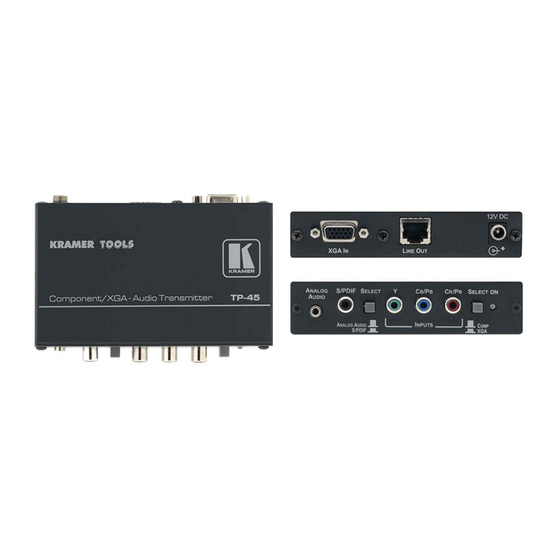
Your Component/XGA – Audio Transmitter and Receiver Figure 2 Table 2 define the underside of the TP-45: Figure 2: TP-45 Component/XGA – Audio Transmitter (Underside) Table 2: TP-45 Component/XGA – Audio Transmitter (Underside) Features Feature Function VS Switch Slide the switch up (to NEG.) to change the VS polarity to negative polarity;... -
Page 10: Your Tp-46 Component/Xga - Audio Receiver
Figure 4 Table 4 define the TP-46: Figure 4: TP-46 Component/XGA – Audio Receiver 1 Using a straight pin to pin UTP cable with RJ-45 connectors at both ends (the PINOUT is defined in Table 6 Figure KRAMER: SIMPLE CREATIVE TECHNOLOGY... -
Page 11: Figure 5: Tp-46 Component/Xga - Audio Receiver (Underside)
XGA OUT 15-pin HD (F) Connect to the XGA acceptor Connector LINE IN RJ-45 Connector Connect to the LINE OUT RJ-45 connector on the TP-45 LINE OUT RJ-45 Connector Connect to the LINE IN connector on an additional TP-46 12V DC +12V DC connector for powering the unit ANALOG AUDIO 3.5mm... -
Page 12: Connecting A Component/Xga - Audio Distribution System
The modes of the system are determined by setting the VIDEO SELECT and AUDIO SELECT switches on the TP-45 or TP-45RC. Whatever modes are set at the transmitter the video and audio signals are sent to the receiver and any additional cascaded receivers 1 There is no signal conversion;... -
Page 13: Connecting The System In Xga Mode
2 Or you can connect a digital audio source to the S/PDIF RCA connector 3 Not supplied. The complete list of Kramer cables is on our Web site at http://www.kramerelectronics.com 4 By default, both switches are set down (for normal V SYNC and H SYNC polarity) -
Page 14: Figure 6: Component/Xga - Audio Distribution System, Xga Mode
Figure 6: Component/XGA – Audio Distribution System, XGA Mode 1 If you cannot connect the power to both the TP-45 and TP-46, you can just connect the power to the TP-46 2 Use a screwdriver to carefully rotate the trimmer, adjusting the appropriate level... -
Page 15: Connecting The System In Component Video Mode
5 Alternatively, you can connect an analog audio acceptor, or you can connect both 6 If you cannot connect the power to both the TP-45 and TP-46, connect it to the TP-46 only. If more than one TP-46 is connected, connect the power to each TP-46 unit... - Page 16 3 If more than one TP-46 unit is connected, adjust the level and cable compensation in sequence from the first TP-46 unit (that is connected directly to the TP-45) to the next and so on 4 By default, both switches are set down (for normal V SYNC and H SYNC polarity)
-
Page 17: Figure 7: Component/Xga - Audio Distribution System, Component Video Mode
Connecting a Component/XGA – Audio Distribution System TP-46 Audio I N E Plasma Display I N E To the next TP-46 unit TP-46 Audio I N E Plasma Display I N E TP-45RC I N E Audio Player Figure 7: Component/XGA – Audio Distribution System, Component Video Mode... -
Page 18: Connecting The Tp-45Rc Remote Control
LEDs according to the active mode. Figure 8: The TP-45RC Remote Control Connection 1 Each LED is driven by a 5V source and a 392Ω series resistor KRAMER: SIMPLE CREATIVE TECHNOLOGY... -
Page 19: Wiring The Twisted Pair Line In / Line Out Rj-45 Connectors
Connecting a Component/XGA – Audio Distribution System Wiring the Twisted Pair LINE IN / LINE OUT RJ-45 Connectors Table 6 Figure 9 define the twisted pair pinout, using a straight pin-to-pin cable with RJ-45 connectors: Figure 9: Twisted Pair PINOUT Table 6: Twisted Pair PINOUT EIA /TIA 568A EIA /TIA 568B... -
Page 20: Technical Specifications
1 component 1Vpp/75Ω (YPbPr) on 3 RCA connectors TP-46 1 twisted pair line In on an RJ-45 connector (video/audio) OUTPUTS: TP-45/RC 1 twisted pair line Out on an RJ-45 connector (video/audio) TP-46 1 twisted pair line Extension on an RJ-45 connector (video/audio) 1 VGA/UXGA 1Vpp/75Ω... - Page 21 EXCLUSION OF DAMAGES The liability of Kramer for any effective products is limited to the repair or replacement of the product at our option. Kramer shall not be liable for: 1. Damage to other property caused by defects in this product, damages based upon inconvenience, loss of use of the product, loss of time, commercial loss;...
- Page 22 For the latest information on our products and a list of Kramer distributors, visit our Web site: www.kramerelectronics.com, where updates to this user manual may be found. We welcome your questions, comments and feedback. Safety Warning: Disconnect the unit from the power supply before opening/servicing.
Need help?
Do you have a question about the TOOLS TP-45 and is the answer not in the manual?
Questions and answers