
Related Manuals for Kramer TOOLS TP-42


Summary of Contents for Kramer TOOLS TP-42
-
Page 1: User Manual
Kramer Electronics, Ltd. USER MANUAL Models: TP-41, Component – S/PDIF Line Transmitter TP-42, Component – S/PDIF Line Receiver... -
Page 2: Table Of Contents
Table 1: TP-41 Component – S/PDIF Line Transmitter Topside Features Table 2: TP-41 Component – S/PDIF Line Transmitter Underside Features Table 3: TP-42 Component – S/PDIF Line Receiver Topside Features Table 4: TP-42 Component – S/PDIF Line Receiver Underside Features... -
Page 3: Power Connect Feature
ADDENDUM: Included with user manuals for machines with a CAT5 connector This addendum describes the Power Connect feature used with Kramer machines, and the choice between STP and UTP CAT5 cables. Power Connect Feature The Power Connect feature lets you power a transmitter / receiver system by connecting just one power adapter to either the transmitter or the receiver. -
Page 4: Introduction
GROUP 6: Accessories and Rack Adapters; GROUP 7: Scan Converters and Scalers; and GROUP 8: Cables and Connectors 2 A separate power supply is included with each product. As an option, you can purchase the Kramer VA-50P 6 Port Universal 12-Volt Power Supply, enabling you to supply power to up to 6 Kramer devices that require 12VDC 3 Download up-to-date Kramer user manuals from the Internet at this URL: http://www.kramerelectronics.com... - Page 5 / receiver system. The TP-42 receives the CAT5 signal, decodes it and simultaneously distributes it to the YUV output. The TP-41 Component – S/PDIF Line Transmitter includes: A YUV input on 3 RCA connectors A digital audio input (S/PDIF)
-
Page 6: Your Component - S/Pdif Line Transmitter And Line Receiver
Your Component – S/PDIF Line Transmitter and Line Receiver This section describes the: TP-41 Component – S/PDIF Line Transmitter, see section 4.1 TP-42 Component – S/PDIF Line Receiver, see section 4.2 4.1 Your TP-41 Component – S/PDIF Line Transmitter For a description of the TP-41: Topside, see section 4.1.1... -
Page 7: Your Tp-41 Component - S/Pdif Line Transmitter Underside
Your Component – S/PDIF Line Transmitter and Line Receiver 4.1.2 Your TP-41 Component – S/PDIF Line Transmitter Underside Figure 2 and Table 2 define the underside of the TP-41: Figure 2: TP-41 Component – S/PDIF Line Transmitter Underside Table 2: TP-41 Component – S/PDIF Line Transmitter Underside Features... -
Page 8: Your Tp-42 Component - S/Pdif Line Receiver
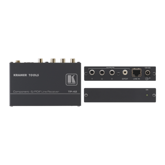
Underside, see section 4.2.2 4.2.1 Your TP-42 Component – S/PDIF Line Receiver Topside Figure 3 and Table 3 define the topside of the TP-42: Figure 3: TP-42 Component – S/PDIF Line Receiver Topside Table 3: TP-42 Component – S/PDIF Line Receiver Topside Features... -
Page 9: Your Tp-42 Component - S/Pdif Line Receiver Underside
Your Component – S/PDIF Line Transmitter and Line Receiver 4.2.2 Your TP-42 Component – S/PDIF Line Receiver Underside Figure 4 and Table 4 define the underside of the TP-42: Figure 4: TP-42 Component – S/PDIF Line Receiver Underside Table 4: TP-42 Component – S/PDIF Line Receiver Underside Features Feature Y EQ. -
Page 10: Connecting A Component - S/Pdif Distribution System
Figure 5: Component – S/PDIF Distribution System up to 300ft (100m) UTP Cable 1 On the TP-41, adjust the audio level and/or the Y, U, and V levels. On the TP-42, adjust the audio level, the audio EQ., the Y, U, and V levels, and/or the Y, U, and V EQ. -
Page 11: Wiring The Cat 5 Line In / Line Out Rj-45 Connectors
Green / White Blue Blue / White Green Brown / White Brown Pair 1 4 and 5 Pair 2 1 and 2 Pair 3 3 and 6 Pair 4 7 and 8 Figure 6: CAT 5 PINOUT KRAMER: SIMPLE CREATIVE TECHNOLOGY... -
Page 12: Technical Specifications
VIDEO: DC TP-41: 12VDC, 95mA TP-42: 12VDC, 82mA TP-41 / TP-42: 12 cm x 7.5 cm x 2.5 cm (4.7" x 2.95" 0.98", W, D, H) TP-41 / TP-42: 0.3 kg (0.67 lbs.) approx Power Supply AUDIO: 2.1Vpp (S/PDIF) AUDIO: 53.4MHz AUDIO: 78.4dB... - Page 13 EXCLUSION OF DAMAGES The liability of Kramer for any effective products is limited to the repair or replacement of the product at our option. Kramer shall not be liable for: Damage to other property caused by defects in this product, damages based upon inconvenience, loss of use of the product, loss of time, commercial loss;...
- Page 14 For the latest information on our products and a list of Kramer distributors, visit our Web site: www.kramerelectronics.com, where updates to this user manual may be found. We welcome your questions, comments and feedback. Safety Warning: Disconnect the unit from the power supply before opening/servicing.
Need help?
Do you have a question about the TOOLS TP-42 and is the answer not in the manual?
Questions and answers