
Subscribe to Our Youtube Channel
Related Manuals for Eneo ENC-1001L


Summary of Contents for Eneo ENC-1001L
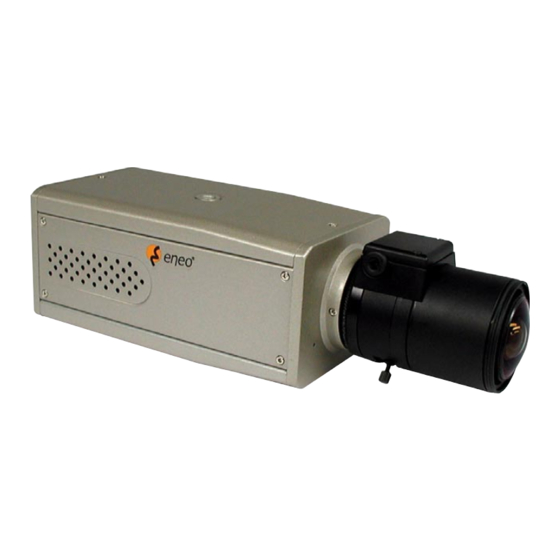
- Page 1 Installation and Operating Manual LAN Camera ENC-1001L with Quick Start Installation Guide ENC-WLAN Card for LANCAM ENC-1001L...
-
Page 2: Table Of Contents
APPENDIX 1. - SCAN IP ............................61 APPENDIX 2. - FAQ ..............................64 QUICK START INSTALLATION GUIDE (ENC-WLAN Card for LANCAM ENC-1001L) ..........65 APPENDIX 3. - PIN ASSIGNMENT OF THE 30 PIN MAIN CONNECTOR OF THE CAMERA PACKS VHM LAN01, VHM LAN02, VHM LAN03 AND VHM LAN04 ..................69... -
Page 3: Safety Precautions
SAFETY PRECAUTIONS • The instructions below must be followed for your own safety. • Please read the safety instructions and operating instructions before connecting the device and putting it into operation. • Keep the operating instructions safe for use at a later date. •... -
Page 4: Product Features
1. PRODUCT FEATURES 1.1 Product Introduction The LAN CAMERA is a state-of-the-art equipment of technological sophistication in its field. It combines multiple digital technical capabilities with the internal network functions of the network video camera. The user can imme- diately connect with a standard network, and the device can transmit the digital images to a remote browser. The LAN CAMERA is unlike the Web CAMERA, which connects the USB port or communication port with a personal computer. -
Page 5: Product Features
1.2 Product Features • An inbuilt Web Server and Network Interface. The LAN CAMERA is effective in assuring the safety of an independent digital camera. • Dual purpose: the LAN CAMERA can simultaneously export both the traditional analogs and the digital images. •... -
Page 6: Description Of The Front/Rear View
2. DESCRIPTION OF THE FRONT/REAR VIEW 2.1 Front Panel and Rear Panel Front Panel Rear Panel 1. MICROPHONE: The LAN CAMERA has an additional audio function. The device has a microphone built into its front panel which records sound. 2. RS-232 Port: The RS-232 communication port functions as a connector to an external control device. -
Page 7: Terminal Block
2.2 Terminal Block 1. ALM. OUT 2. GND 3. ALM. IN 4. ALM. RECOVER 1. ALARM OUT (OUTPUT): This is an alarm output trigger. Connect this to external devices such as buzzers or lights. 5V, 20mA 0V(Active) 2. GND: Ground contact 3. -
Page 8: Installation
6. POWER Indicator: Indicates the power status of the unit. The green light indicates the unit is activating. The red light indicates the power cannot move. If the CF Card is withdrawn in this mode, the card will break. 7. LAN Indicator: Indicates the LAN status of the unit. The green light indicates the 100Mbps Ethernet network is activating. -
Page 9: Connecting With A Nvr
3.3 CONNECTING WITH AN NVR Use a crossover LAN cable to connect directly to a NVR. CONNECT TO ETHERNET RJ-45 CONNECTOR CONNECT TO NVR ETHERNET PORT 3.4 UPDATING SYSTEM SOFTWARE If the system software of the LAN CAMERA needs to be upgraded, please take the following steps to safely update it. Important: Before carrying out the following procedures, please ensure the CF card is working and the file of system firmware is intact 1. -
Page 10: Lan Camera Cf Card Troubleshooting
Warning: 1. Don’t use FAT32 or NTFS or other file formats in Step 1. 2. Step1 to Step3 have to be done on a PC. 3. Make sure the file of UPDATE.BIN is a correct one in Step 3, or LANCAM will not work normally after updated. -
Page 11: Adjustment Of Lenses
Warning: 1. Performing this troubleshooting process may need a monitor, a PC, a card reader and some cables. 2. If CF Card is removed while storing or accessing data, data would be lost. 3. If there is a cross sign beside the „CF” icon, it means the CF Card has inserted into LAN CAMERA but cannot perform writing function. - Page 12 Adjustment of flange To obtain a sharp definition, point the camera at an object which is at least 5 times the focus for variable minimum lens distance (MOD) of the lens. (If this is 1m, the object must be at least 5m focus lenses distant from the camera).
-
Page 13: Network Configuration
4. Network Configuration 4.1 Cable Connections Please follow the instructions below to connect your LAN CAMERA to a computer or a network and to choose a proper RJ-45 cable configuration for connections. Physical specification of RJ-45 cable for Ethernet Wire Type Cat. - Page 14 4.1.2 Connect to a LAN Hub (INTRANET) The RJ-45 PIN configuration for connecting with a LAN Hub is shown below. TO PC NETWORK CARD TO NETWORK HUB/Switch / Router 4.1.3 Connect to WAN (INTERNET) The RJ-45 PIN configuration for connecting to a WAN is the same as connecting to a LAN. STATIC IP CABLE/XDSL MODEM TO ISP RJ-45...
-
Page 15: Configure Your Lan Camera Network Settings
4.2 Configure Your LAN CAMERA Network Settings Upon network hardware connection, you need to activate the network function and configure the proper network settings of the LAN CAMERA. 4.2.1 Enable DHCP Function This function can only work if the LAN which the unit is connected to has a DHCP server. If the DHCP server is working, the LAN CAMERA will obtain an IP address automatically from the DHCP server. -
Page 16: Tcp/Ip Communication Software
4.3 TCP/IP Communication Software Follow the instructions below to install the TCP/IP communication program into your computer. Click the Start menu from your computer, and point to the Settings/Control panel. Click the Network icon twice to enter the same setting windows. -
Page 17: Tcp/Ip Installation
Click on the Configuration tag; check if the TCP/IP is included among the network components list. If the TCP/IP is included, please process step 5. If it is not included, please follow step 4 to install the TCP/IP. 4.4 TCP/IP Installation During the installation, you will be requested to insert the Windows CD-ROM. -
Page 18: Tcp/Ip Configuration Setting
4.5 TCP/IP Configuration setting Click Start –> Settings –> Control Panel –> Network Select TCP/IP, and then click Properties. Before processing the LAN CAMERA installation in a WAN, please make sure the Internet connection works properly. If not, please contact your ISP provider. If you are using a DHCP server, please select Obtain an IP address automatically. -
Page 19: Connection Testing
4.6 Connection Testing With the previous settings, follow the instructions below to ensure whether you have established the connection successfully. Click Start –> Programs –> MS-DOS Prompt Type in ping 192.168.1.168 then Enter. (See the sample screen below) ** This IP is the LAN CAMERA IP address that is assigned for the connected LAN CAMERA in step2. - Page 20 If you receive a response as in the sample screen below, the connection hasn’t been successfully established. Please re-check all the hardware and software installation by repeating steps 1 to 5. If you still can’t establish the connection after rechecking, please contact your dealer. If you receive a response as in the sample screen below, you have successfully made the connection.
-
Page 21: Operating Instructions For Image Software And Network
5. Operating Instructions for Image Software and Network Two choices of software are available for linking up with the LAN CAMERA: (1) the Microsoft Internet Explorer; and (2) the LAN CAMERA VIEWER, a network browser in a PC which provides the functions of monitoring remote zones or watching recorded data through the TCP/IP protocol. -
Page 22: Microsoft Internet Explorer
5.1 Microsoft Internet Explorer 5.1.1 Connecting the LAN CAMERA 1. Start up the Microsoft Internet Explorer, and then follow the steps below to connect the LAN CAMERA. 2. Click the URL block at the top of the window. 3. Enter the URL address of the LAN CAMERA into the URL block and press the „Enter” button to enter the home page. 4. - Page 23 Browsing images from the LAN CAMERA The images from the LAN CAMERA will be displayed on the home page while going online with the LAN CAMERA. There are some buttons provided at the bottom of the home page for further setting: •...
- Page 24 5.1.2 Change Image Setting Please follow the steps below to change the image setting through the network if and as necessary. 1. Click the image button on the home page to enter the image-setting page. 2. Adjust the image setting including „Camera Title”, „Resolution”, „Quality”, „Fluorescent”, „BLC”, „Brightness”, „Hue”, „Saturation”, „Sharpness”, and „Viewer Type”...
- Page 25 5.1.3 Change the Network Setting Please follow the steps below to change the network setting through the network if and as necessary. • Set the network options and IP address 1. Click the network button in the home page to enter the network-setting page. 2.
- Page 26 • Change the Network Setting - FTP Please follow the steps below to change the FTP setting via the network if and as necessary to upload recording data live. 1. Click the FTP button at top left to enter the „FTP SERVER SETTING” page. 2.
- Page 27 • Change the Network Setting - SMTP Please follow the steps below to change the SMTP setting through the network if and as necessary. 1. Click the SMTP button at upper left above to enter the „SMTP SERVER SETTING” page (OPEN RELAIS SERVER). 2.
- Page 28 • Change the Network Setting - SNTP Please follow the steps below to change the SNTP setting through the network if and as necessary. 1. Click the SNTP button at upper left above to enter the „SNTP SERVER SETTING” page. 2.
- Page 29 • Change the Network Setting - DDNS The „Network” page has, on its upper left, the „DDNS” icon. Please follow the steps below to change the DDNS setting through the network if and as necessary. 1. Click the DDNS button at upper left above to enter the „DDNS SETTING” page. 2.
- Page 30 • Change the Network Setting - PPPoE The „Network” page has, on its upper left, the „PPPoE” icon. Please follow the steps below to change the PPPoE setting through the network if necessary. 1. Click the PPPoE button at upper left above to enter the „PPPoE SETTING” page. 2.
- Page 31 5.1.4 Change the System Setting Please follow the steps below to change the date and time of the system setting through the network if and as necessary. • Set the Date and Time of the system 1. Click the system button in the home page to enter the „System - Date and Time” page (default). 2.
- Page 32 • Change the System Setting - Users Please follow the steps below to change/add the users’ authority through the network if necessary. 1. Click the Users button on the left side of the „System - Date and Time” page to enter the „SYSTEM - USERS” page. 2.
- Page 33 • Change the System Setting - Digital I/O Please follow the steps below to change the Digital I/O through the network if necessary. 1. Click the Digital I/O button on the left side of the „System - Date and Time” page to enter the „SYSTEM - DIGITAL I/O SETTING”...
- Page 34 • Change the System Setting - Audio mechanism Please follow the steps below to change the Audio Mechanism through the network if necessary. 1. Click the Audio mechanism button on the left side of the „System - Date and Time” page to enter the „SYSTEM -AUDIO MECHANISM SETTING”...
- Page 35 • View the Event Logs. Please follow the steps below to view events through the network if and as necessary. 1. Click the button on the upper left above to enter the „EVENT LOG” page. 2. Choose one of the three buttons shown on the page to view an event when necessary. The three buttons are titled „First Page”, „Previous 20”, and „Next 20”.
- Page 36 5.1.5 Change the Application Setting Please follow the steps below to change the application setting through the network if and as necessary. • Change the Application Setting - FTP APPLICATION SETTING. Please follow the steps below to change the FTP setting via the network if and as necessary to upload recording data live.
- Page 37 • Change the Application Setting - CF CARD APPLICATION SETTING. Please follow the steps below to change the CF CARD setting via the network if and as necessary to upload recording data live. 1. Click the CF Card button on the top left to enter the „CF CARD APPLICATION SETTING” page. 2.
- Page 38 • Change the Application Setting -SMTP APPLICATION SETTING. Please follow the steps below to change the SMTP setting via the network if and as necessary. 1. Click the SMTP button on the left side to enter the „SMTP APPLICATION SETTING” page. 2.
- Page 39 2. Click „Enable RECORD - UPLOAD via FTP” to checkmark the attached box and activate the function. 3. Click „Enable RECORD - SAVE into CF Card” to checkmark the attached box and activate the function. 4. Click the Submit button to submit the new setting of the recording. 5.
- Page 40 • Change the Application Setting - ALARM APPLICATION ENABLE SETTING Please follow the steps below to change the setting via the network if and as necessary. 1. Click the Enable button on the left side of the record to enter the „ALARM APPLICATION ENABLE SETTING” page. 2.
- Page 41 • Change the Application Setting - ALARM - MOTION DETECTION Please follow the steps below to enable changes in the motion detection function of the alarm through the network if and as necessary. Set the motion detection: 1. Click the Motion detection button on the left side of the Alarm to enter the „ALARM - MOTION DETECTION” page. 2.
- Page 42 5.1.6 Change the CF Card Setting Please follow the steps below to change the CF Card setting through the network if and as necessary. • Change the CF Card Setting - FILELIST of MEMORY CARD Please follow the steps below to change the setting via the network if and as necessary. 1.
- Page 43 5.1.7 PPPoE & DDNS Using the PPPoE 1. Install the XDSL software (obtained from your ISP dealer) in your PC. 2. Search your LAN CAMERA’s IP address: you can use your Network Viewer’s Scan IP program, or just connect the LAN CAM and the Video monitor. The monitor screen will show the IP address on its right side. 3.
- Page 44 7. Click „Account” –> Type in your „Account password” again –> Click „Dynamic DNS (Add host)” –> Enter the „New dynamic DNS host page” –> Type in the „host name”, for example „abc123” –> Choose a host name from the drop - down list to the right of the „host name” entry (for example, „Homeip.net”) –> Click „Add host” –> The procedure is successfully completed –>...
-
Page 45: The Lan Camera Viewer
Follow the on-screen instructions to proceed with the rest of the installation procedure as they appear. 3. After the installation is complete, pop up the START menu from your computer, and point to Programs / ENEO LANCAM Network Viewer to open up the program selection page as shown below. - Page 46 5.2.3.1 Login the LAN CAMERA software Once Network View is executed a Login prompt will appear, you must enter the default User Name: admin, password: 9999 into the respective field. Click the „OK” button and enter the home page of the Network Viewer: both the user name and password must be filled correctly.
- Page 47 NOTE: Upon connection, the connection status box indicates the name and IP address of the selected device. If there’s a failure to connect, a „Fail” message appears on the screen right after the device IP address; otherwise an „OK” appears. To add more connections or units to the LAN CAMERA, please repeat the above instructions.
- Page 48 Viewing images View all the connected devices Once the connection has been established, click Login to enter the Multi-device mode window. (See the sample screen below) This window displays all the connected devices in the sequence which has been arranged when you established the connection.
- Page 49 Click to call the helper or assistant. Press to leave the Network Viewer program. The single sequence The multi sequence Click to page up. Click to page down. Click to enable the audio. Device title and image display area. Displays the title of each connected device and the time information of each displayed image in the top black bar.
- Page 50 Function Buttons Description Playback function bar • Play – Click to a recorded video from the PLAY LIST. • Pause – Click to freeze the image. • Stop – Click to stop playing back a recorded video or cease recording. •...
- Page 51 Change the PC SYSTEM SETUP Follow the instructions below to reconfigure the System Setup, Other Setup, Record Setup, and Alarm Setup:...
- Page 52 Set the record schedule to enter the Record Setup page. 1. When in the multiñdevice mode, and click (See the sample screen as in A above) 2. Click the Record Schedule to enter the Record Schedule page. 3. Set the Record Schedule to ON to enable the Record Schedule setting area. 4.
- Page 53 Change the Settings Via the Network Follow the instructions below to reconfigure the settings via the network.
- Page 54 Set the resolution and image quality of the image page 1. When in the multi-device mode, select a desired channel to enable this button, and click to enter the Lan Camera Setup page. (See the sample screen as in A above) 2.
- Page 55 Set the Settings of the Network page 3. When in the multi-device mode, select a desired channel to enable this button, and click to enter the Lan Camera Setup page. (See the sample screen as in A above) 4. Click the Network to enter the Network page. (See the sample screen as in B above) 3.
- Page 56 Set the Motion Detection of the Alarm Record page 1. When in the multi-device mode, select a desired channel to enable this button, and click to enter the Lan Camera Setup page. (See the sample screen as in A above) 2.
- Page 57 „Wrong File, Can’t Open”. Follow the instructions below to open an archived image from a CF card or a HDD. 1. Pop up the START menu from your computer, and point to Programs / ENEO LANCAM Network Viewer to open up the program selection page.
-
Page 58: Specifications
6. SPECIFICATIONS Type LAN CAMERA ENC-1001L EDP No. 91418 System CCIR/PAL Imager 1/3” interlaced CCD Sensitivity 0.76Lux at F1.2 (VT measurement result) at 50% video signal Resolution 480 TV lines (camera) 720x576, 352x288 Video Throughout Up to 30 (25) frames/sec at 352x240 (352x288),... -
Page 59: Function Of Client Pc
Accessories EDP No. Description 91422 16-Chanel Viewer Software for ENC-1000P 71852 CF Memory Card 128MB for ENC-1001/1002 71853 CF Memory Card 256MB for ENC-1001/1002 47147 F1.2/2.8mm DC Lens with No Focus Shift, 1/3” CS Mount 47148 F1.2/4mm DC Lens with No Focus Shift, 1/3” CS Mount 47149 F1.2/6mm DC Lens with No Focus Shift, 1/3”... -
Page 60: Dimensional Drawings
8. DIMENSIONAL DRAWINGS Dimensions: mm... -
Page 61: Appendix 1. - Scan Ip
APPENDIX 1. - SCAN IP Follow the instructions below to use the SCANIP software to search the LAN CAMERA devices from a local location. button to discover the connection of the all-type device in the LAN. The Device List will display the 1. - Page 62 Manual insertion of „Free IP Address” If you have clicked „No”, please manually type in insertions as required in the „Free IP Address”, „Gateway Address”, and „NET Mask”. Follow each insertion you make by typing in the „Login Name” and „Password”, and click „UPDATE”...
- Page 63 2. Select and double click any of the addresses in the „Free IP Address” box on the right to enter it into an IP Address on the left. 3. To change any IP address, type in the new address in the „Free IP Address” box on the right as well as the device „Login Name”...
-
Page 64: Appendix 2. - Faq
APPENDIX 2. - FAQ 1. How to disable the DHCP function and use a static IP instead? A: Turn the „DIP SWITCH” from „3” to „4” and vary the relative network settings, the IP Address, NetMask and Gateway on the image web page. 2. -
Page 65: Quick Start Installation Guide (Enc-Wlan Card For Lancam Enc-1001L)
Quick Start Installation Guide ENC-WLAN Card for LANCAM ENC-1001L Installation Accessories: Lan Camera Software (The Network Viewer). Before you can set up the wireless camera kit for your viewing pleasure over internet, you will need to install the wireless camera via either the Ad-hoc mode or the Infra-structure mode using the LAN set up guidelines. - Page 66 3. Click on the „START” menu from your computer, and point to „Programs / LanCam Network Viewer” to start the „Wireless Setup” program. Open the „wireless setup” and you will see the window shown below. 4. Click the „Synchronized” button to load the LANCAM’s settings. 5.
- Page 67 7. If you wish to change any of the above setting, type the new information directly into the window. The „Mode setting” has two options: „Infra-structure” and „Ad-hoc”. You should enter „Ad-hoc”, and click „Apply”. 8. Click the „Apply” button to transfer the new settings to the LANCAM. 9.
- Page 68 5. Power on every LANCAM: plug every LANCAM power cord into the outlet. Make sure the NVR is set at „power on” first before this step. 6. Register LANCAM to the NVR: a. Connect the NVR and one of the LANCAMs using the RS-232 cable. b.
-
Page 69: Vhm Lan01, Vhm Lan02, Vhm Lan03 And Vhm Lan04
Pin 6 brown/white Pin 7 brown Pin 8 eneo ® is a registered trademark of Videor Technical E. Hartig GmbH Exclusive distribution through specialised trade channels only. VIDEOR TECHNICAL E. Hartig GmbH Carl-Zeiss-Straße 8 · 63322 Rödermark/Germany Technical changes reserved.
Need help?
Do you have a question about the ENC-1001L and is the answer not in the manual?
Questions and answers