Williams Sound PERSONAL PA T35 Manual And User Manual
Wireless fm listening system fm wide-band / narrow-band transmitter
Hide thumbs
Also See for PERSONAL PA T35:
- Manual and user manual (32 pages) ,
- Manual and user manual (32 pages) ,
- Manual and user manual (36 pages)
Table of Contents
Advertisement
Quick Links
Download this manual
See also:
User Manual and Warranty
Advertisement
Table of Contents

Related Manuals for Williams Sound PERSONAL PA T35


Summary of Contents for Williams Sound PERSONAL PA T35
-
Page 1: Williams Sound
® Williams Sound Helping People Hear ANUAL AND UIDE PERSONAL PA T35 Transmitter ® Wireless FM Listening System Transmitter Model PPA T35 Optional Receiver Models PPA R30, R7, R7-4, R19, R19-6 MAN 110 C... -
Page 3: Table Of Contents
ENUS PPLICATION RESETS ANDWIDTH REQUENCY UDIO OURCE ILTER ILTER OMPRESSOR LOPE OMPRESSOR RF O UTPUT ECEIVER NSTRUCTIONS IDEBAND PTIONS REQUENCY HANGE NSTRUCTIONS ARROWBAND PTIONS ECEIVER ANAGEMENT ATTERY NFORMATION ROUBLE HOOTING UIDE ARRANTY YSTEM PECIFICATIONS ® Williams Sound Helping People Hear... -
Page 4: System Overview
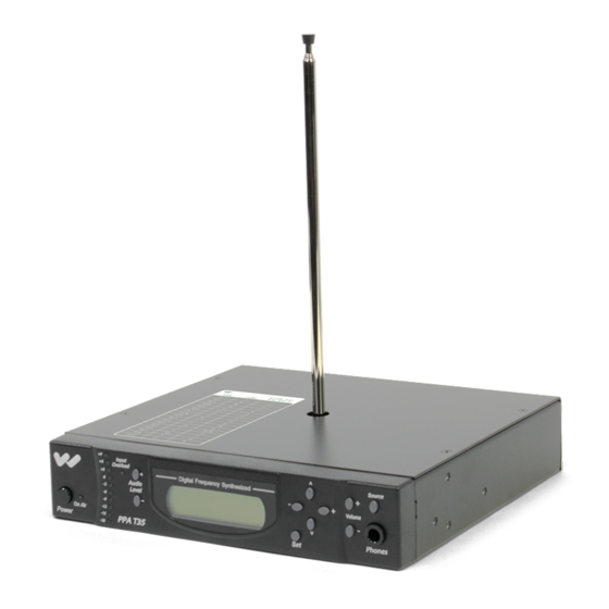
The PPA T35 is an FM Wide-band / Narrow-Band transmitter which operates in the 72-76 MHz frequency bandwidth. It is designed to be used with battery powered FM receivers: Compatible Williams Sound receivers include the R30, R7, R7-4 (Wide-Band), and the R19 and R19-6 (Narrow-band). Please contact Williams Sound Corp. for more information on available receivers: 800-843-3544. -
Page 5: Quick Setup Instructions
.5dB steps. See Figure 3. STEP 8: Listen with an FM receiver (see pages 19-23 for compatible Williams Sound receivers). Install the batteries, plug in the earphone, turn on the receiver and walk around the listening area. The sig- nal should be clear and quite loud when the volume is turned up. -
Page 6: Nstructions
The ANT 005 and ANT 024 cables are classified as Class II wiring and may be installed in conduit with other Class II wiring. The antenna SHOULD NOT be installed with Class I (power) wiring. DO NOT connect the coaxial cable to the building or electrical ground in any way. ® Williams Sound Helping People Hear... -
Page 7: Wiring And Connections
MIC, SIMPLEX-MIC and LINE. SEE PAGE 15 FOR AUDIO SOURCE CONTROLS. After the audio source selection has been made, plug in the appropriate audio source into the “Audio Input” jack in the rear of the T35. ® Williams Sound Helping People Hear... -
Page 8: Hearing Impaired
By constructing a simple resistive mixer, stereo (or 3 channel) sources can be connect- ed to the T35. Additional channels can be accommodated by adding a resistor for each source. Necessary resistors can be obtained from Williams Sound (Part Number RFC 472) or from any local electronics parts supplier. See Figure 6. -
Page 9: Avoiding Ground
ECORDING EVICE Use the Audio Line Out jack for monitoring, recording, or routing processed audio to another sound system. 8: A IGURE UDIO UTPUT PPA T35 Recording Device Audio Line Out Audio Line In ® Williams Sound Helping People Hear... -
Page 10: Features
.5dB steps. Holding down an Audio Level button continuously will automatically increase or decrease the audio input in .5dB increments until the button is released or the upper and lower limits are reached. Each action is immediately displayed on the LCD default display (Figure 9). ® Williams Sound Helping People Hear... - Page 11 The LCD display is used with the menu control buttons for configuring and setting up the T35. When the power of the unit is first turned on, the LCD screen displays a “Williams Sound” start- up screen. (NOTE: If the transmitter is not fully functional, the transmitter will stay on the start-up screen and the transmitter will not transmit.) After seven seconds, the “On Air”...
-
Page 12: Lcd Screen Menus
– -9 -9 On Air On Air Phones Phones Power Power PPA T35 PPA T35 Default Application Presets Bandwidth Frequency Audio Source High Pass Filter Low Pass Filter Compressor Slope Compressor Gain RF Output ® Williams Sound Helping People Hear... -
Page 13: Application Presets
If you are unsure of how these changes will impact the performance of the T35 transmitter, or how it will affect your hearing assistance application, please contact Williams Sound for assistance at 800-843-3544. ®... -
Page 14: Bandwidth
REMINDER: If the lock icon is displayed on the default display, the menu screens are locked, and you will not be able to make changes. To unlock the menu screens, refer to the instructions on page 11. ® Williams Sound Helping People Hear... -
Page 15: Audio Source
IMPORTANT: Listen to the transmitted audio through the headphone jack, especially when deciding on an appropriate high pass filter. This is a good way to ensure the listening audience is going to receive the highest audio quality. ® Williams Sound Helping People Hear... -
Page 16: Low Pass Filter
No additional action is necessary. NOTE: The installer of the T35 needs to take care in using compression, because some hearing impaired people cannot tolerate as loud of a sound as those with normal hearing. ® Williams Sound Helping People Hear... -
Page 17: C Ompressor G Ain
IMPORTANT: Listen to the transmitted audio through the headphone jack, especially when deciding on an appropriate compressor gain and slope. This is a good way to ensure the listening audience is going to receive the highest audio quality. ® Williams Sound Helping People Hear... -
Page 18: Rf Output
3) When the desired power level is displayed, press the “Set” button to save the change into memory. No additional action is necessary. After 30 seconds of inactivity, the LCD screen will return to the default display, where the selected power level will be displayed. ® Williams Sound Helping People Hear... - Page 19 A suitable adapter (Radio Shack Part #274-368) can be used so that stereo earphones operate on both sides. Williams Sound extensively evaluates the earphones and headphones included with the PPA R30. We can only assure optimum performance when Williams Sound earphones and headphones are used.
-
Page 20: Receiver
72.9, and 75.7 MHz*. It features a channel select knob, volume control on/off switch, and an earphone/charging jack. To operate, simply turn the select knob to the desired frequency, and adjust the volume control to a comfortable listening level. FIG. 15 On/Off Williams Sound Indicator Light Volume Control Earphone/ On/Off Switch... -
Page 21: Frequency
Ferrite Tuning R7- 4 "Slug" Most Williams Sound single channel Receivers are set at the factory to 72.9 MHz. The standard four-channel receivers (R7-4), channels 1-4, are usually set to frequencies 72.1, 72.5, 72.9, 75.7 MHz respectively. The Receiver must be tuned with a weak and somewhat noisy signal. If tuned too close to the transmitter, with a strong signal, the most accurate tuning of the receiver is not possible. - Page 22 NOTE: The R19 and R19-6 narrowband receivers use crystals to designate frequency selection and are therefore not field tunable. To select a different operating frequen- cy, the receiver must be returned to Williams Sound for service. FIG. 17 Narrow Band...
-
Page 23: Narrowband
The power LED indicator should illuminate. Turn the channel switch to the desired frequency,and adjust the volume control knob to a comfortable listening level. FIG. 18 Narrow Band Tone Controls Williams Sound Volume Control Earphone On/Off Switch Volume Jack... -
Page 24: Receiver Management
Nickel Metal Hydride or NiCad batteries, and only if the correct Williams Sound charg- er is used. Recharge batteries only with a Williams Sound CHG 200A 3V Dual Charger or the CHG 1600 Multiple Battery Charger. Make sure the receiver is turned off during charging. A complete recharge cycle takes about 14 hours. -
Page 25: Trouble -Shooting Guide
Check to see if the Audio Input level is set too high. If the “input overload” is illuminated, then the audio level needs to be adjusted. See page 10. Check for ground loops or noise on the input signal. See page 9 for more information. Call your Authorized Williams Sound dealer or representative. “ ”... - Page 26 This is likely an RF–induced disturbance in the other equipment. To remedy, try these steps in order until the buzz is eliminated: 1. Make certain the transmitter chassis is connected to the equipment cabinet rails. ® Williams Sound Helping People Hear...
-
Page 27: Warranty
If you experience difficulty with your system, call for Customer Assistance: 1-800-843-3544. If it is necessary to return the system for service, a Williams Sound representative will give you a Return Authorization Number (RA) and shipping instructions. Pack the system carefully and send it to: Williams Sound Corp. -
Page 28: System Specifications
YSTEM PECIFICATIONS Personal PA T35 Transmitter Dimensions, Weight: 8.45" (21.5 cm) W x 8.18" (20.8 cm) D x 1.72" (4.4 cm) H, 3.1 lbs. (1.4 kg) Color: Black with white legends Rack Mount: One EIA rack space high, 1/2 space wide 1–2 units can be mounted in a single rack space with optional RPK 005 (single) or... - Page 29 Earphone: Earbud-type with foam cushion, 3.5 mm plug, 32 Ω (Other styles available) Channel Selector: 4–position, rotary switch Warranty: Five Years, Parts and Labor. 90 days on cords, earphones, headphones, batteries and other accessories ® Williams Sound Helping People Hear...
- Page 30 Lo: 20 Hz / Mid: 120 Hz / Hi: 700 Hz Volume & On/Off: Combination, integral Channel Selector: PPA R19: 2-position, slide switch PPA R19-6: 6-position, rotary switch Warranty: Five Years, Parts and Labor. 90 days on cords, earphones, headphones, batteries and other accessories ® Williams Sound Helping People Hear...
- Page 32 ® Williams Sound Helping People Hear w w w . w i l l i a m s s o u n d . c o m MAN 110C ©2003 Williams Sound Corp.
Need help?
Do you have a question about the PERSONAL PA T35 and is the answer not in the manual?
Questions and answers