Williams Sound PPA T35 Manual And User Manual
Wireless fm listening system
Hide thumbs
Also See for PPA T35:
- Specification (4 pages) ,
- Manual and user manual (36 pages) ,
- Manual and user manual (32 pages)

Related Manuals for Williams Sound PPA T35


Summary of Contents for Williams Sound PPA T35
- Page 1 ANUAL AND UIDE ® PERSONAL PA T35 Transmitter Wireless FM Listening System Transmitter Model PPA T35 Optional Receiver Models PPA R37, PPA R35-8 MAN 110Q...
-
Page 3: Table Of Contents
PERSONAL PA ™ T35 T RANSMITTER ANUAL AND UIDE ONTENTS ..............4 YSTEM VERVIEW . -
Page 4: System Overview
800-843-3544. Or, visit us on the web: www.williamssound.com. Developed for hearing assistance in places of public access, the PPA T35 is designed for those who need help overcoming background noise, reverberation, or distance from the sound source. It includes a complete audio processor optimized for the needs of hearing impaired persons and is easily integrated with your existing sound system. -
Page 5: Quick Setup Instructions
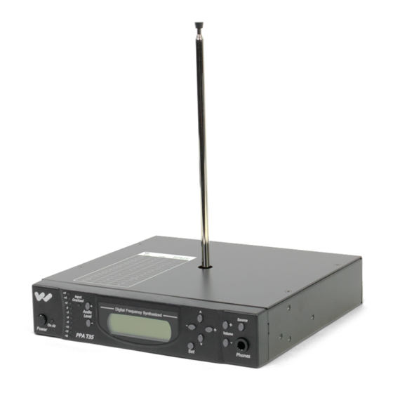
UICK ETUP NSTRUCTIONS Position the PPA T35 transmitter near the sound system or mixer from which it will receive audio. STEP 1: Install the ANT 025 whip antenna. Gently thread the ANT 025 onto the stud recessed in the hole on the top of the transmitter. The antenna length must NOT exceed 28 inches when fully extended. -
Page 6: Instructions
For rack mounting, consider installing a remote antenna (see following section). The PPA T35 is shipped standard with a single ANT 025 whip antenna. The ANT 025 threads on to a stud recessed in a hole on the top of the transmitter. Screw the antenna clockwise until the connec- tion is secure (Figure 4). -
Page 7: Wiring And Connections
IRING AND ONNECTIONS FIG. 5: R IEW OF Connect the TFP 016 power supply to the “Power In” jack located U.S. A OWER UPPLY ONNECTION FOR PPLICATION on the rear of the T35 transmitter. TFP 016 NOTE: The power on the T35 will not be activated until the power button Power on the front of the T35 is pressed into the “on”... -
Page 8: Hearing Impaired
ISTENERS ommend following these general guidelines: The PPA T35 transmits audio with excellent fidelity. Therefore, the audio source signal should be of the highest audio quality and not subject to a compressor, limiter, reverberation, or other signal processing equipment. The T35 has an effective audio processor. If compression is desired in the audio, refer to page 16-17 for features and controls. -
Page 9: Avoiding
A hum created by a ground loop can often be eliminated by connecting a capacitor in series with the audio VOIDING UM IN THE UDIO AS A ESULT OF A ROUND line shield to the transmitter’s ground. This method also maintains good RF shielding. Determining the effectiveness of this method for your installation usually requires some experimentation. -
Page 10: Features
& F ONTROLS EATURES . 9: PPA T35 F RONT Push-button switch turns the transmitter on or off. The wall mounted power supply stays on at all times. OWER UTTON Indicates when power is on and radio frequency is transmitting. - Page 11 LCD M ISPLAY When the power of the unit is first turned on, the LCD screen displays a “Williams Sound” start-up screen. (NOTE: If the transmitter is not fully functional, the transmitter will stay on the start-up screen and the transmitter will not transmit.) After seven seconds, the “On Air” LED will illuminate and the default screen will be displayed (Figure 10).
-
Page 12: Lcd Screen Menus
The first screen (M0) gives important overall system settings. The following nine menu screens (M1-M9) are LCD S CREEN ENUS UICK EFERENCE used to configure and setup the T35. To make a screen selection, navigate to the desired LCD menu by press- ing the “... -
Page 13: Application Presets
If you are unsure of how these changes will impact the performance of the T35 transmitter, or how it will affect your hearing assistance application, please contact Williams Sound for assistance at 800-843-3544. -
Page 14: Bandwidth
The default LCD menu screen (as shown on page 11, Figure 10) will always display the user selected (M2) ANDWIDTH bandwidth as “Wideband” or “Narrowband.” The T35 is shipped from the factory in Wideband mode. First determine the bandwidth of the associated receiver, then set the T35 to that bandwidth: 1) Press the “... -
Page 15: Audio Source
The Audio Source control menu is used to configure the T35 for a proper audio source connection. The (M4) UDIO OURCE transmitter will accept the following audio sources: 1) Balanced Microphone on a 3-pin (XLR) connector without simplex power. 2) Balanced Microphone with 12 volt simplex power (DIN 45596) on a 3-pin (XLR) connector. 3) Balanced/Unbalanced microphone without power on 1/4 inch jack 4) Balanced/Unbalanced Line on a 3-pin (XLR) connector. -
Page 16: Low Pass Filter
The low pass filter will help to remove high frequency “noise” from the transmitted audio signal. This is typ- (M6) ILTER ically used when there is a hiss in the audio line as a result of room noise, speech sibilants, or other high fre- quency unpleasantries. -
Page 17: Compressor Gain
The T35 has two selectable modes of compressor gain: Normal and Reduced. For applications such as (M8) OMPRESSOR music and voice, where high audio quality is desirable, Reduced is the recommended mode of operation. Reduced compression gain minimizes the amount of low input level boost and alteration in the sound which compression can cause. -
Page 18: Rf Output
The T35 has three selectable transmitter power levels: FULL, MEDIUM, LOW POWER, or OFF AIR. RF O (M9) UTPUT By default the T35 is set to “Full” power mode. For general listening applications, FULL power is the preferred mode of operation. “Full power” provides the T35 with an operating range of up to 1000 ft. For special listening applications, it may be desirable to reduce the overall operating range on the T35 if: 1) The audio transmission is to be contained to a “smaller”... -
Page 19: Safety Information
If you have a pacemaker or other medical device, make sure that you are using this product in accordance with safety guidelines established by your physician or the pacemaker manufacturer. ECYCLING NSTRUCTIONS Help Williams Sound protect the environment! Please take the time to dispose of your ATTERY AFETY AND ISPOSAL equipment properly. - Page 20 1. Insert two (2) AA batteries ensuring correct polarity. If rechargeable NiMH batteries are to be used PERATING THE RECEIVER with the receiver and a Williams Sound charger, make sure the Alkaline/NiMH switch inside the battery compartment is set to NiMH before charging. See FIG A.
- Page 21 ONNECTING ARPHONES ate properly. If stereo headphones are used, sound will be heard only in one side. Williams Sound evaluates each earphone and headphone used with the PPA R35-8 receiver; we can only assure optimum performance when Williams Sound earphones and headphones are used.
- Page 22 PPA R37 PPA R35-8 NSTALLATION FOR Position the belt clip on the rear of the PPA R37 and PPA R35-8 receivers as shown in Figure 16a. Turn the NSTALL belt clip 180º left or right as shown in Figure 16b. The belt clip is now installed and ready for use. Turn the belt clip 180º...
-
Page 23: Receiver Management
IMPORTANT: Batteries installed in the receiver may only be charged if they are NiMH or Ni-Cad Batteries, and only if a Williams Sound charger is used. Make sure the receiver is turned off during charging! Use the chart below to select a charger for your Williams Sound 72-76 MHz receiver. -
Page 24: Trouble -Shooting Guide
Check for ground loops or noise on the input signal. See page 9 for more information. Call your Authorized Williams Sound dealer or representative. The Audio Level Control may be set too high. You’re probably also seeing the +6 level indicator “... - Page 25 Make sure the FM receiver is ON. Make sure the batteries are properly installed (observing proper polarity). If the batteries are rechargeable, it may be necessary to charge the batteries overnight. Make sure the FM receiver is operating on the same frequency as the T35. Make sure the receiver is operating on the same bandwidth as the T35: Wideband or Narrowband.
- Page 26 6. Make sensitive equipment more immune to RFI/EMI. The manufacturers of your audio equipment may offer application notes for this purpose. Williams Sound offers a document giving suggestions for improving RF immunity in existing audio equipment (Technical Bulletin: Buzz Or Hum In The...
-
Page 27: Warranty
IMITED ARRANTY Williams Sound products are engineered, designed, and manufactured under carefully controlled conditions to provide you with many years of reliable service. Williams Sound warrants the Personal PA Transmitter ™ against defects in materials and workmanship for FIVE (5) years. During the first five years from the pur- chase date, we will promptly repair or replace the Personal PA Transmitter. -
Page 28: System
YSTEM PECIFICATIONS Personal PA T35 Transmitter Dimensions, Weight: 8.45" (21.5 cm) W x 8.18" (20.8 cm) D x 1.72" (4.4 cm) H, 3.1 lbs. (1.4 kg) Color: Black with white legends Rack Mount: One EIA rack space high, 1/2 space wide 1–2 units can be mounted in a single rack space with optional RPK 005 (single) or RPK 006 (double) Rack Mount Kits Power:... - Page 29 Dimensions: 4.1” H x 2.85 W x 1.38” D (104 mm x 72 mm x 35 mm) PPA Select™ Receiver (Model PPA R37) Weight: 4.6 oz (130 g) with batteries, 2.6 oz w/o batteries (73g) Color: Black Battery Type: Two (2) AA non-rechargeable alkaline batteries (BAT 001), approx. 48 hours battery life; or Two (2) AA rechargeable NiMH batteries (BAT 026), 1500 mAh, approx.
- Page 32 MAN 110Q ©2011 Williams Sound, LLC...
Need help?
Do you have a question about the PPA T35 and is the answer not in the manual?
Questions and answers