Table of Contents
Advertisement
Quick Links
Becker Flugfunkwerk GmbH · Baden Airpark · 77836 Rheinmünster · Germany
Telephone +49 (0) 7229 / 305-0 · Fax +49 (0) 7229 / 305-217
http://www.becker-avionics.com · e-mail: info@becker-avionics.de
Audio Control Unit
ACU6100-x-(xxx)
Installation and Operation
Manual
DV 64440.03
Issue 1
September 2005
Change 2
October 2008
Advertisement
Chapters
Table of Contents

Related Manuals for Becker ACU6100 series


Summary of Contents for Becker ACU6100 series
-
Page 1: Installation And Operation
Installation and Operation Manual DV 64440.03 Issue 1 September 2005 Change 2 October 2008 Becker Flugfunkwerk GmbH · Baden Airpark · 77836 Rheinmünster · Germany Telephone +49 (0) 7229 / 305-0 · Fax +49 (0) 7229 / 305-217 http://www.becker-avionics.com · e-mail: info@becker-avionics.de... - Page 2 2-I - 2-II 09/2005 2-1 - 2-10 09/2005 3-I - 3-II 09/2005 09/2005 10/2008 3-3 - 3-12 09/2005 3-13 10/2008 3-14 - 18 09/2005 DV 64440.03 / Article Number 0589.845-071 © 2005 by Becker Flugfunkwerk GmbH / All rights reserved...
- Page 3 ISO 9001 Certified Quality System Das Becker- Qualitätsmanagementsystem ist zertifiziert nach: The Becker quality management system is certified according to: DIN EN ISO 9001 CERT Reg. - Nr. 12 100 20988 Zulassungen und Genehmigungen: Licenses and Approvals: BWB-1921Y-B07/04/01 Zulassung als Luftfahrtbetrieb für Luftfahrtgerät der Bundeswehr Manufactures license for aviation equipment to the German armed forces DE.21G.0075...
-
Page 5: Table Of Contents
ACU6100 TAB LE OF CON TENTS Sec ti on GE NE RAL IN FOR MA TI ON Page In tro duc ti on Application Ge ne ral des crip ti on 1.3.1 Me cha ni cal des crip ti on 1.3.2 Elec tri cal des crip ti on 1.3.2.1... - Page 6 ACU6100 BLANK Page 1-II DV 64440.03/.04 Is sue 1 Sept./ 2005...
-
Page 7: In Tro Duc Ti On
In tro duc ti on The BECKER ACU6100-X-(XXX) Au dio Con trol Unit is des cri bed in the ”In stal la ti on and Ope ra ti on” DV 64440.03 and “Mai nten an ce and Re pair” DV 64440.04 ma nu als. -
Page 8: Ge Ne Ral Des Crip Ti On
ACU6100 Ge ne ral des crip ti on 1.3.1 Mechanical description The Audio Con trol Unit is de sig ned for in stal la ti on in the ope ra tor con so le of air craft. The di men sions cor re spond to the ARINC 601 stan dard for con trol units. - Page 9 ACU6100 P-BIT, I-BIT, C-BIT functio na li ty with op ti cal in di ca ti on of test sta tus/re sult Fall-back to Back-Up ope ra ti on upon fai lu re of po wer supp ly (ba ckup po wer supp ly from air craft ne ces sa ry!);...
- Page 10 ACU6100 Vo lu me board (bot tom) The fol lo wing are moun ted on the vo lu me board (bot tom) 8 mo ni to ring but tons to switch on /off re cei ver mo no tring and in du vi du al vo lu me con trol. Il lu mi na ti on board The fol lo wing are moun ted on the íl lu mi na ti on board VOICE but ton with LED to switch on and off the ident fil ter (green LED: fil ter on, ident...
-
Page 11: Identification Of Article
ACU6100 Identification of article 1.4.1 Types of Audio Control Unit Audio Control Unit Part- number ACU6100-X-(XXX) ACU6100-X-(XXX) Illumination Dimming = 0 ..28 V (green) Dimming = 0 ..5 V (green) Dimming = 0 ..28 V (white) Dimming = 0 ..5 V (white) Panel configurations Standard Panel Inlays Blank Panel Inlays... -
Page 12: Tech Ni Cal Data
ACU6100 Tech ni cal da ta 1.5.1 Po wer supp ly Supp ly vol ta ge (Bus) I 27.5 V DC no mi nal 18.0 V DC emer gen cy Supp ly vol ta ge (Bus) II 27.5 V DC nominal 18.0 V DC emergency Back-Up vol ta ge (Bus) II 27.5 V DC no mi nal... -
Page 13: Unit Con Nec Tors
ACU6100 1.5.4 Unit con nec tors Unit con nec tor P1 10-pol. series 851 Con trol bus- con nec tor P2 19-pol. series 851 - loc king de vi ce bayo net 1.5.5 En vi ron men tal con di tions In put vol ta ge ran ge 22.0 to 30.3 V DC - no mi nal in put vol ta ge... -
Page 14: Approvals
ACU6100 Appro vals LBA-No.: ETSO ETSO - C50c Au dio Se lec tor Pa nels and Am pli fiers Soft wa re EU RO CAE/RTCA DO-178B/ ED-12B Le vel C En vi ron men tal qua li fi ca ti on (EU RO CAE/RTCA ED-14D/DO-160D) Cha rac te ris tic Section Category... -
Page 15: Sco Pe Of De Li Very
ACU6100 Cha rac te ris tic Section Category Condition ED-14D/DO-160D Ra dio fre quen cy sus cep ti bi li ty 20.0 Emis si on of RF 21.0 Light ning in du ced tran sient sus cep ti bi li ty 22.0 A3E3 Light ning di rect effects... - Page 16 ACU6100 Blank Page 1-10 DV 64440.03/.04 Issue 1 Sept./2005...
- Page 17 ACU6100 TAB LE OF CON TENTS Sec ti on IN STAL LA TI ON Page Ge ne ral In spec ti on be fo re in stal la ti on Me cha ni cal in stal la ti on Air craft wi ring 2.4.1 Ge ne ral 2.4.2...
- Page 18 ACU6100 BLANK Page 2-II DV 64440.03/.04 Is sue 1 Sept./2005...
-
Page 19: General
ACU6100 Sec ti on IN STAL LA TI ON General The in stal la ti on of the Au dio Con trol Unit de pends on the type of air craft and its equip ment and the re fo - re only ge ne ral in for ma ti on can be gi ven in this sec ti on. - Page 20 ACU6100 Fig. 2-1 In stal la ti on di men sions Au dio Con trol Unit (mea su res in mm) Page 2-2 DV 64440.03/.04 Issue 1 Sept./2005...
- Page 21 ACU6100 19 pol. 10 pol. B-BUS Fig. 2-2 Phy si cal lo ca tions of Au dio Con trol Unit con nec tors Dev.Nr. hardwired Reset in safety related Dim, IC hotmike CAN1 CAN2 Power B-BuS Reset out Fig. 2-3 Lo gi cal pin as signment Au dio Con trol Unit DV 64440.03/.04 Issue 1 Sept./2005 Page 2-3...
-
Page 22: Panel Illumination
ACU6100 2.4.2 Panel illumination The Au dio Con trol Unit is fit ted with pa nel lighting. It can also be con nec ted via a dim mer sys tem. Pa nel illumination con nec ti on Re mark Plug P 1 - Pin E Dim Con trol in 1 (pa nel il lu mi na ti on) Plug P 1 - Pin A Dim Con trol in 2 (bright ness of LEDs) - Page 23 ACU6100 Con nec ti on Re mark BB1-HI-out BB1-Lo-out BB1-SH-out BB2-HI-in BB2-Hi-out BB2-SH-in BB2-HI-out BB2-LO-out BB2-SH-out ACU6100 all P1 DC 1 +27,5V C DC 1 GND D DC 2 +27,5V G DC 2 GND F PTT H Back Up Switch Out B Slave Switch Out K IC Hot Mike In J Dim Control 1 In E...
-
Page 24: Con Fi Gu Ra Ti On Soft Wa Re
ACU 6100-X-(XXX) ACU6100 all P2 Device Address Bit0 L Device Address Bit1 M Device Address Bit2 A Device Address Bit3 B Address Ground N Reset out U Reset in V CAN1 in (HI) C CAN1 in (LO) D CAN1 in (shield) P CAN1 out (HI) E CAN1 out (LO) F CAN1 out (shield) R... - Page 25 ACU6100 Fig. 2-6 Bus in ter wi ring with 3 ACUs DV 64440.03/.04 Issue 1 Sept./2005 Page 2-7...
- Page 26 ACU6100 Note 120 Ω. The ends of each bus must be ter mi na ted with It can be in the har ness or on a se pa - ra te juncti on block. For cor rect ope ra ti on with one ACU re mo ved, a dum my ma ting con nec tor will have to be con nec ted in it’s pla ce.
- Page 27 Co-Pilot ACU 1 Cabin ACU 5 Cabin ACU 3 B Bit 3 B Bit 3 B Bit 3 A Bit 2 A Bit 2 A Bit 2 M Bit 1 M Bit 1 M Bit 1 L Bit 0 L Bit 0 L Bit 0 N Addr.
- Page 29 ACU6100 TABLE OF CONTENTS Section OPERATION Page Operating controls Description and function of the operating controls and indicators Operating instructions 3.3.1 Preparations (power-up test) Transceiver operation 3.4.1 Transceiver monitoring 3.4.2 Individual transceiver channel volume adjustment 3.4.3 Monotoring TX- channel volume adjustment 3.4.4 Main volume adjustment Selection of transmission mode...
- Page 30 ACU6100 Built IN Test 3-16 3.9.1 Power- up built in test (P-Bit) 3-16 3.9.2 Continuous built in test (C-Bit) 3-16 3.9.3 Initiated built in test (I-Bit) 3-16 3.10 Emergency operation 3-17 3.10.1 Slave operation 3-17 3.10.2 Back-up operation 3-17 3.10.3 Back-up switch activated 3-17 3.10.4...
-
Page 31: Operation
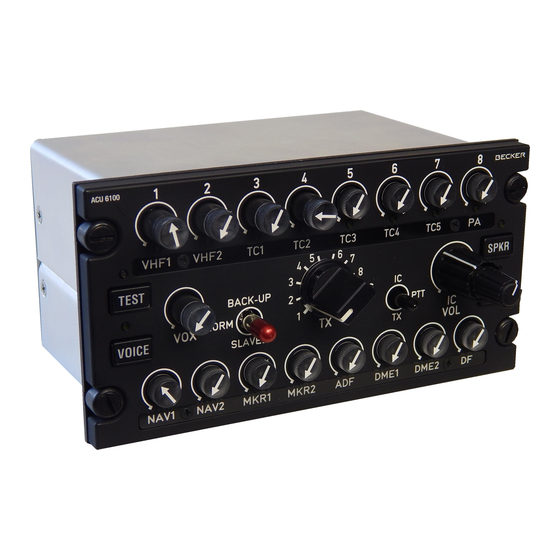
ACU6100 Section OPERATION Operating controls Fig. 3-1 Front panel of the Audio Control Unit with generic button-inscription Description and function of the operating controls and indicators Item Control / Indicator Description Function On/Off switch for every TX channels and TX1 to TX8 controls 8 potentiometer with individual volume adjust for audio monitoring push-push switches... - Page 32 ACU6100 Item Control / Indicator Description Function IC volume control Potentiometer Volume adjustment for intercom “SPKR” indicator LED (green) LED on = Speaker is on LED off = Speaker is off Push-button On/Off switch for audio monitoring via the “SPKR” button speaker “ISOL/ CALL”...
-
Page 33: Operating Instructions
ACU6100 Operating instructions 3.3.1 Preparations (power-up test) 1. Switch on the unit by using the audio selector master switch (circuit breaker). 2. When the Audio Control Unit is powered, the devicesis starts an internal self test procedure. All the microprocessors and memories are tested as well as data transfer between Audio Control Units and remote electronic unit. -
Page 34: Transceiver Operation
ACU6100 Transceiver operation 3.4.1 Transceiver monitoring For transceiver monitoring, a TX-channel is activated by push release of the respective knob. Knob released monitoring ON Knob impressed monitoring OFF Several transceivers may be selected for monitoring at the same time. 3.4.2 Individual transceiver channel volume adjustment The individual volume for the monitored channels can be selected by turning the respective knob. -
Page 35: Selection Of Transmission Mode
ACU6100 Selection of transmission mode 3.5.1 Selecting a radio for transmission For transmission with an individual radio, the transceiver is pre-selected by means of the TX-selector rotary switch in the centre of the Audio Control Unit. In the given example TX-channel 1 is pre-selected for transmission. -
Page 36: Transmission Mode
ACU6100 3.5.5 Transmission mode By pressing a PTT switch (on panel or external), the following actions will result: The selected transmitter will be keyed. The green LED below the associated channel volume knob is flashing. Note: During transmission, all received signals possibly selected, are muted as well as signals originating from aircraft intercommunication. -
Page 37: Dual Transmission Mode
ACU6100 By speaking into the microphone while in transmission mode, the following actions will results: The activated transmitter is modulated A sidetone is audible with a volume that is in accordance with the preselection in the in- stallation setup. The individual volume for the monitored channels can be selected by turning the respective knob. -
Page 38: Receiver Operation
ACU6100 Receiver operation 3.6.1 Receiver monitoring For receiver monitoring, a RX-channel is activated by push release of the respective knob: Knob released ® monitoring ON Knob impressed ® monitoring OFF Several receivers may be selected for monitoring at the same time. In the given example, RX-channel 1, 2 and 6 are selected for monitoring. -
Page 39: Main Volume Adjustment
ACU6100 3.6.3.1 Main volume adjustment Main volume can be adjusted at any time by turning the VOL control. This action adjusts the sum volu- me of all activated TX- and RX-channels. 3.6.4 Voice filter activation The system has the possibility to activate a 1020Hz notch filter for all the RX-channels. This is to sur- press identification codes in the incoming audio signals from navigation receivers (e.g. - Page 40 ACU6100 Pressing the key once again, the speaker is switched off and the LED goes off. When speaker mode is active with an individual Audio Control Unit, voice controlled intercommunicati- on (VOX) is disabled. Intercom is still possible by activating the external IC button or by pressing the PTT button while the TX-selector rotary switch is in position ”IC”.
-
Page 41: Intercommunication
ACU6100 In ter com mu ni ca ti on 3.7.1 Vir tu al In ter com Cir cuits The re are two in ter com cir cuits pro vi ded by the DVCS6100 Sys tem: Cock pit crew Ca bin crew The in ter com in si de one of the se 2 cir cuits can not be in ter rup ted. -
Page 42: Cockpit Call/Isol Functionality
ACU6100 3.7.2 Cockpit “ISOL/CALL” Functionality In the cockpit, the ”ISOL/CALL” button is used to toggle the connection/disconnection between the cockpit and the cabin intercom circuits. A LED above this button indicates the actual status of the connection: LED on ® cockpit and cabin intercom circuits are isolated LED off ®... -
Page 43: Voice Controlled Intercom
ACU6100 3.8.1 Voice Controlled Intercom In positions ”1” to ”8” and ”D” of the TX selector rotary switch, Voice Controlled Intercom (VOX) is estab- lished without the need for any further action (assuming no transmitter is keyed). Voice Controlled Intercom can be activated or deactivated by switching functionality of the VOX knob. VOX knob released Voice Controlled Intercom ON VOX knob impressed Voice Controlled Intercom OFF... -
Page 44: Ic Volume Adjustment
ACU6100 3.8.5 IC volume adjustment For individual intercom volume adjustment, the ACU provides a dedicated potentiometer on the front panel. The intercom volume is independent from the main volume. The transmission mode always has a higher priority than the intercom- munication mode. If an operator activates the transmission mode for any transceiver, the ACU stops its ”VOX”... -
Page 45: Winchman Volume Level Functionality
ACU6100 3.8.6.2 Winchman volume level functionality If the winchman volume push button is pressed a short time (0.3s to £ 2s), the volume level is increased by one step, until the maximum value is reached. If the winchman volume push button is pressed for a time ³... - Page 46 ACU6100 Built in test 3.9.1 Power-up built in test (P-BIT) Every time the system is powered, an internal self test procedure is started. While the test is running, the LED above the ”TEST” push button illuminates. The test lasts up to 4 se- conds.
- Page 47 ACU6100 3.10 Emergency operation 3.10.1 Slave operation Copilot ACU Pilot ACU When switching the emergency toggle switch to position ”SLAVED” on ACU 1 or ACU 2, the matching headset is disconnected from it’s audio processing circuits in the Remote Electronic Unit and it’s mike and phone capsules are directly paralleled to the headset of the remaining ACU.
- Page 48 ACU6100 Intercom volume level is fixed to 50% No actions on the ACUs are supported 3.10.4 Automatic activation When the two main power supply busses fail or if a fatal defect occurs within the unit’s internal supply, the security logic falls back to Back-Up operation even if the ”BACK-UP” switch had not been activated. The signal routings and functionalities are as described in chapter 3.10.3 Page 3-18 DV 64440.03/.04 Issue 1 Sept./2005...
Need help?
Do you have a question about the ACU6100 series and is the answer not in the manual?
Questions and answers