Sign In
Upload
Manuals
Brands
Becker Manuals
Control Unit
ACU6100 series
Becker ACU6100 series Manuals
Manuals and User Guides for Becker ACU6100 series. We have
2
Becker ACU6100 series manuals available for free PDF download: Installation And Operation Manual
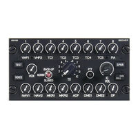
Becker ACU6100 series Installation And Operation Manual (64 pages)
Brand:
Becker
| Category:
Recording Equipment
| Size: 4.17 MB
Table of Contents
Table of Contents
5
List of Abbreviations
8
1 General Description
11
Introduction
12
Purpose of Equipment
12
1.3 Variants Overview
13
Acu6100-X-(XXX)
13
Figure 1: ACU6100-X-(X9X) - RX Variant
13
Acu6100-X-(XXXX)
14
Software Status
14
Figure 2: ACU6100-X-(XXX0) - Rotary Wing Variant
14
Figure 3: ACU6100-X-(XXX5) - Fixed Wing Variant
14
Associated Devices
15
Overview
15
Figure 4: DVCS6100 Application with Six ACU6100
15
1.5 Scope of Functionality
16
Control Elements
16
In/Outputs
16
Intercom Function
16
Signal Tones
17
Built-In Tests
17
Emergency Operation (Back-Up Operation)
17
Slave Operation
17
Interface
17
Special Functions
17
Safety-Conscious Utilization
18
Restriction for Use
18
1.8 Technical Data
19
General Characteristics
19
Control Data Interface ACU-REU
19
Control Inputs (Discrete)
19
Dimensions & Weight
19
Device Connectors
19
Software
20
Hardware
20
Continued Airworthiness
20
Environmental Conditions
21
Certifications
22
Order Code
23
Accessories
23
Documentation
24
2 Installation
25
Packaging, Transport, Storage
25
In this Chapter You Can Read About: 2.1 Packaging, Transport, Storage
25
Device Assignment
26
Scope of Delivery
26
State of Delivery
26
Additional Equipment
26
Type Plate
27
Figure 5: Type Plate (Example)
27
Software/Firmware Status - Functionality
28
Installation Requirements
28
ACU6100 - Gravo Plate Installation
29
Figure 6: ACU6100 - Gravo Plate Installation
29
ACU6100 - Laser Plate Installation
30
Figure 7: ACU6100 - Laser Plate Installation
30
Dimensions
31
Figure 8: Dimensions ACU6100
31
2.5 Connector Pin Assignments
32
Connector P1
32
Figure 9: ACU6100 - Connector Layout
32
Connector P2
33
Address Coding
33
Aircraft Wiring
34
Electrical Bonding and Grounding
34
ACU6100 - Power Supply Connections
35
ACU6100 - Canbus and Device Address
35
Figure 10: Wiring - Power Supply
35
Figure 11: Wiring - Device Address, Canbus
35
Wiring - 6X ACU6100, Canbus and Device Address
37
Figure 12: Wiring - 6X ACU6100, Canbus and Device Address
37
Configuration
39
Functions
39
Intercom Circuits
39
Example: Intercom Extension for Passengers
39
Figure 13: Operation - Intercom Extension for Passengers
39
Example: Intercom Extension for Ground Crew
40
Emergency Call (E-Call)
40
Selective Call
40
Figure 14: Operation - Intercom Extension for Ground Crew
40
Post Installation Check
41
Mechanical Installation and Wiring Check
41
Power Supply
41
Power on Check
41
3 Operation
43
General
43
In this Chapter You Can Read About: 3.1 General
43
Device Description
44
Device Assignment
44
Packing, Transport, Storage
44
Scope of Delivery
44
State of Delivery
44
Type Plate
44
Controls and Indications
44
Figure 15: ACU6100 - User Interface
44
Control Elements
46
Start-Up
48
Volume Adjustment
48
Main Volume Adjustment
48
Figure 16: Operation - Main Volume
48
IC Volume Adjustment
49
Channel Volume Adjustment
49
Figure 17: Operation - Main Volume
49
Figure 18: Operation - Main Volume
49
Channel Monitoring
50
Forced Monitoring
50
Figure 19: Operation - Channel Monitoring
50
Figure 20: Operation - Forced Monitoring for TX1
50
Transceiver Operation
51
TX-Channel Selection
51
Dual- and Multi Transmission Mode (Simulcast)
51
Relay Mode
51
Figure 21: Operation - TX-Channel Selection, TX1
51
Figure 22: Operation -Relay Mode
52
Transmission on TX-Channels
53
Figure 23: Operation - Transmission on TX1
53
Intercommunication between Users
54
Isolated / Call Function - Cockpit
54
Isolated / Call Function - Cabin
55
Emergency Call (E-Call)
55
Intercom Operation Mode
55
Intercom Operation with Voice Controlled Intercom (VOX)
56
Intercom Operation with PTT-IC Switch
56
Intercom Operation with External PTT Switch or ACU PPT Switch
57
Winchman Operation
57
Selective Call
58
Voice Filter (Ident Tone Suppression)
58
Marker Mute
59
Loudspeaker Operation
59
Emergency Operation
60
Slave Operation
60
Back-Up Operation
60
Built-In Tests
61
Power-On Build-In Test (PBIT)
61
Continuous Build-In Test (CBIT)
61
Initiated Build-In Test (IBIT)
61
ACU6100-X-(X9X) - RX Variant
62
Figure 24: ACU6100-X-(X9X) - RX Variant
62
ACU6100-X-(XXX5) - Fixed Wing Variant
63
Contact Data
63
Figure 25: ACU6100-X-(XXX5) - Fixed Wing Variant
63
4 Index
64
Advertisement
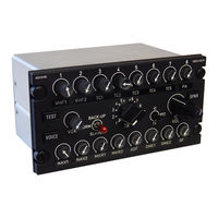
Becker ACU6100 series Installation And Operation Manual (48 pages)
Audio Control Unit
Brand:
Becker
| Category:
Control Unit
| Size: 3.93 MB
Table of Contents
Table of Contents
5
Installation and Operation
1
In Tro Duc Ti on
7
Application
7
Ge Ne Ral des Crip Ti on
8
Mechanical Description
8
Elec Tri Cal des Crip Ti on
8
Ge Ne Ral Functions
8
Identification of Article
11
Ty Pes of Auio con Trol Unit
11
Tech ni Cal Data
12
Po Wer Supp Ly
12
Con Trol Data Trans Fer ACU-REU
12
Me Cha ni Cal Data
12
Unit con Nec Tors
13
En VI Ron Men tal con DI Tions
13
Soft Wa Re
13
Approvals
14
En VI Ron Men tal Qua Li Fi Ca Ti on (EU RO CAE/RTCA ED-14D/DO-160D)
14
Sco Pe of de Li very
15
Tab Le of con Tents
17
Air Craft Wiring
19
General
19
In Spec Ti on Befo Re Installation
19
Me Cha ni Cal Installation
19
Connector Pin Assignments
22
Panel Illumination
22
Con Fi Gu Ra Ti on Soft Wa Re
24
Table of Contents
29
Description and Function of the Operating Controls and Indicators
31
Operating Controls
31
Operation
31
Operating Instructions
33
Preparations (Power-Up Test)
33
Individual Transceiver Channel Volume Adjustment
34
Main Volume Adjustment
34
Transceiver Monitoring
34
Transceiver Operation
34
Forced Monitoring
35
Selection of Dual Transmission Mode
35
Selection of Intercom PTT
35
Selection of Transmission Mode
35
Transmission Mode
36
Dual Transmission Mode
37
Individual Receiver Channel Volume Adjustment
38
Monitored RX-Channel Visualization
38
Receiver Operation
38
Reciever Monitoring
38
Loudspeaker Operation
39
Main Volume Adjustment
39
Voice Filter Activation
39
Intercommunication
41
Virtual Intercom Circuits
41
Cabin CALL/ISOL Functionality
42
Cockpit CALL/ISOL Functionality
42
Intercom Activation
42
External Switch Controlled Intercom
43
PTT Controlled Intercom
43
Voice Controlled Intercom
43
VOX Level Adjustment
43
IC Volume Adjustment
44
Winchman Intercom
44
Winchman VOX Level Functionality
44
Allocation of Selective CALL
45
Emergency CALL Function
45
Selective CALL Forced Monitoring
45
Selective CALL Function
45
Selective CALL Indication
45
Winchman Volume Level Functionality
45
Advertisement
Related Products
Becker ACU6100-x-Series
Becker active.5 LMU plus BE B10
Becker active.6 CE LMU BE B30
Becker active.6 LMU plus BE B40
Becker active.5 LMU BE B00
Becker active.5s EU
Becker Active.5sl EU
Becker Active.7sl EU
Becker Active 43 Transit
Becker Active 43 Traffic
Becker Categories
Water Pump
Transmitter
DC Drives
GPS
Air Compressor
More Becker Manuals
Login
Sign In
OR
Sign in with Facebook
Sign in with Google
Upload manual
Upload from disk
Upload from URL