Table of Contents
Advertisement
S30, S30-V..
Assembly and Operating Instructions
en
Door control unit
Important information for:
• Fitters / • Electricians / • Users
Please forward accordingly!
These instructions must be kept safe for future reference.
4023 630 402 0b 15/01/2018
Becker-Antriebe GmbH
Friedrich-Ebert-Straße 2-4
35764 Sinn/Germany
www.becker-antriebe.com
Advertisement
Table of Contents

Related Manuals for Becker S30


Summary of Contents for Becker S30
- Page 1 S30, S30-V.. Assembly and Operating Instructions Door control unit Important information for: • Fitters / • Electricians / • Users Please forward accordingly! These instructions must be kept safe for future reference. 4023 630 402 0b 15/01/2018 Becker-Antriebe GmbH Friedrich-Ebert-Straße 2-4 35764 Sinn/Germany www.becker-antriebe.com...
-
Page 2: Table Of Contents
Table of contents General ........................ 3 Warranty ...................... 3 Safety instructions .................... 4 Intended use ...................... 6 Abbreviations/symbols in these instructions............ 7 Assembly ...................... 8 Electrical connection..................... 9 Controls ...................... 10 Checking the running direction ................ 10 Setting the door limit positions ................ 11 Connection and function of external control sensors and safety devices .... 14 Setting the DIP switches .................. 18 Status indications .................... 18... -
Page 3: General
General This door control unit is a high-quality product with the following performance charac- teristics: • Evaluation of safety sensors on the door (e.g. closing edge surveillance, pull-in safety device and similar) • Evaluation of additional safety devices on the door (e.g. light barriers, light grids and similar) •... -
Page 4: Safety Instructions
Safety instructions The following safety instructions and warnings are intended to avert hazards and to prevent property damage and personal injury. It is important to follow these instruc- tions. General information • In addition to the fire and accident prevention regulations, the safety instructions given in EN 12453, EN 12445, EN 12978, VDE 0100, EN 50110, EN 60204, EN 50178, EN 60335 and ASR A1.7 must be ob- served. - Page 5 Operating notes • Do not allow children to play with permanently mounted regulating or control devices. • Keep remote control units out of the reach of children. • Systems have to be checked regularly by authorised specialists for wear and damage. •...
-
Page 6: Intended Use
• Operating the control unit with a detached CEE plug is only permiss- ible if the mains supply can be isolated from all poles of the control unit using an appropriate switch. The mains plug, or any switch used as a substitute, must be easily accessible. Caution •... -
Page 7: Abbreviations/Symbols In These Instructions
Abbreviations/symbols in these instructions Abbreviation / Description symbol Impulse button Light barrier Closing edge safety device Pressure monitor testing DW testing Electric safety edge Optical safety device Emergency Stop Pre-limit switch Automatic reclosing LED lights up LED off LED flashes... -
Page 8: Assembly
Assembly Do not select an assembly location exposed to electromagnetic fields, such as loca- tions in the direct vicinity of contactors (power relay), mains transformers, ignition transformers, fluorescent tubes, etc., or their connecting cables. Protect the control unit from direct sunlight and driving rain. Open the cover of the control unit. -
Page 9: Electrical Connection
3 x 10 A. Connecting the drive to the control unit To connect the Becker sectional door drive to the door control unit, connecting cables are available in a variety of lengths. The connecting cable has a plug-in cable gland on both sides. -
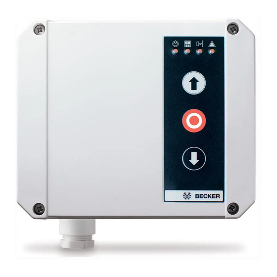
Page 10: Controls
Controls Labelling Function Function: Function: Brief actuation Actuation > 5 sec. OPEN OPEN command STOP If drive is in motion: STOP Confirmation of a fault, storage of a limit position If drive is at a halt: Light on/ off if light function with stopping time is set CLOSE CLOSE command... -
Page 11: Setting The Door Limit Positions
Setting the door limit positions Check whether the control unit is in learning mode. The control unit is in learning mode when all 4 LEDs are flashing and when there is no fault present. If not, proceed as fol- lows: 1. - Page 12 Description 4. For exact adjustment of the limit position, the control unit will move the door in inching mode, i.e., each time the OPEN/CLOSE buttons are pressed, the control unit will only move the door for approx. 50 ms. This allows for exact adjustment of the desired limit position.
- Page 13 Description 10a. If a safety edge is connected, you train the pre-limit switch as follows: Place the VES gauge or a similar implement (height: 30...40 mm, e.g. wooden slat, pipe or sim- ilar) on the ground under the door, in the middle of the clearance of the door opening.
-
Page 14: Connection And Function Of External Control Sensors And Safety Devices
Description 14. Now the setting of the limit positions is com- plete. To test the setting height of the internal VES pre-limit switch, place the VES gauge or a similar implement (height: 50 mm, e.g. wooden slat, pipe or similar) on the ground un- der the door, in the middle of the clearance of the door opening. - Page 15 External single push button An external single push button can be connected to terminals FE4 and 12V (IMP). With door control unit S30, S30-V2: The commands are executed one after the other in the sequence OPEN / STOP / CLOSE / STOP.
- Page 16 Light barrier A light barrier can be connected at the FE5 and 12V (LS) terminals. The jumper between terminals FE5 and 12V must be removed at installation. If the light barrier responds during travel in the DOWN direction, the door is brought to an immediate halt.
- Page 17 Type of safety edge DIP 1 DIP 2 DIP 3 Pneumatic safety edge 1.2 kΩ Pneumatic safety edge 8.2 kΩ Electric safety edge 1.2 kΩ Electric safety edge 8.2 kΩ Optoelectronic safety edge OSE Caution When using a pneumatic safety edge, the DIP switch 2 must always be set to the ON position, as otherwise it is not possible to properly monitor the function of the pneu- matic safety edge.
-
Page 18: Setting The Dip Switches
Setting the DIP switches Switch Position Function Electric or pneumatic safety edge is connected DIP 1 Optoelectronic safety edge OSE is connected Pneumatic safety edge (DW) connected, pressure wave test- DIP 2 ing is active Electric safety edge is connected Terminating resistance of the safety edge = 8.2 kΩ... - Page 19 Description Light barrier LS activated Light barrier LS negative testing Error running time exceeded, rota- tional error, blockage Stop, OPEN activated in limit position Control unit defective, internal error Emergency stop, slack rope activ- ated, drive command error Confirm by pressing and holding the Stop button Rotary encoder error Rotary encoder communication error...
-
Page 20: Maintenance
Only clean the outside of the housing with a suitable cloth. Do not use cleaning agents, as these may damage the plastic. Technical data Type S30, S30-V.. Mains connection 400 V 3~N PE 50 Hz Nominal motor rating max. 1.8 kW... - Page 21 Type S30, S30-V.. Secure functions Safety edge: SE1 Category 2 / PL c (EN ISO 13849-1:2008) Light barrier with Category 2 / PL c testing Emergency Stop Category 2 / PL c Relay Changeover contact potential-free 0.5 A / 12 VDC...
-
Page 22: Wiring
Wiring Mains connection S3F – Safety limit switch emergency operation S4F – Thermoswitch 3~400 V Membrane keypad 1 2 3 4 5 6 7 8 3 x 400 V AC / 50 - 60 Hz... - Page 23 Wiring assignment K1 and K2 GND 12V SE1 FE2 FE3 FE4 FE6 12V FE1 12V 12V FE5 GND NC...
-
Page 24: Declaration Of Conformity
Declaration of conformity...
Need help?
Do you have a question about the S30 and is the answer not in the manual?
Questions and answers