Table of Contents
Advertisement
BECK-O-TRONIC 6
Version: Centronic
Assembly and Operating Instructions
en
Door control unit
Important information for:
• Fitters / • Electricians / • Users
Please forward accordingly!
These instructions must be kept safe for future reference.
4005 630 202 0b 09/08/2018
Becker-Antriebe GmbH
Friedrich-Ebert-Straße 2-4
35764 Sinn/Germany
www.becker-antriebe.com
Advertisement
Table of Contents

Related Manuals for Becker Beck-O-Tronic 6


Summary of Contents for Becker Beck-O-Tronic 6
- Page 1 BECK-O-TRONIC 6 Version: Centronic Assembly and Operating Instructions Door control unit Important information for: • Fitters / • Electricians / • Users Please forward accordingly! These instructions must be kept safe for future reference. 4005 630 202 0b 09/08/2018 Becker-Antriebe GmbH Friedrich-Ebert-Straße 2-4...
-
Page 2: Table Of Contents
Table of contents General ........................ 3 Warranty ...................... 3 Safety instructions .................... 4 Intended use ...................... 6 Product overview .................... 7 Assembly ...................... 8 Wiring ........................ 9 Operator controls & functions/displays .............. 10 Parametrisation .................... 15 Menu table ...................... 16 Connections & functions.................. 22 Reset / factory setting .................. 29 Functional description .................. 30 Remote control .................... 34... -
Page 3: General
General This control unit is a high-quality product with many features and advantages: • Simple, convenient connection • Easy to handle and highly flexible • Automatic limit position detection • Defined buttons for OPEN, STOP and CLOSE, also on the hand-held transmitter •... -
Page 4: Safety Instructions
Safety instructions The following safety instructions and warnings are intended to avert hazards and to prevent property damage and personal injury. Please keep the instruction manual safe! Caution • Work on the electrical equipment may only be carried out by a qualified electrician. •... - Page 5 • If there is no fixed stop, e.g., when using roller doors, the customer must ensure that the roller shutter curtain is protected and cannot cause any dangerous situ- ations, e.g., by overrunning a limit position. • The control unit is designed to have a service life of 100,000 operating cycles.
-
Page 6: Intended Use
the control unit. In light of this, the installer / person re- sponsible for the system must carefully check the set- tings made and modify them as necessary. Intended use The type of control unit described in these instructions may only be used for the opera- tion of tubular drives in roller doors which have fixed stops at the limit positions or a cover on the barrel (EN 12453). -
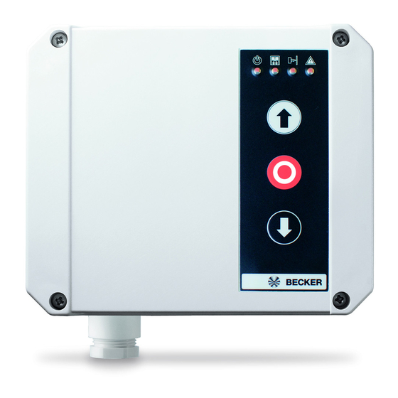
Page 7: Product Overview
Product overview Status display OPEN button STOP button CLOSE button Hand-held transmitter Mains plug Caution Work on the electrical equipment may only be carried out by a qualified electrician. -
Page 8: Assembly
Assembly Check that the transmitter and receiver are functioning perfectly prior to installation in the desired location. Do not choose an installation location that is exposed to electro- magnetic fields, e.g., in the immediate vicinity of contactors (power relays), mains transformers, ignition transformers, fluorescent tubes, etc., or their connecting cables. -
Page 9: Wiring
Wiring Connect the individual pieces of equipment as shown in the connecting diagram. Caution Electrical work may only be carried out by qualified elec- tricians or trained personnel. Always disconnect the safety mains plug before connecting the equipment. The connection to the building wiring system must be estab- lished in accordance with the Machinery Directive using an adequately sized mains disconnection device. -
Page 10: Operator Controls & Functions/Displays
Operator controls & functions/displays Explanation of abbreviations Abbreviation Description Bottom rail sensor; sensor of main closing edge safety device. De- tects obstructions when the door is lowering Light barrier; for use in buildings as monitoring device for door sys- tem and to control the automatic reclosing operation. Automatic reclosing;... - Page 11 Function of buttons Display [Ta.F] [Ta.+] [Ta.-] [Ta.M] [Ta.+] + value Change menu item and OPEN / STOP in OPEN direc- tion [Ta.-] - value Change menu item and CLOSE / STOP in CLOSE dir- ection [Ta.F] Radio button For programming / deleting radio settings [Ta.M] Menu button Menu selection / display of input status...
- Page 12 Display on left Segment status Door status Bars running up Running up Bars running down Running down A bar is at a standstill + Advance warning time running flashes with 50% on and 50% off Automatic reclosing Stay-open time run- ning Flashes Stay-open time after exiting light barrier...
- Page 13 Display on right Segment status Input Flashes Pre-limit switch actuated Item on right lights up Control unit sends status via transmit module Membrane keypad Labelling Function Function: Function: short press press > 5 s OPEN OPEN command Permanently open: Automatic reclosing, ex- ternal inputs and radio dis- abled.
- Page 14 Status indications The status indicator shows the current status of the control unit. You can find this above the OPEN button. Program radio Flashes 1-channel operation Fault in USA circuit Flashes Flashes Internal fault Flashes Flashes Flashes (no redundancy) Control unit defective (replacement neces- sary) Error, negative testing...
-
Page 15: Parametrisation
Caution If an internal error occurs (no redundancy), the system changes over to dead-man mode for safety reasons. The door can only be lowered via the CLOSE button at the control unit. Testing Pneumatic safety edges are tested for safety-related reasons during every downward movement. -
Page 16: Menu Table
If no changes in the menu values are possible, the entire control panel is protected against readjustment. Enable via item "Disable/enable parametrisation". The drive cannot operate during the adjustment. Menu table Basic values = factory setting Menu Menu Function / value Basic Setting item... - Page 17 Menu Menu Function / value Basic Setting item value values SAFETY INPUT SE1: FUNCTION Travel in CLOSE direc- Travel in OPEN direc- tion: tion: No effect No effect Stop No effect Reverse travel No effect Reopening No effect No effect Stop Stop Stop...
- Page 18 Menu Menu Function / value Basic Setting item value values SAFETY INPUT SE2: FUNCTION Travel in CLOSE direc- Travel in OPEN direc- tion: tion: No effect No effect Stop No effect Reverse travel No effect Reopening No effect No effect Stop Stop Stop...
- Page 19 Menu Menu Function / value Basic Setting item value values LIGHT / WARNING LIGHT Only during advance warning time and drive oper- ation 01..60 Light time 10...600 s, in 10 s increments Display: On, if the door is in the OPEN limit position Display: On, if the door is in the CLOSE limit posi- tion Display: On, if the door is not in the OPEN limit po-...
- Page 20 Menu Menu Function / value Basic Setting item value values OPEN INPUT & MEMBRANE-TYPE KEY Travel in the OPEN direction with panic function Travel in the OPEN direction without panic function Dead-man function CLOSE INPUT & MEMBRANE-TYPE KEY Travel in CLOSE direction with panic function Travel in CLOSE direction without panic function Dead-man function PRE-LIMIT SWITCH...
- Page 21 Menu Menu Function / value Basic Setting item value values MAINTENANCE INTERVAL No maintenance interval 01..99 Maintenance interval 100…9,900 door move- ments, in increments of 100 No function Disable/enable parametrisation Menu items adjustable Menu items not adjustable Changeover: Press EMERGENCY STOP, [Ta.+ ] and [Ta.-] simul- taneously, Toggle between 00 and 01 with [Ta.M] Version number (only readable)
-
Page 22: Connections & Functions
Connections & functions Mains connection [Kl.1]..[Kl.2] Protective conductor / PE [Kl.3] L-conduction [Kl.4] N-conductor Light / warning light [Kl.1]..[Kl.2] Protective conductor / PE [Kl.5] L-conductor (enabled) [Kl.6] N-conductor (enabled) • 230 V / AC output, max. 250 VA, all-pole disconnection •... - Page 23 Drive / tubular drive • The drive must travel in the OPEN direction following "Operating voltage / mains voltage on" and the first pulse command. If the drive travels in the CLOSE direc- tion even though the bars in the display are moving up, the connecting wires [Kl.7]+[Kl.8] must be swapped round.
- Page 24 12 V DC output (stabilised) [Kl.18] 0V / Earth [Kl.20] 0V / Earth Connection for external consumer, e.g., OSE, light barrier, etc. Attention! The maximum current specified in the "Technical data" must not be exceeded! Non-compliance can lead to malfunctions, failure, destruction and property damage.
- Page 25 Safety input • When the automatic reclosing is active and the SE input is actuated, the stay- open time is reset until the input is once again enabled. • The input has a safety function and is monitored by self-testing of the electronics. If an error is detected in the SE input, door travel is not possible.
- Page 26 Safety input SE1 (LS / 1k2 / 8K2 / OSE) [M.A2] 05: Standard OSE [M.A2] 06: 400 Hz [Kl.11] +12 V (brown) [Kl.18] or [Kl.20] Earth (white) [Kl.13] Signal (green) LS connection without external testing [M.A2] [Kl.11] LS: +12V [Kl.18] or [Kl.20] Earth [Kl.13] and [Kl.14] Relay output LS...
- Page 27 Safety input SE2 (LS / 1k2 / 8K2 / OSE) [Kl.18] or [Kl.20] Earth (white) [Kl.15] Signal (green) LS connection without external testing [M.A4] [Kl.11] LS: +12V [Kl.18] or [Kl.20] Earth [Kl.14] and [Kl.15] Relay output LS LS connection with external testing [M.A4] [Kl.12] LS transmitter: +12V...
- Page 28 OPEN input [Kl.16] OPEN input [Kl.18] 0V / Earth • Input for push-button, key-operated push-button, external radio, etc. • NO contact, floating • Several control sensors can be connected in parallel. • With [M.b3] = "dead-man function", radio operation for the corresponding direc- tion of travel is disabled.
-
Page 29: Reset / Factory Setting
Pulse input [Kl.19] Pulse input [Kl.20] 0V / Earth • Input for push-button, key-operated push-button, external radio, etc. • NO contact, floating • Several control sensors can be connected in parallel. • If the door is in the OPEN limit position, only the stay-open time is reset via a pulse or OPEN command. -
Page 30: Functional Description
Functional description Type of limit switch detection via running time or limit switch During commissioning, the type of limit position detection must be set in [M.A1]. • Running time switch off [M.A1] = 00 ∙ This operating mode may only be used with systems where there is no risk in- volved in doing so, or where this risk is safeguarded by another means. - Page 31 Drive / tubular drive operation • The control unit is ideally designed for tubular drives with internal limit switches that switch off the corresponding direction of travel directly. The control unit evaluates the drive current and can thus identify the limit positions. •...
- Page 32 • If switch-off via SE1 / SE2 occurs three times in succession during travel in the CLOSE direction, the automatic reclosing is blocked after the third unsuccessful at- tempt to travel in the CLOSE direction until the next pulse, OPEN, CLOSE or radio command.
- Page 33 Emergency operation - dead-man • If control sensors (1k2 / 8k2 / OSE / LS) at safety inputs SE1 / SE2 are defective, the control unit can be manually operated in dead-man mode in the OPEN or CLOSE direction. • Emergency operation can be controlled via the OPEN and CLOSE inputs, [Ta.+] / [Ta.-], and also the membrane keypad.
-
Page 34: Remote Control
Maintenance interval • The number of door movements (movements in OPEN direction) that elapse before the next maintenance message is displayed; set in [M.C5]. • The light output flashes when the drive is in operation to indicate that maintenance is due. •... - Page 35 Value Function {F1} Triple push-button, Open-Stop/Light-Close {F2} Pulse (Open-Stop-Close-..) Transmitter: {F1} Open-Stop/Light-Close {F2} Pulse Open button Button with Stop/Light button pulse sequence Close button Programming a transmitter: 1. Press [Ta.F] < 1 s until {F1} flashes in the display 2. Select the required function with [Ta.+] or [Ta.-] 3.
-
Page 36: Disposal
Deleting all transmitters 1. Press and hold the button [Ta.F] until {FL} flashes in the display after which the {FL} display goes off. 2. All codings have now been deleted. Antenna connection 1. An antenna wire must be connected to [Kl.23]. 2. -
Page 37: Cleaning
Cleaning Only clean the outside of the housing with a suitable cloth. Do not use cleaning agents, as these may damage the plastic. Error messages "Er" (Error) and the relevant error number flash alternately in the display to signal an er- ror. - Page 38 Error no. Description of error Comment / measure ROM test Switch off operating voltage, wait 10 s, switch operating voltage back on. If the error message persists, there is an error in the controller hardware. The control unit must be replaced. RAM test Switch off operating voltage, wait 10 s, switch operating voltage back on.
- Page 39 Error no. Description of error Comment / measure LS / SE1 (external test- Switch off operating voltage, wait 10 s, ing) switch operating voltage back on. If the error message persists: a) Check setting [M.A2] (external LS test) with regard to connected light barrier. b) Check connection of LS transmitter in accordance with item Safety input SE1 (LS / 1k2 / 8K2 / OSE).
-
Page 40: Complete Connecting Diagram
Complete connecting diagram Test 0V Vor-ES NOT- 230V Licht 230V Impuls LS/SE/OSE... -
Page 41: Electric Safety Edge And Light Barrier Connecting Diagram
Electric safety edge and light barrier connecting diagram... -
Page 42: Safety Edge Ose Connecting Diagram
Safety edge OSE connecting diagram Technical data Dimensions of the housing (W x H x D) 155 x 130 x 50 mm Housing material Degree of protection IP54, only for installation indoors Supply voltage 230 V / 50 Hz (connection type Y) Input power 6 V A Fuse... -
Page 43: Declaration Of Conformity
Declaration of conformity...
Need help?
Do you have a question about the Beck-O-Tronic 6 and is the answer not in the manual?
Questions and answers