Table of Contents
Advertisement
Quick Links
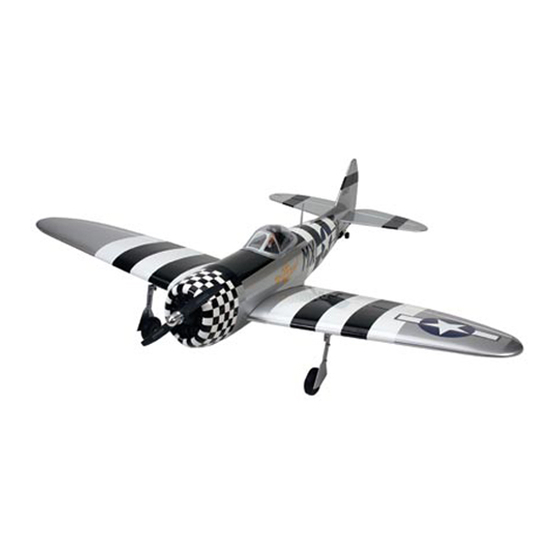
P-47 Thunderbolt
Specifications
Wingspan: ................................81.25 in (206.4 cm)
Wing Area: ......................1164 sq in (75.09 sq dm)
Length: ..........................................71 in (180.3 cm)
ASSEMBLY MANUAL
Weight: ............................. 15.5–17 lb (7.1–7.7 kg)
Radio: ................................. 6-channel w/10 servos
Recommended Engines: ...........1.20-2.20 4-stroke
�
��
...........1.20-2.10 2-stroke
................. 23cc-26cc gas
Advertisement
Table of Contents

Related Manuals for Hangar 9 P-47 thunderbolt


Summary of Contents for Hangar 9 P-47 thunderbolt
- Page 1 � �� P-47 Thunderbolt ASSEMBLY MANUAL Specifications Wingspan: ........81.25 in (206.4 cm) Weight: ......15.5–17 lb (7.1–7.7 kg) Wing Area: ......1164 sq in (75.09 sq dm) Radio: ......... 6-channel w/10 servos Length: ..........71 in (180.3 cm) Recommended Engines: ...1.20-2.20 4-stroke ...1.20-2.10 2-stroke...
-
Page 2: Table Of Contents
Table of Contents Table of Contents ..............2 Contents of Kit . -
Page 3: Contents Of Kit
Contents of Kit Large Parts: Small Parts: A. Wing Set HAN2702 Tail Wheel Assembly HAN2711 B. Fuselage HAN2701 Items Not Shown: C. Stabilizer Set w/Elevators HAN2703 Decal Set HAN2713 D. Canopy HAN2706 Pushrod Set HAN2710 E. Cowling HAN2705 Plastic Scale Detail Set HAN2712 F. -
Page 4: Additional Required Tools And Adhesives
Additional Required Tools and Adhesives Tools Adhesives • 6-Minute Epoxy (HAN8000) • Adjustable wrench • Hobby scissors • 30-Minute Epoxy (HAN8002) • Thin CA (PAAPT07) • Drill • Shoe Goo • Drill bits: 1/16", #43, 1/8", 7/64" • Felt-tipped pen •... -
Page 5: Before Starting Assembly
Before Starting Assembly Before beginning the assembly of your P-47 Thunderbolt, remove each part from its bag for inspection. Closely inspect the fuselage, wing panels, rudder, and stabilizer for damage. If you find any damaged or missing parts, contact the place of purchase. -
Page 6: Section 1 - Aileron Installation
Section 1 – Aileron Installation Required Parts Step 3 • Right and left wing panels w/ailerons Slide the aileron onto the wing until there is only a slight • CA hinges (6) gap between the aileron and wing panel. Remove the T-pins and snug the aileron against the wing panel. - Page 7 Section 1 – Aileron Installation Step 5 Step 8 Turn the wing panel over, deflect the aileron in the Work the aileron up and down several times to work in the opposite direction and apply thin CA to the other side of hinges and check for proper movement.
-
Page 8: Section 2 - Aileron Servo Installation
Section 2 – Aileron Servo Installation Required Parts Step 2 • Wing assembly Install the recommended servo hardware (grommets and • Control horn (2) • Mounting screws (6) eyelets) supplied with the servo. Install a long half servo •... - Page 9 Section 2 – Aileron Servo Installation Note: Before mounting the servo, it is Note: It is always a good idea to secure the suggested to electronically center the servo servo connector and servo extension together using the transmitter, then install the servo arm to prevent the wires from becoming unplugged to avoid having to remove the servo and center inside the wing.
- Page 10 Section 2 – Aileron Servo Installation Step 9 Step 11 Thread a clevis onto the end of the threaded rod. The Attach the clevis to the control horn. Position the control threaded rod should just be visible between the forks on the aileron by aligning the linkage with the servo arm of the clevis.
- Page 11 Section 2 – Aileron Servo Installation Step 13 Step 14 Install one of the #2 x 1/2" screws into a hole drilled, Attach the control horn using three #2 x 1/2" screws. then remove it. Place 2–3 drops of thin CA into the hole to harden the wood.
-
Page 12: Section 3 - Flap Installation
Section 3 – Flap Installation Required Parts Step 3 • Wing assembly • Nylon flap hinges (6) Install the hinges in the flap and slide the flap into position. Check to make sure the flap aligns with both the Required Tools and Adhesives aileron and wing trailing edge. - Page 13 Section 3 – Flap Installation Note: Pacer hinge glue can be used instead of Step 4 epoxy for gluing the flap hinges. Use 30-minute epoxy to install the hinges. Apply epoxy to both the holes in the flap and wing using a toothpick. ...
-
Page 14: Section 4 - Flap Servo Installation
Section 4 – Flap Servo Installation Required Parts Step 3 • Wing assembly • Flap linkage (2) Place the flap servo between the mounting blocks so the • Flap servo hatch (2) • Wire keeper (2) output spline will be towards the leading edge of the wing. Center the servo using the radio. - Page 15 Section 4 – Flap Servo Installation Step 6 Step 8 Prepare the flap linkage by threading a 4-40 clevis onto Attach the flap linkage to the servo arm using the pushrod. Bend the rod at a 90-degree angle 3 "...
-
Page 16: Section 5 - Retract Installation
Section 5 – Retract Installation Required Parts Step 3 • Right and left wing panels Attach the servo horn to the retract servo. It is • 4-40 x 1/4" screw (2) • Metal clevis (2) positioned so the arm moves from one end of the •... - Page 17 Section 5 – Retract Installation Step 5 Step 6 Check that the retract fully locks at both up and down Once the retracts are fully adjusted, install them positions without stalling the servo. Adjust the length of into the wing and secure their position using four the linkage and the position of the linkage at the servo 6-32 x 1/2"...
-
Page 18: Section 6 - Hinging The Elevators
Section 6 – Hinging the Elevators Required Parts Step 3 • Stabilizer • CA hinges (6) Deflect the elevator and apply thin CA to the hinge. Apply • Elevator (right and left) enough CA to completely saturate both the top and bottom of the hinge. -
Page 19: Section 7 - Rudder Installation
Section 7 – Rudder Installation Required Parts Step 2 • Fuselage assembly • Rudder Slide the rudder onto the fin. Align the top of the rudder • CA hinges (3) with the top of the fin. Remove the T-pins and use thin CA to glue the hinges into position. -
Page 20: Section 8 - Wing And Stabilizer Installation
Section 8 – Wing and Stabilizer Installation Required Parts Step 4 • Wing panels • Fuselage Secure the wing panels using the 1/4-20 x 2" nylon wing • Wing tube • Stabilizer tube bolts. • Tap handle • 4-40 tap •... - Page 21 Section 8 – Wing and Stabilizer Installation Step 6 Step 7 Drill through the hole into the stabilizer and tap for a Slide the assembly into the fuselage. Slide the 4-40 bolt. Install a 4-40 x 1/2" bolt to secure the tube remaining stab half onto the tube and drill and tap in the stabilizer.
-
Page 22: Section 9 - Tail Wheel Installation
Section 9 – Tail Wheel Installation Required Parts Step 2 • Tail gear wire • Tail gear steering arm Attach the brass connector to the inside hole of the • Tail gear mount • Tail gear support steering arm using the connector backplate. •... - Page 23 Section 9 – Tail Wheel Installation Step 4 Step 6 Position the mount inside the fuselage. The mount will Use two 1/8" wheel collars and two 3mm set screws to only fit in one direction. Once placed, secure the mount secure the tail wheel.
-
Page 24: Section 10A - Saito
Section 10A – Saito Engine Installation ™ Required Parts Note: The engine mount is embossed with the correct orientation for the mounts. • Fuselage • Engine mount (2) • #8 lock washers (8) • Engine Step 3 • Brass connector •... -
Page 25: Section 10B - Zenoah
Section 10B – Zenoah Engine Installation ® Required Parts Step 2 • Fuselage • Engine Use a 5/32" drill bit to drill the locations marked in • 8-32 x 1 " screws (4) • Felt-tipped pen the previous step. •... -
Page 26: Section 11 - Fuel Tank Installation
Section 11 – Fuel Tank Installation Required Parts Step 2 • Assembled Fuel Tank • Fuselage Position the tank inside the fuselage. The tank rests securely in the mounts inside the fuselage. Required Tools and Adhesives • Hobby knife •... -
Page 27: Section 12 - Radio Installation
Section 12 – Radio Installation Required Parts Step 3 • Fuselage assembly • 1/4” foam Wrap the receiver and receiver battery in 1/4" foam. • Receiver • Receiver battery Attach the receiver and battery to the radio tray using hook and loop material. -
Page 28: Section 13 - Linkage Installation
Section 13 – Linkage Installation Required Parts Step 3 • Fuselage assembly • Pushrod wires (3) Remove the back plate from a control horn using side • Nylon clevis (3) • Clevis keeper (3) cutters or a sharp hobby knife. Use a 1/8" drill bit to drill •... - Page 29 Section 13 – Linkage Installation Step 6 Step 9 Install one of the #2 x 1/2" screws in a hole drilled, and Bend the wire 90 degrees at the mark made in the then remove it. Place 2–3 drops of thin CA into the hole previous step.
- Page 30 Section 13 – Linkage Installation Step 12 Step 14 Center the tail wheel. Use a 3mm x 6mm screw to secure Center the throttle stick and trim with both the receiver the brass connector to the rudder wire. and transmitter on.
-
Page 31: Section 14 - Final Assembly
Section 14 – Final Assembly Required Parts Step 2 • Fuselage assembly • Cowl Install the propeller and spinner. • Decal sheet • Painted canopy • 4-40 x 1/2” socket head screws (10) • #4 washers (6) • Bomb assembly (2) •... - Page 32 Section 14 – Final Assembly Step 4 Step 8 Glue the canopy to the fuselage using RC560 canopy glue. Locate the positions for the pylon mounting screws on Tape the canopy in place with masking tape and allow the the bottom of the wing.
- Page 33 Section 14 – Final Assembly Step 10 Step 12 Attach the bomb/pylon assembly to the wing using Attach the bomb to the wing using the screws. the two screws. Step 13 Step 11 Glue the cap on the end of the bomb. lide the two 4-40 x 1/2"...
- Page 34 Section 14 – Final Assembly Step 14 Step 15 Locate the mounting holes for the drop tank and remove Secure the tank to the fuselage using the two drop tank the covering. The drop tank is positioned as shown. screws and drop tank fairing.
-
Page 35: Control Throws
Control Throws The amount of control throw should be adjusted as closely as possible using mechanical means, rather than making large changes electronically at the radio. By moving the position of the clevis at the control horn toward the outermost hole, you will decrease the amount of control throw of the control surface. -
Page 36: Adjusting The Engine
Adjusting the Engine Step 1 Completely read the instructions included with your engine and follow the recommended break-in procedure. Step 2 At the field, adjust the engine to a slightly rich setting at full throttle and adjust the idle and low-speed needle so that a consistent idle is achieved. -
Page 37: Preflight At The Field
Preflight at the Field Range Test Your Radio Step 3 Double-check that all controls (aileron, elevator, rudder, Step 1 and throttle) move in the correct direction. Before going to the field, be sure that your batteries are fully charged, per the instructions included with ... -
Page 38: 2005 Official Ama National Model Aircraft Safety Code
2005 Official AMA National Model Aircraft Safety Code GENERAL 7) I will not operate models with pyrotechnics (any device that explodes, burns, or propels a projectile 1) I will not fly my model aircraft in sanctioned of any kind) including, but not limited to, rockets, events, air shows or model flying demonstrations until explosive bombs dropped from models, smoke it has been proven to be airworthy by having been... - Page 39 2005 Official AMA National Model Aircraft Safety Code 5) Flying sites separated by three miles or more Organized RC Racing Event are considered safe from site-to site interference, 10) An RC racing event, whether or not an AMA Rule even when both sites use the same frequencies. Any Book event, is one in which model aircraft compete circumstances under three miles separation require in flight over a prescribed course with the objective of...
- Page 40 � �� © 2005 Horizon Hobby, Inc. 4105 Fieldstone Road Champaign, Illinois 61822 (877) 504-0233 horizonhobby.com 7335...
Need help?
Do you have a question about the P-47 thunderbolt and is the answer not in the manual?
Questions and answers