Table of Contents
Advertisement
Quick Links
Download this manual
See also:
Quick Manual
Advertisement
Table of Contents

Related Manuals for AG Neovo DR-22


Summary of Contents for AG Neovo DR-22
-
Page 2: Table Of Contents
TABLE OF CONTENTS Contents Safety Information FCC Declaimers ............................4 WEEE ............................... 5 Precautions Notice ............................... 7 Cautions When Setting Up ........................7 Cautions When Using ..........................8 Cleaning and Maintenance ........................8 Symbol Meaning ............................8 Notice for the LCD Display ........................9 Chapter 1: Product Description 1.1 Package Contents .......................... - Page 3 TABLE OF CONTENTS Chapter 5: Adjusting the Settings 5.1 Brightness Setting ..........................29 5.2 Colour Setting ............................. 31 5.3 Image Setting (PC Source only) ......................32 5.4 Image Setting (Video signals) ......................33 5.5 Aspect Ratio Setting ........................... 35 5.6 PIP Setting ............................37 5.7 OSD Setting ............................
-
Page 4: Safety Information
Safety Information SAFETY INFORMATION This FCC Class-B compliant digital device complies with the Interference-Causing Equipment Regulations of Canada. FCC Declaimers This device complies with Section 15 of the FCC listing. The operation procedures must meet the following conditions: (1) the device must not cause any damaging interference; and (2) this device must accept any received interference, including any unpredictable interference that may possibly occur. -
Page 5: Weee
IEC 61000-4-11: 2004 Guidance and manufacturer’s declaration – electromagnetic emissions The model DR-22 is intended for use in the electromagnetic environment specified below. The customer or the user of the model DR-22 should assure that it is used in such an environment. - Page 6 RF communications equipment and the model DR-22 The model DR-22 is intended for use in an electromagnetic environment in which radiated RF disturbances are controlled. The customer or the user of the model DR-22 can help prevent electromagnetic interference...
-
Page 7: Precautions
Precautions PRECAUTIONS CAUTION RISK OF ELECTRIC SHOCK DO NOT OPEN Symbols used in this manual This icon indicates the existence of a potential hazard that could result in personal injury or damage to the product. This icon indicates important operating and servicing information. Notice •... -
Page 8: Cautions When Using
AG Neovo for consultations and Symbol Meaning solutions to help ensure a most pleasurable and fulfilling display IEC 60417-5031 Direct current experience. -
Page 9: Notice For The Lcd Display
This is acceptable and is not considered a failure. The intended use of the DR-22 is to serve as a LCD monitor for integration with the hospital system. It is designed for general purpose for hospital environment. For displaying and viewing of images for reference. - Page 10 PRECAUTIONS Notice for the LCD Display Use a power cord that matches the voltage of the power outlet, which has been approved and complies with the safety standard of your particular country. WARNING – Do not modify this equipment without authorization of the manufacturer. WARNING –...
-
Page 11: Chapter 1: Product Description
CHAPTER 1: PRODUCT DESCRIPTION 1.1 Package Contents When unpacking, check if the following items are included in the package. If any of them is missing or damaged, contact your dealer. LCD Display User Manual Power adapter Power cord VGA cable Audio cable Warranty card Note:... -
Page 12: Wall Mounting Installation Preparation
75mm other horizontal surface overhead are strongly advised to contact AG Neovo for consultations and solutions to help ensure a most pleasurable and fulfilling display experience. 1.2.2 Removing the Base Stand... -
Page 13: Lcd Display Overview
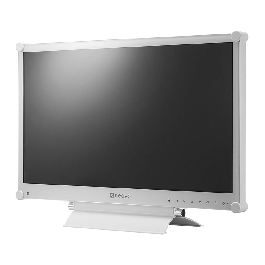
PRODUCT DESCRIPTION 1.3 LCD Display Overview 1.3.1 Front View and Keypad Buttons POWER / AUTO ADJ. SWAP/ MENU INPUT DOWN SELECT ROTATE SELECT Display screen The LCD display screen is protected by • Press repeatedly to select PIP option. NeoV Optical Glass. -
Page 14: Rear View
PRODUCT DESCRIPTION 1.3.2 Rear View S-VIDEO CVBS-1 CVBS-2 AUDIO DC IN HDMI AUDIO IN DC power input Audio port Use to connect the power cord. Use to connect an audio cable for the PC’s audio input. HDMI connector S-Video connector Use to connect an input device using Use to connect AV cables for the HDMI cable for digital input signal. -
Page 15: Chapter 2: Making Connections
CHAPTER 2: MAKING CONNECTIONS 2.1 Connecting the Power Connect the power cord to the power adapter. Connect the power adapter to the DC power input at the rear of the LCD display. Connect the power cord plug to a power outlet or a power supply. DC IN Caution: ♦... -
Page 16: Connecting Input Source Signals
MAKING CONNECTIONS 2.2 Connecting Input Source Signals 2.2.1 Connecting a Computer Using VGA Cables Connect one end of a D-sub cable to the VGA connector of the LCD display and the other end to the D-sub connector of the computer. Using DVI Cables Connect one end of a DVI cable to the DVI connector of the LCD display and the other end to the DVI connector of the computer. -
Page 17: Connecting An Audio Device
MAKING CONNECTIONS Connecting an Audio Device Connect one end of an audio cable to the audio port at the rear of the LCD display and the other end to the audio out port of the computer. AUDIO IN 2.2.2 Connecting a Camera or Video Device Using CVBS Cables Connect one end of a CVBS cable to the COMPOSITE connectors of... -
Page 18: Using S-Video Cables
MAKING CONNECTIONS Using S-Video Cables Connect one end of an S-Video S-VIDEO cable to the S-VIDEO connector of the LCD display and the other end to the S-VIDEO connector of your device. For audio input, connect an RCA cable to the audio in connector of the LCD display and the audio out connector of your device. -
Page 19: Chapter 3: Using The Lcd Display
CHAPTER 3: USING THE LCD DISPLAY 3.1 Turning on the Power Note: ♦ The LCD display still consumes POWER button power as long as the power LED indicator cord is connected to the power outlet. Disconnect the power Plug the power cord to a power outlet or power supply. cord to completely cut off power. -
Page 20: Adjusting The Volume / Illuminator Function Hot Key
USING THE LCD DISPLAY 3.3 Adjusting the Volume / Illuminator Function Hot Key VOLUME buttons Adjusting the Volume Touch either the buttons to call out the volume bar. Touch the button to increase volume or the button to decrease volume. To mute the audio, set the volume to 0. -
Page 21: Using Picture-In-Picture (Pip)
USING THE LCD DISPLAY 3.5 Using Picture-in-Picture (PIP) The Picture-in-Picture (PIP) feature allows viewing of more than one input source signal on the LCD display. 3.5.1 PIP Options Touch the button repeatedly to enable and scroll among the PIP options. Options are as follows: •... -
Page 22: Pip Swap
USING THE LCD DISPLAY 3.5.2 PIP Swap The main and the sub source signals set in PIP Setting can be easily swapped using the keypad. Note: ♦ PIP Swap can only be executed if PIP is enabled, see page 33. Main source Sub source Touch the... -
Page 23: Using Auto Adjustment Function
USING THE LCD DISPLAY 3.7 Using Auto Adjustment Function Note: Auto Adjustment function automatically tunes the LCD display to its optimal setting, including horizontal position, vertical position, clock, ♦ Auto Adjustment function is and phase. available only during VGA input signals. -
Page 24: Chapter 4: On Screen Display Menu
CHAPTER 4: ON SCREEN DISPLAY MENU 4.1 Using the OSD Menu Operation Display the main menu screen. Touch N T S C 6 0 H z B R I G H T N E S S B R I G H T N E S S C O N T R A S T C O L O U R S E T T I N G... - Page 25 ON SCREEN DISPLAY MENU Operation Select the submenu item. Touch the buttons. 6 0 H z B R I G H T N E S S T N E S S C O N T R A S T S E T T I N G B L A C K L E V E L S E T T I N G...
-
Page 26: Osd Menu Tree
ON SCREEN DISPLAY MENU 4.2 OSD Menu Tree N T S C 6 0 H z B R I G H T N E S S B R I G H T N E S S C O N T R A S T C O L O U R S E T T I N G B L A C K... - Page 27 ON SCREEN DISPLAY MENU Main Menu Submenu Remarks Image Setting During Video input signal: See page 33. • Sharpness • Saturation • Tint • 3D Comb Filter • Noise Reduction • Aspect Ratio • H. Zoom • V. Zoom • H. Position •...
- Page 28 ON SCREEN DISPLAY MENU Main Menu Submenu Remarks 10. Input Select • VGA See page 44. • DVI • HDMI • CVBS1 • CVBS2 • S-Video 11. Language Select the OSD language: EN / FR / DE / ES / IT / PY / RO / PL / CS / NL / 簡中...
-
Page 29: Brightness Setting
CHAPTER 5: ADJUSTING THE LCD DISPLAY 5.1 Brightness Setting 1. Touch to call out the OSD window. N T S C 6 0 H z B R I G H T N E S S B R I G H T N E S S 2. - Page 30 ADJUSTING THE LCD DISPLAY Original Setting High Setting Low Setting Brightness Contrast Black Level...
-
Page 31: Colour Setting
ADJUSTING THE LCD DISPLAY 5.2 Colour Setting 1. Touch to call out the OSD window. N T S C 6 0 H z C O L O U R T E M P . 6 5 0 0 K B R I G H T N E S S 2. -
Page 32: Image Setting (Pc Source Only)
ADJUSTING THE LCD DISPLAY 5.3 Image Setting (PC Source only) Note: Some submenu items are not available in DVI input source signal. 1. Touch to call out the OSD window. 1 0 2 4 x 7 6 8 6 0 H z S H A R P N E S S B R I G H T N E S S 2. -
Page 33: Image Setting (Video Signals)
ADJUSTING THE LCD DISPLAY 5.4 Image Setting (Video signals) 1. Touch to call out the OSD window. N T S C 6 0 H z S H A R P N E S S B R I G H T N E S S 2. - Page 34 ADJUSTING THE LCD DISPLAY Range / Item Function Operation Value Adjusts the noise reduction to help remove noise from images. This Touch the buttons to Noise Reduction helps produce clearer and crisper select the value. High images. Noise Reduction Off Noise Reduction On Overscan Adjusts the aspect ratio of the screen...
-
Page 35: Aspect Ratio Setting
ADJUSTING THE LCD DISPLAY 5.5 Aspect Ratio Setting Note: Overscan is available only in VGA and HDMI input source signals. 1. Touch to call out the OSD window. N T S C 6 0 H z A S P E C T R A T I O U N D E R S C A N B R I G H T N E S S... - Page 36 ADJUSTING THE LCD DISPLAY Range / Item Function Operation Value H. Zoom Adjusts the horizontal zoom. (Horizontal Zoom) Touch the buttons to 0 to 100 adjust the value. V. Zoom Adjusts the vertical zoom. (Vertical Zoom)
-
Page 37: Pip Setting
ADJUSTING THE LCD DISPLAY 5.6 PIP Setting 1. Touch to call out the OSD window. N T S C 6 0 H z P I P O F F P I P P A P B R I G H T N E S S 2. - Page 38 ADJUSTING THE LCD DISPLAY Note: Any input signal may be set as the main or the sub source signal. However, some input signals are not supported to be paired together as the main and the sub source signals. Refer to the following table for compatibility options. Table 5.1 PIP Compatibility Table Main HDMI...
-
Page 39: Osd Setting
ADJUSTING THE LCD DISPLAY 5.7 OSD Setting 1. Touch to call out the OSD window. N T S C 6 0 H z T R A N S P A R E N C Y B R I G H T N E S S 2. -
Page 40: Audio Setting
ADJUSTING THE LCD DISPLAY 5.8 Audio Setting 1. Touch to call out the OSD window. N T S C 6 0 H z A U D I O O F F B R I G H T N E S S 2. -
Page 41: Other Setting
ADJUSTING THE LCD DISPLAY 5.9 Other Setting 1. Touch to call out the OSD window. N T S C 6 0 H z P O W E R S A V I N G O F F B R I G H T N E S S 2. - Page 42 ADJUSTING THE LCD DISPLAY Range / Item Function Operation Value Activates the DDC/CI protocol to allow users Touch the buttons to DDC/CI to configure the monitor by a software using select the value. two wires on the VGA or DVI cables. Activates DCR.
-
Page 43: Auto Brightness
ADJUSTING THE LCD DISPLAY 5.10 Auto Brightness 5.10.1 EcoSmart Sensor With the built-in EcoSmart sensor, users can enable the Auto Brightness feature to automatically adjust the LCD screen brightness according to the ambient light. This feature comforts the eyes and helps optimise energy efficiency. -
Page 44: Input Select
ADJUSTING THE LCD DISPLAY 5.11 Input Select 1. Touch to call out the OSD window. N T S C 6 0 H z V G A P R E S S B R I G H T N E S S 2. -
Page 45: Chapter 6: Appendix
CHAPTER 6: APPENDIX 6.1 Warning Messages Warning Messages Cause Solution The resolution or the refresh rate of • Change the resolution or the the graphics card of the computer refresh rate of the graphics I N P U T S I G N A L O U T O F R A N G E is set too high. -
Page 46: Troubleshooting
APPENDIX 6.2 Troubleshooting Problem Possible Cause and Solution No picture. • Check if the LCD display is turned ON. • Check if the power cord is properly connected to the LCD display. • LED indicator is OFF. • Check if the power cord is plugged into the power outlet. •... - Page 47 APPENDIX Problem Possible Cause and Solution Faint shadows from a • Turn off the LCD display for extended periods of time. static image appear on the • Use a screen saver or a black and white image and run it for extended screen.
-
Page 48: Transporting The Lcd Display
APPENDIX 6.3 Transporting the LCD Display To transport the LCD display for repair or shipment, place the display in its original packaging carton. Put all the accessories in the box (if necessary). Place the two foam cushions on each side of the LCD display for protection. Place the LCD display down in the box. -
Page 49: Chapter 7: Specifications
CHAPTER 7: SPECIFICATIONS 7.1 Display Specifications DR-22 Panel Panel Size 21.5” Max. Resolution FHD 1920 x 1080 Pixel Pitch 0.2482 mm Brightness 250cd/m Contrast Ratio 2,000,000:1 (DCR) Viewing Angle (H/V) 170°/160° (Typical) Display Colour 16.7M Response Time 3ms (GTG) Frequency (H/V) -
Page 50: Display Dimensions
SPECIFICATIONS 7.2 Display Dimensions 282.4mm 53.5mm 32.6mm 100mm 513.2mm 368.5mm 324.3mm 100mm 75mm 75mm 155mm 227.4mm Company Address: 5F-1, No. 3-1, Park Street, Nangang District, Taipei, 11503, Taiwan.
Need help?
Do you have a question about the DR-22 and is the answer not in the manual?
Questions and answers