Table of Contents
Advertisement
Quick Links
Advertisement
Table of Contents

Related Manuals for AG Neovo DR-17G


Summary of Contents for AG Neovo DR-17G
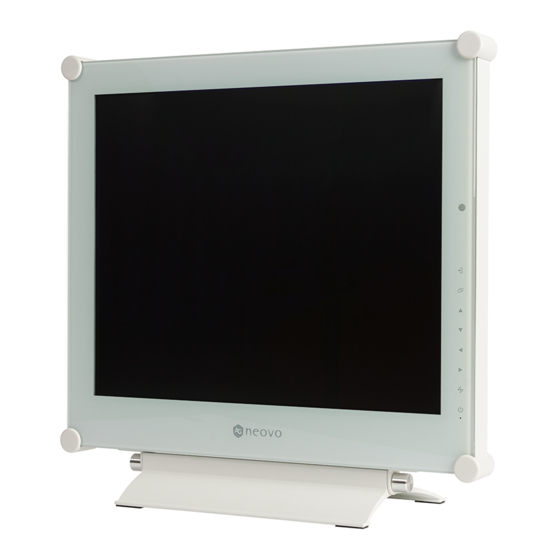
- Page 1 DR-17G & DR-22G LCD Monitor User Manual displays.agneovo.com...
-
Page 2: Table Of Contents
TABLE OF CONTENTS Safety Information Federal Communications Commission (FCC) Notice (U.S. Only) ............4 WEEE ............................... 5 EMC Information ............................6 Precautions Notice ............................... 10 Cautions When Setting Up ........................11 Cautions When Using ..........................12 Cleaning and Maintenance ........................13 Notice for the LCD Display ........................ - Page 3 6.1 Warning Messages ..........................57 6.2 Supported Resolutions ........................58 6.3 Troubleshooting ..........................59 6.4 Transporting the LCD Display ......................61 Chapter 7: Specifications 7.1 Display pecifications ........................62 7.2 Display Dimensions ..........................63 7.2.1 DR-17G Dimensions ....................... 63 7.2.2 DR-22G Dimensions ....................... 63...
-
Page 4: Safety Information
SAFETY INFORMATION Safety Information Federal Communications Commission (FCC) Notice (U.S. Only) This equipment has been tested and found to comply with the limits for a Class B digital device, pursuant to part 15 of the FCC Rules. These limits are designed to provide reasonable protection against harmful interference in a residential installation. -
Page 5: Weee
SAFETY INFORMATION WEEE Information for users applicable in European Union countries. The symbol on the product or its packaging signifies that this product has to be disposed separately from ordinary household wastes at its end of life. Please kindly be aware that this is your responsibility to dispose electronic equipment at recycling centers so as to help conserve natural resources. -
Page 6: Emc Information
Guidance and manufacturer’s declaration – electromagnetic emissions The DR-17G and DR-22G is intended for use in the electromagnetic environment specified below. The customer or the user of the DR-17G and DR-22G should assure that it is used in such an environment. Not Life-supporting Medical Equipment. - Page 7 Guidance and manufacturer’s declaration – electromagnetic immunity The DR-17G and DR-22G is intended for use in the electromagnetic environment specified below. The customer or the user of the DR-17G and DR-22G should assure that it is used in such an environment. Not Life-supporting Medical Equipment.
- Page 8 Guidance and manufacturer’s declaration – electromagnetic immunity The DR-17G and DR-22G is intended for use in the electromagnetic environment specified below. The customer or the user of the DR-17G and DR-22G should assure that it is used in such an environment. Not Life-supporting Medical Equipment.
- Page 9 Recommended separation distances between portable and mobile RF communications equipment and the DR-17G and DR-22G The DR-17G and DR-22G is intended for use in an electromagnetic environment in which radiated RF disturbances are controlled. The customer or the user of the DR-17G and DR-22G can help prevent...
-
Page 10: Precautions
PRECAUTIONS Precautions CAUTION RISK OF ELECTRIC SHOCK DO NOT OPEN Symbols used in this manual This icon indicates the existence of ISO 7010-M002: Follow instructions a potential haz a rd that could result for use in personal injury or damage to the product. -
Page 11: Cautions When Setting Up
PRECAUTIONS Cautions When Setting Up Do not place the LCD display near heat sources, such as a heater, exhaust vent, or in direct sunlight. Do not cover or block the ventilation holes in the housing. Place the LCD display on a stable area. Do not place the LCD display where it may subject to vibration or shock . -
Page 12: Cautions When Using
Users who have already mounted the display on the ceiling or any other horiz o ntal surface overhead are strongly advised to contact AG Neovo for consultations and solutions to help ensure a most pleasurable and fulfilling display experience. -
Page 13: Cleaning And Maintenance
This is acceptable and is not considered a failure. The intended use of the DR-17G, DR-22G is to serve as a LCD monitor for integration with the hospital system.It is designed for general purpose for adults using at hospital environment,continuous operation. For displaying and viewing of images for reference. - Page 14 PRECAUTIONS Notice for the LCD Display Accessory equipment connected to the analog and digital interfaces must be in compliance with the respective nationally harmoniz e d IEC standards (i.e. IEC 60950 for data processing equipment, IEC 60065 for video equipment, IEC 61010-1 for laboratory equipment, and IEC 60601-1 for medical equipment). Furthermore all configurations shall comply with the system standard IEC 60601-1.
-
Page 15: Chapter 1: Product Description
Power adapter Must use only the supplied power adapter: DR-17G & DR-22G ♦ ADAPTER TECH Quick Start Guide Model no.: ATM065T-P240 DR-17G & DR-22G LCD Monitor Rating: 24V/2.71A DR-17G/DR-22G_Quick Guide_V010 displays.agneovo.com Power cord VGA cable Audio cable Warranty card Note: ♦... -
Page 16: Wall Mounting Installation Preparation
75mm display on the ceiling or any other horiz o ntal surface overhead are strongly advised to contact DR-17G AG Neovo for consultations and solutions to help ensure a most 100mm pleasurable and fulfilling display experience. Note:... -
Page 17: Removing The Base Stand
Removing the Base Stand ay the CD display face down on a flat even surface. Note: Remove the screws* securing the base stand from the LCD (*) The screw siz e is M4 x 10mm. display. Detach the base stand. DR-17G DR-22G... -
Page 18: Lcd Display Overview
PRODUCT DESCRIPTION 1.3 LCD Display Overview 1.3.1 Front View and Keypad Buttons DR-17G DR-22G... - Page 19 PRODUCT DESCRIPTION AUTO Hot Key: Auto Adjustment/Rotate Hot Key: PIP/PBP Select • For VGA input signal source, press to • Press repeatedly to select PIP/PBP option (PIP FF). perform auto adjustment. • Press for 3 seconds to enable the Rotate •...
-
Page 20: Rear View
PRODUCT DESCRIPTION 1.3.2 Rear View S-VIDEO DR-17G DR-22G COMPOSITE-1 COMPOSITE-2 AUDIO AUDIO DC IN HDMI DisplayPort AUDIO IN USB (SERVICE) RS232 DC IN COMPOSITE-1/COMPOSITE-2 IN Connect with the supplied power adaptor. Connect Composite (CVBS) signals input. COMPOSITE-1/COMPOSITE-2 OUT Connect Composite (CVBS) signals output. -
Page 21: Chapter 2: Making Connections
CHAPTER 2: MAKING CONNECTIONS Chapter 2: Making Connections 2.1 Connecting the Power Connect the power cord to the power adapter. Connect the power adapter to the DC power input at the rear of the LCD display. Connect the power cord plug to a power outlet or a power supply. DC IN Note: Caution:... -
Page 22: Connecting Input Source Signals
MAKING CONNECTIONS 2.2 Connecting Input Source Signals 2.2.1 Connecting a Computer Using VGA Cables Connect one end of a VGA cable to the VGA connector of the LCD display and the other end to the VGA connector of the computer. Using DVI Cables Connect one end of a DVI (DVI-D) cable to the DVI connector of the LCD display and the other end to the DVI connector of the computer. -
Page 23: Using Hdmi Cables
MAKING CONNECTIONS Using HDMI Cables Connect one end of an HDMI cable to the HDMI connector of the LCD display and the other end to the HDMI connector of the computer. HDMI Using DisplayPort Cables Connect one end of a DisplayPort cable to the DisplayPort connector of the LCD display and the other end to the DisplayPort connector of the computer. -
Page 24: Using Rs232 Cables
MAKING CONNECTIONS Using RS232 Cables Connect one end of an RS232 cable to the RS232 connector of the LCD display and the other end to the RS232 connector of the computer. RS232 Using Audio Cables Connect one end of an audio cable to the AUDIO IN connector at the rear of the LCD display and the other end to the audio out connector of the computer. -
Page 25: Connecting A Video Device
MAKING CONNECTIONS 2.2.2 Connecting a Video Device Using Composite (CVBS) Cables Connect one end of a Composite (CVBS) cable to the COMPOSITE 1 / COMPOSITE 2 IN connector of the LCD display and the other end to the Composite (CVBS) connectors of your device. For audio input, connect an RCA cable to the AUDIO IN connectors of the LCD display and the audio out connector of your device. -
Page 26: Using S-Video Cables
MAKING CONNECTIONS Using S-Video Cables Connect one end of an S-Video cable to the S-VIDEO connector of the LCD display and the other end to the S-VIDEO connector of your device. For audio input, connect an RCA cable to the AUDIO IN connectors of the LCD display and the audio out connector of your device. -
Page 27: Using Displayport Cables
MAKING CONNECTIONS Using DisplayPort Cables Connect one end of a DisplayPort cable to the DisplayPort connector of the LCD display and the other end to the DisplayPort connector of your device. DisplayPort... -
Page 28: Chapter 3: Using The Lcd Display
CHAPTER 3: USING THE LCD DISPLAY Chapter 3: Using the LCD Display 3.1 Turning on the Power Note: ♦ The LCD display still consumes POWER button power as long as the power LED indicator cord is connected to the power outlet. -
Page 29: Adjusting The Volume / Illuminator Function Hot Key
USING THE LCD DISPLAY 3.3 Adjusting the Volume / Illuminator Function Hot Key Hot Key: Audio Volume Adjustment Press the button to call out the volume bar. Press the button to increase volume or the button to decrease volume. 3.3.1 Muting the Audio Press the buttons simultaneously to mute or unmute the audio. -
Page 30: Using Picture-In-Picture (Pip)
USING THE LCD DISPLAY 3.5 Using Picture-in-Picture (PIP) The Picture-in-Picture (PIP) and Picture-by-Picture (PIP) feature allows viewing of more than one input source signal on the LCD display. 3.5.1 PIP/PBP Options Hot Key: PIP/PBP Select Press the button repeatedly to enable and scroll among the PIP/PBP options. Options are as follows: •... -
Page 31: Pip/Pbp Swap
USING THE LCD DISPLAY 3.5.2 PIP/PBP Swap The main and the sub source signals set in PIP/PBP Setting can be easily swapped using the keypad. Note: Sub source ♦ PIP/PBP Swap can only be Main source executed if PIP is enabled, see page 46. -
Page 32: Using Auto Adjustment Function
USING THE LCD DISPLAY 3.7 Using Auto Adjustment Function Note: ♦ Auto Adjustment function is available only during VGA input signals. ♦ Hot Key: Auto Adjustment/Rotate It is recommended to use the auto adjustment function when Auto Adjustment function automatically tunes the LCD display to its using the LCD display for the optimal setting, including horizontal position, vertical position, clock, first time or after a resolution or... -
Page 33: Locking The Osd Menu
USING THE LCD DISPLAY 3.9 Locking the OSD Menu ock the D menu to protect the CD display from unauthorised users or from accidentally pressing the keypad. To lock the D, press and hold the keypad buttons listed below for at least 5 seconds or until the O S D message appears. -
Page 34: Chapter 4: On Screen Display Menu
CHAPTER 4: ON SCREEN DISPLAY MENU Chapter 4: On Screen Display Menu 4.1 Using the OSD Menu Operation Display the main menu screen. Press the button. 1 9 2 0 x 1 0 8 0 6 0 H z B R I G H T N E S S B R I G H T N E S S C O N T R A S T C O L O U R T E M P . - Page 35 ON SCREEN DISPLAY MENU Operation Select the submenu item. Press the button. 0 x 1 0 8 0 6 0 H z B R I G H T N E S S R I G H T N E S S C O N T R A S T O L O U R T E M P .
-
Page 36: Osd Menu Tree
ON SCREEN DISPLAY MENU 4.2 OSD Menu Tree 1 9 2 0 x 1 0 8 0 6 0 H z B R I G H T N E S S B R I G H T N E S S C O N T R A S T C O L O U R T E M P . - Page 37 ON SCREEN DISPLAY MENU Main Menu Submenu Remarks 3. IMAGE ETTI G HARP E • See page 42. ATURATI • • TI T • GAMMA • C UR RA GE I E REDUCTI • • PICTURE M DE • H. P •...
- Page 38 ON SCREEN DISPLAY MENU Main Menu Submenu Remarks UPER RE 10. SYSTEM 2 • See page 53. VERDRIVE • • DCR • M IT R ID 11. ECOSMART SENSOR • ENABLE See page 54. • MODE • LEVEL 12. I PUT E ECT •...
-
Page 39: Chapter 5: Adjusting The Lcd Display
CHAPTER 5: ADJUSTING THE LCD DISPLAY Chapter 5: Adjusting the LCD Display 5.1 Brightness 1 9 2 0 x 1 0 8 0 6 0 H z 1. Press the button to call out the B R I G H T N E S S OSD window. - Page 40 ADJUSTING THE LCD DISPLAY Original Setting High Setting Low Setting BRIGHTNESS CONTRAST BLACK LEVEL...
-
Page 41: Colour Temp
ADJUSTING THE LCD DISPLAY 5.2 Colour Temp. 1 9 2 0 x 1 0 8 0 6 0 H z 1. Press the button to call out the OSD N E U T R A L window. W A R M B R I G H T N E S S C O O L U S E R... -
Page 42: Image Setting
ADJUSTING THE LCD DISPLAY 5.3 Image Setting 1. Press the button to call out the OSD 1 9 2 0 x 1 0 8 0 6 0 H z S H A R P N E S S window. B R I G H T N E S S S A T U R A T I O N C O N T R A S T C O L O U R T E M P . - Page 43 ADJUSTING THE LCD DISPLAY Item Function Operation Range Adjusts black and white levels for AUTO video. Press the button to FULL select the setting. Note: This menu option is only LIMITED available if the input source is HDMI. Signal source from PC - PC signal at a full range (Grayscale 0-255) state: COLOUR RANGE Monitor OSD colour range: Full Monitor OSD colour range: Limited...
- Page 44 ADJUSTING THE LCD DISPLAY Item Function Operation Range H. POSITION Moves the screen image to the left (Horizontal Position) or right. V. POSITION Moves the screen image up or down. (Vertical Position) Adjusts the phase timing to synchronise with the video signal. Press the button to PHASE...
-
Page 45: Aspect Ratio
ADJUSTING THE LCD DISPLAY 5.4 Aspect Ratio 1 9 2 0 x 1 0 8 0 6 0 H z 1. Press the button to call out the OSD F U L L window. R E A L B R I G H T N E S S N A T I V E Z O O M C O L O U R T E M P . -
Page 46: Pip Setting
ADJUSTING THE LCD DISPLAY 5.5 PIP Setting 1 9 2 0 x 1 0 8 0 6 0 H z 1. Press the button to call out the OSD P I P O F F window. B R I G H T N E S S P I P P B P C O L O U R T E M P . - Page 47 ADJUSTING THE LCD DISPLAY Note: Any input signal may be set as the main or the sub source signal. However, some input signals are not supported to be paired together as the main and the sub source signals. Refer to the following table for compatibility options: Main Source Input Source HDMI DISPLAYPORT COMPOSITE 1 COMPOSITE 2...
-
Page 48: Anti-Burn-In
ADJUSTING THE LCD DISPLAY 5.6 Anti-Burn-in 1 9 2 0 x 1 0 8 0 6 0 H z 1. Press the button to call out the E N A B L E O F F OSD window. B R I G H T N E S S I N T E R V A L ( H O U R S ) C O L O U R T E M P . -
Page 49: Osd Setting
ADJUSTING THE LCD DISPLAY 5.7 OSD Setting 1 9 2 0 x 1 0 8 0 6 0 H z 1. Press the button to call out the OSD T R A N S P A R E N C Y window. -
Page 50: Audio Setting
ADJUSTING THE LCD DISPLAY 5.8 Audio Setting 1 9 2 0 x 1 0 8 0 6 0 H z 1. Press the button to call out the OSD V O L U M E window. B R I G H T N E S S A U D I O C O L O U R T E M P . -
Page 51: System 1
ADJUSTING THE LCD DISPLAY 5.9 System 1 1 9 2 0 x 1 0 8 0 6 0 H z 1. Press the button to call out the OSD P O W E R S A V I N G window. - Page 52 Note: This menu option is only available if the input source is HDMI. Enables or disables the logo feature. If the setting is set to ON, the AG Neovo LOGO logo is briefly displayed after the display is powered on.
-
Page 53: System 2
ADJUSTING THE LCD DISPLAY 5.10 System 2 1 9 2 0 x 1 0 8 0 6 0 H z 1. Press the button to call out the OSD S U P E R R E S O L U T I O N window. -
Page 54: Ecosmart Sensor
Note: Please mak e sure the EcoSmart sensor is not covered when enabling this function. EcoSmart sensor EcoSmart sensor DR-17G DR-22G 1 9 2 0 x 1 0 8 0 6 0 H z 1. Press the button to call out the OSD E N A B L E window. - Page 55 ADJUSTING THE LCD DISPLAY Item Function Operation Value Enables or disables the Eco Smart Press the button to ENABLE feature. select the setting. AUTO Press the button to Sets the auto brightness mode. USER select the setting. The mode can be set to: MODE •...
-
Page 56: Input Select
ADJUSTING THE LCD DISPLAY 5.12 Input Select 1 9 2 0 x 1 0 8 0 6 0 H z 1. Press the button to call out the OSD V G A window. D V I B R I G H T N E S S H D M I C O L O U R T E M P . -
Page 57: Chapter 6: Appendix
CHAPTER 6: APPENDIX Chapter 6: Appendix 6.1 Warning Messages Warning Messages Cause Solution The resolution or the refresh rate of • Change the resolution or the I N P U T S I G N A L the graphics card of the computer refresh rate of the graphics O U T O F R A N G E is set too high. -
Page 58: Supported Resolutions
APPENDIX 6.2 Supported Resolutions Resolution PC Mode Refresh Rate Horizontal Vertical IBM VGA IBM VGA Apple Mac II VESA VESA VESA VESA VESA VESA Apple Mac II VESA 1024 VESA 1024 VESA 1024 VESA 1280 1024 VESA 1280 1024 Apple Mac II 1152 VESA 1152... -
Page 59: Troubleshooting
APPENDIX Resolution Video Mode Refresh Rate Horizontal Vertical HDTV 1920 1080 HDTV 1920 1080 HDTV 1920 1080 HDTV 1920 1080 6.3 Troubleshooting Problem Possible Cause and Solution No picture. • Check if the LCD display is turned ON. • Check if the power cord is properly connected to the LCD display. •... - Page 60 APPENDIX Problem Possible Cause and Solution Cannot adjust the back l ight • The Eco Smart feature is enabled. Set the ECOSMART SENSOR > setting. ENABLE setting to OFF to disable the Eco Smart feature (see page 54). The displayed picture look s •...
-
Page 61: Transporting The Lcd Display
APPENDIX 6.4 Transporting the LCD Display To transport the LCD display for repair or shipment, place the display in its original pack a ging carton. Place the two foam cushions on each side of the LCD display for protection. Place the LCD display down in the box. Place the accessories box on the designated area (if necessary). -
Page 62: Chapter 7: Specifications
CHAPTER 7: SPECIFICATIONS Chapter 7: Specifications 7.1 Display Specifications DR-17G DR-22G Panel Panel Type LED-Back l it TFT LCD (TN Technology) LED-Back l it TFT LCD (TN Technology) Panel Siz e 17.0" 21.5" Max. Resolution SXGA 1280 x 1024 FHD 1920 x 1080 Pixel Pitch 0.264 mm... -
Page 63: Display Dimensions
513.2(outline dimension) 56.2 202.8 202.8 505.6 32.6 477.8(opening dimension) 13.9 (M4xL10) x8 252.8 252.8 111.6 282.4 111.6 227.4 AG Neovo Company Address: 5F-1, No. 3-1, Park Street, Nangang District, Taipei, 11503, Taiwan. Copyright © 2019 AG Neovo. All rights reserved. DR2G00/DR7G00_UM_V010...
Need help?
Do you have a question about the DR-17G and is the answer not in the manual?
Questions and answers