
Subscribe to Our Youtube Channel
Related Manuals for Enviro EF-IV I


Summary of Contents for Enviro EF-IV I
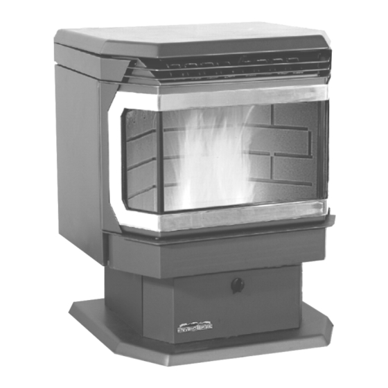
- Page 1 PELLET STOVE EF-IV i OWNERS TECHNICAL MANUAL SHERWOOD INDUSTRIES LTD. 6782 OLDFIELD RD VICTORIA, BRITISH COLUMBIA V8M-2A3...
-
Page 2: Table Of Contents
ENVIROFIRE INSTALLATION MANUAL TABLE OF CONTENTS 1) INTRODUCTION PAGE Important Safety Data............3 Pellet Quality ................ 4 Warnings and Recommendations......... 5 Automatic Safety Features ........... 5 2) OPERATION How to Start Your Pellet Appliance........6 Turning Your Pellet Appliance Off ........6 Slider/Damper............... -
Page 3: Important Safety Data
IMPORTANT SAFETY DATA To prevent the possibility of a fire, ensure that the appliance is properly installed by adhering to the installation instructions. An ENVIROFIRE dealer will be happy to assist you in obtaining information with regards to your local building codes and installation restrictions. The stove’s exhaust system works with negative combustion chamber pressure and a slightly positive chimney pressure, it is very important to ensure that the exhaust system be sealed and airtight. -
Page 4: Pellet Quality
PELLET QUALITY IS IMPORTANT, PLEASE READ THE FOLLOWING PAGE Your pellet stove has been designed to burn wood pellets only. Since there are many manufacturers of wood pellets it is important to select pellets that are free of dirt or any impurities. The Pellet Fuel Industries (P.F.I.) has established standards for wood pellet manufactures. -
Page 5: Warnings And Recommendations
WARNINGS AND RECOMMENDATIONS Do not abuse the glass by striking or slamming the door shut. Do not attempt to operate the stove with broken glass. Do not attempt to open the door and clean the glass while the unit is in operation. To clean the glass, use a soft cotton cloth and mild window cleaner, gas or wood stove glass cleaner or take a damp paper towel and dip into the fly ash, this is a very mild abrasive and will not damage the glass. -
Page 6: How To Start Your Pellet Appliance
HOW TO START AND OPERATE YOUR PELLET APPLIANCE Check and fill hopper with pellets. Make sure unit is plugged into a Convection working outlet. Blower Speed Control Switch the power “ON” by pushing the KNOB A start up switch once only. Turn knob “B”... -
Page 7: Slider/Damper
SLIDER/DAMPER INSTALLATION INSTRUCTIONS This is used to regulate the airflow through the pellet stove. A Qualified Service Technician or Installer should set the Slider Damper. The Slider Damper is pre set from the factory. The slider damper will be set and held in place with a 5/16” hex head screw. -
Page 8: Areas For Routine Maintenance
AREAS FOR ROUTINE INSPECTION The following should be inspected periodically to ensure that the appliance is operating at its optimum and giving you excellent heat value: 2 3 DAYS/WEEKLY SEASON or 2 TONS OF FUEL Burn Pot and Liner Exhaust Vent Ash Pan Fresh air Intake Tube Inside Firebox... - Page 9 have different ash contents. Ash content is a good indication of fuel efficiency and quality. Refer to “Warnings and Recommendations” for disposal of ashes. BLOWER MECHANISMS ( # 2 SEE PAGE 10) Unplug the stove then open the right/left side panels to access the two blowers. Only the convection blower motor (on the right side of the stove) will require lubrication.
-
Page 10: Electrical Component Functions
Once you are finished using the pellet appliance for the season, unplug the stove for added electrical protection. It is very important that the stove be cleaned and serviced as stated above. (See Section Areas of Routine Inspection) ELECTRICAL COMPONENT FUNCTIONS The following is a list of electrical components and their functions on the ENVIROFIRE EF-IVi pellet stove. - Page 11 EXHAUST/COMBUSTION BLOWER This variable speed fan (mounted on the left side of the stove) is responsible for drawing the outside fresh air into the combustion chamber for burning. The hot air then continues to be drawn over the heat exchanger tubes and into the exhaust channel.
- Page 12 160°F (71°C) TEMPERATURE SENSOR When this sensor (located on the left side firewall) reaches 160°F (71°C), the convection blower will go to high, bypassing the fan controller and removing excess heat from the unit. 120°F (49°C) N/O TEMPERATURE SENSOR (SHUT-DOWN SENSOR) This sensor (mounted on the exhaust blower housing) has two functions: Should the fire go out, this sensor will shut the stove off when the exhaust temperature drops below 120°F (49°C).
-
Page 13: Vent Termination Requirements
DECIDING WHERE TO LOCATE YOUR PELLET APPLIANCE Check clearances to combustibles. Do not obtain combustion air from an attic, garage or any unventilated space. Combustion air may be obtained from a ventilated crawlspace. Do not install the stove in a bedroom. You can vent the stove through an exterior wall behind the unit or connect it to an existing masonry or metal chimney (must be lined if the chimney is over 6”... -
Page 14: Removing Your New Stove From It's Pallet
REMOVING YOUR NEW STOVE FROM IT’S PALLET To remove your new stove from its pallet, open the left and right side panels. There are two wood screws that are holding the bottom of the stove to the pallet. Remove the screws. Close the side panels. See PAGE 18 how to install the pedestal. -
Page 15: Masonry Fireplace Insert Installation
MASONRY FIREPLACE INSERT INSTALLATION, MODEL FPI The Fireplace Insert model includes surround face. (Surround assembly instructions are in this manual). (SEE PAGE 15 in this manual) CLEARANCE TO COMBUSTIBLES: Side wall..........9” (200 mm) from the body of the heater Facing on masonry fireplace....9” (200 mm) from the body of the heater Mantle............8”... -
Page 16: Assembling The Face Plate For The Fpi Models
ASSEMBLING THE FACE PLATE FOR THE FPI MODEL To assemble the surround panels, lay the panels face down on a soft flat surface and align the outer edges of the sides with the top panel. Bolt the sides to the top using the hardware provided. (4 x 1/4” nuts and bolts) Assemble the brass frame using the corner hardware and screws supplied in the face plate packaging. -
Page 17: Model Fs (Freestanding) Installation
FREESTANDING INSTALLATION, MODEL FS CLEARANCE TO COMBUSTIBLES This unit must be installed on a noncombustible hearth pad, extending at least 6” (inches) (150 mm) in front of the appliance and at least the entire width of the appliance. -Side wall to unit A- 6 INCHES (150 mm) -Back wall to unit B- 2 INCH... -
Page 18: Pedestal Installation
-Side wall to unit ....E 6 INCHES (152 mm) -Mantle to unit F 10 INCHES (254 mm) -Top facing to unit G 8 INCHES (203 mm) -Side facing to unit H 9 INCHES (228 mm) -Floor protection D 6 INCHES (152 mm) FREESTANDING PEDESTAL INSTALLATION ASSEMBLY: Model FS comes with a pedestal that has to be attached prior to... -
Page 19: Horizontal Exhaust Through The Wall
HORIZONTAL EXHAUST THROUGH THE WALL Choose a location for your stove that meets the requirements stated in this manual and allows installation with the least amount of interference to house framing, plumbing, wiring, etc. Install a non-combustible hearth pad (where necessary). Place the appliance 15”... - Page 20 THROUGH WALL INSTALLATION...
-
Page 21: Inside Vertical Pipe Installation
INSIDE VERTICAL THROUGH THE ROOF INSTALLATION, Choose a stove location that is ideal. See the section Deciding Where to Locate Your Pellet Appliance. Place a non-combustible hearth pad where necessary. Place the unit on the hearth pad and space it in a manner so when the pellet vent is installed vertically, it will be 3”... -
Page 22: Outside Vertical Pipe Installation
OUTSIDE VERTICAL PIPE INSTALLATION To accomplish the above titled installation, follow steps 1 through 8 in the previous section and then finish it by performing the following. Install a tee with clean out on the outside of the house. Install PL vent upward from the tee. Make sure that you install support brackets to keep the vent straight and secure. -
Page 23: Mobile Home Installation
MOBILE HOME INSTALLATION Secure the heater to the floor using the two holes in the pedestal. Do not disturb the structural integrity of the home. Ensure the unit is electrically grounded to the chassis of your home (permanently). Do not install in a room people sleep in. Outside fresh air is mandatory. -
Page 24: Troubleshooting
TROUBLESHOOTING: DO NOT: Hold the start-up switch down, this is a momentary contact switch and can be damaged if held down too long. Service the stove with wet hands. The stove is an electrical appliance, which may pose a shock hazard if handled improperly. Only qualified technicians should deal with possible internal electrical failures. - Page 25 The stove will not operate when hot Unplug the stove, open the left side panel. Jump the two brown leads that are attached to the 120°F (49°C) Exhaust temperature sensor. If the stove operates replace the 120°F (49°C) sensor. The exhaust motor will not function normally Open the left side panel, check all connections against the wiring diagram.
- Page 26 The auger motor will not function normally Make sure the exhaust blower is operating. Make sure the dial-a-fire is turned on. Unplug the stove and open the side and back panels. Check all the connections to the auger motor, auger dial-a-fire, vacuum sensor, 200°F (93°C) temperature sensor and the timing control module against the wiring diagram in this manual.
- Page 27 The stove will not shut down Check the connections to the 120°F (49°C) exhaust temperature sensor, start-up switch and the start-up timer against the wiring diagram. Check the 120°F (49°C) temperature sensor by removing one of the brown wires from the sensor.
-
Page 28: Wiring Diagram
WIRING DIAGRAM... -
Page 29: Parts List
PARTS LIST EF4i-001 AUGER MOTOR EF4i-100 RETROFIT SLIDER KIT EF4i-002 CONVECTION BLOWER EF4i-103 ASH SILL EF4i-007 COMBUSTION BLOWER EF4i-104 HOPPER LID EF4i-008 COMBUSTION MAIN IMPELLER EF4i-104A FPI HOPPER LID EF4i-009 COMBUSTION COOLING IMPELLER EF4i-105 ASH PAN LATCH FS ONLY EF4i-010 EXHAUST TEMP SENSOR 120°F EF4i-111 FS STOVE TOP... -
Page 30: Exploded Views
AUGER BRASS BUSHINGS SET AUGER COMBUSTION of TWO BLOWER EF4i-025 FAN TEMP EXHAUST EF4i-065 EF4i-007 SENSOR TEMP SENSOR 16° F (71° C) 120° F (49° C) EF4i-013 EF4i-010 PIN IGNITER EF4i-127 HIGH LIMIT TEMP SENSOR 200° F (93° C) EF4i-016 VACUUM CONTROL PANEL SWITCH... - Page 31 STOVE TOP FS RIGHT FS STOVE TOP HANDLE CABINET EF4I-111 SIDE EF4i-143 STAINLESS BURN POT CONTROL LINER FIREBOX PANEL w BACK GRILL LINER TOP EF4i-024 DECAL EF4i-097 BAFFLE EF4i-053 EF4i-066 IGNITION BURN POT EF4i-021 VACUUM FIREBOX PORT LINER W/ COVER INSULATION EF4i-047 FRONT...
-
Page 32: Warranty
WARRANTY Sherwood Industries Ltd. gives a five year limited warranty on all steel manufactured parts. A one-year warranty is provided on all electrical components. The above limited warranties are extended only to the original purchaser. There is no warranty on the following parts: fiberglass rope baskets refractory material burn pot liner...
Need help?
Do you have a question about the EF-IV I and is the answer not in the manual?
Questions and answers