Table of Contents
Advertisement
Quick Links
Advertisement
Table of Contents

Related Manuals for RuggedCom RuggedSwitchi800


Summary of Contents for RuggedCom RuggedSwitchi800
-
Page 1: Installation Guide
RuggedSwitch™ i800 Family Installation Guide www.ruggedcom.com... - Page 2 We have checked the contents of this manual against the hardware and software described. However, deviations from the description cannot be completely ruled out. RuggedCom shall not be liable for any errors or omissions contained herein or for consequential damages in connection with the furnishing, performance, or use of this material.
-
Page 3: Federal Communications Commission Radio Frequency Interference Statement
Federal Communications Commission Radio Frequency Interference Statement This equipment has been tested and found to comply with the limits for a Class A digital device pursuant to Part 15 of the FCC Rules. These limits are designed to provide reasonable protection against harmful interference when the equipment is operated in a commercial environment. -
Page 4: Table Of Contents
Figure 5: DC Power supply and ground connections............11 Figure 6: Power Supply Wiring Examples............... 12 Figure 7: Failsafe Output Relay ..................13 Figure 8: RS232 Female DCE pin-out ................14 Figure 9: RJ45 Ethernet port pin-out................15 Figure 10: Mechanical Specifications................20 RuggedCom® RuggedSwitch™i800 family... -
Page 5: Product Overview
Note that despite the i800 family’s specifications, this product is not intended for mission critical power substation applications. For equipment designed for these environments, please visit http://www.ruggedcom.com or contact a Ruggedcom sales representative. 1.2 Feature Highlights • Integrated ROS™ management (optional):... -
Page 6: I800 Family Front Panel View
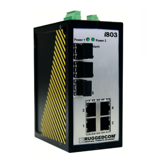
10/100 BaseTx RS-232 Console Port Memory Slot Figure 1: Front Panel The front panel shown is representative of the i800 family. Note that there are several Ethernet options available in several models, outlined in Section 1.3.2, below. RuggedCom® RuggedSwitch™i800 family... -
Page 7: Front Panel Leds
1000SX MM Not present 1000LX SM 10/100/1000Tx Not present 1000SX MM Not present Not present 1000LX SM Table 2: Front Panel Ethernet Options by model For detailed Ethernet port specifications, please refer to Sections 3.5 and 3.6. RuggedSwitch™i800 family RuggedCom®... -
Page 8: I800 Family Top Panel View
Fail-Safe Connector Relay Chassis Ratings: Ground 12-24V , , 2A front Figure 2: Top Panel For details on connecting the power supplies and Ground, see Section 2.2. For details on connecting the Fail-Safe Relay, see Section 2.3 RuggedCom® RuggedSwitch™i800 family... -
Page 9: I800 Family Bottom Panel View
Memory Slot SLOT RS-232 Console Port CONSOLE 57600-N-8-1 DIN Rail mounting back bracket Figure 3: Bottom Panel For details on connecting the console port, see Section 2.4. For a description of the memory slot, see Section 2.6. RuggedSwitch™i800 family RuggedCom®... -
Page 10: Installation
The i800 family of switches comes with a standard DIN rail mounting bracket. Figure 4 details the mounting configuration for a standard 1” DIN Rail. DIN Rail i802 Power 1 Power 2 Alarm DIN Rail mounting bracket Release direction Figure 4: DIN Rail Mounting RuggedCom® RuggedSwitch™i800 family... -
Page 11: Power Supply Wiring And Grounding
DC Power Supply 2 negative terminal Phoenix connector DC Power Supply 2 positive terminal Phoenix connector Chassis Chassis Ground connection Screw terminal on chassis Ground Table 3: Power Supply Connector Pinout NOTE: Terminals P1-, P2-, and GND are connected together internally. RuggedSwitch™i800 family RuggedCom®... -
Page 12: Figure 6: Power Supply Wiring Examples
The internal connection between P1-. P2-, and GND means that if two power supplies are connected to the unit, their negative terminals must be at the same potential. • Equipment must be installed according to the applicable country wiring codes. RuggedCom® RuggedSwitch™i800 family... -
Page 13: Failsafe Output Wiring
Common Figure 7: Failsafe Output Relay Function Normally closed (no power or critical Normally Closed alarm condition) Common Common relay contact Normally open (no power or critical Normally Open alarm condition) Table 4: Failsafe Output Relay Pinout RuggedSwitch™i800 family RuggedCom®... -
Page 14: Rs232 Console Port Wiring
DB9-Female to RJ45 console cable with the pin-outs listed in Table 5. Pin 8 Pin 1 Figure 8: RS232 Female DCE pin-out RuggedCom RS232 over RJ45 pin-out specification Signal Name (PC is DTE) DB9- Female RJ45 Male DCD –... -
Page 15: Rj45 Ports - Signal Description
The unused pins, 4, 5, 7, and 8 are terminated to Chassis Ground via a network that improves EMI and ESD performance. RuggedCom does not recommend the use of copper cabling of any length for critical real-time substation automation applications. However, transient suppression circuitry is present on all copper ports to protect against damage from electrical transients. -
Page 16: Memory Slot
Ensure that power is not applied to the unit when removing or inserting the memory module. NOTE: These features are pending and are not currently supported. The memory card shipped with the unit will support these features as they become available. Please contact RuggedCom for details. RuggedCom® RuggedSwitch™i800 family... -
Page 17: Technical Specifications
Humidity (Damp 95% (non-condensing), 55°C , 6 IEC 60068-2-30 Test Db Heat, Cyclic) cycles IEC 60255-21-1 Vibration Tests Fc 1g @ (10 - 500) Hz IEC 60255-21-2 Shock Tests Ea 30g @ 11mS Table 8: Environmental Type Tests RuggedSwitch™i800 family RuggedCom®... -
Page 18: Environmental Specifications
1A @ 30VDC, 0.3A @ 80VDC Table 11: Failsafe Relay Specification NOTES: • Resistive Load. • For Class-2 circuits only. Isolation Comments 1500 V Dielectric test voltage (1 minute) between coil & contacts Table 12: Failsafe Relay Isolation RuggedCom® RuggedSwitch™i800 family... -
Page 19: Rj45 Ethernet Port Specifications
To convert from average to peak add 3 dBm. To convert from peak to average, subtract 3 dBm. • Maximum segment length is greatly dependent on factors such as fiber quality, and number of patches and splices. Please consult RuggedCom sales associates when determining maximum segment distances. RuggedSwitch™i800 family RuggedCom®... -
Page 20: Physical Dimensions
Figure 10: Mechanical Specifications Parameter Value Comments 4.625 x 2.25 x 3.75 inches Dimensions (height x width x depth) (117 x 57 x 95 mm) Weight 1.5 lb (0.68 Kg) Enclosure Die cast Aluminum Table 16: Physical Dimensions RuggedCom® RuggedSwitch™i800 family... -
Page 21: Agency Approvals
(i) product performance is not guaranteed; (ii) the manufacturers warranty will not be applicable (i.e. it will be voided and technical support will not be provided) and (iii) RuggedCom will not accept any liabilities as a result of performance issues.
Need help?
Do you have a question about the RuggedSwitchi800 and is the answer not in the manual?
Questions and answers