
Subscribe to Our Youtube Channel
Related Manuals for LevelOne GSW-1676


Summary of Contents for LevelOne GSW-1676
-
Page 1: User Manual
LevelOne GSW-1676 16-Port Gigabit w/ 4-Port SFP Web Smart Switch User Manual Version 1.0-0612... - Page 3 OMPLIANCES FCC - Class A This equipment has been tested and found to comply with the limits for a Class A digital device, pursuant to part 15 of the FCC Rules. These limits are designed to provide reasonable protection against harmful interference when the equipment is operated in a commercial environment.
- Page 4 OMPLIANCES CE Mark Declaration of Conformance for EMI and Safety (EEC) This information technology equipment complies with the requirements of the Council Directive 89/336/EEC on the Approximation of the laws of the Member States relating to Electromagnetic Compatibility and 73/23/EEC for electrical equipment used within certain voltage limits and the Amendment Directive 93/68/EEC.
-
Page 5: Safety Compliance
OMPLIANCES Safety Compliance Warning: Fiber Optic Port Safety When using a fiber optic port, never look at the transmit laser while CLASS I it is powered on. Also, never look directly at the fiber TX port and LASER DEVICE fiber cable ends when they are powered on. Avertissment: Ports pour fibres optiques - sécurité... - Page 6 OMPLIANCES Important! Before making connections, make sure you have the correct cord set. Check it (read the label on the cable) against the following: Power Cord Set U.S.A. and Canada The cord set must be UL-approved and CSA certified. The minimum specifications for the flexible cord are: - No.
-
Page 7: Warnings And Cautionary Messages
OMPLIANCES Warnings and Cautionary Messages Warning: This product does not contain any serviceable user parts. Warning: Installation and removal of the unit must be carried out by qualified personnel only. Warning: When connecting this device to a power outlet, connect the field ground lead on the tri-pole power plug to a valid earth ground line to prevent electrical hazards. -
Page 8: Related Publications
OMPLIANCES This guide details the hardware features of this switch, including Its physical and performance-related characteristics, and how to install the switch. Audience This guide is for system administrators with a working knowledge of network management. You should be familiar with switching and networking concepts. Related Publications As part of the switch firmware, there is an online web-based help that describes all management related features. -
Page 9: Table Of Contents
ONTENTS About GSW-1676 1-1 Overview ..........1-1 Switch Architecture . - Page 10 ABLE OF ONTENTS Desktop or Shelf Mounting ......3-6 Installing an SFP Transceiver ....... . . 3-7 Connecting to a Power Source .
- Page 11 ABLE OF ONTENTS Configuring Rate Limits ....... 5-22 Storm Control ........5-24 Port Mirroring .
- Page 12 ABLE OF ONTENTS Management Features ........C-2 Standards .
- Page 13 ABLES Table 1-1 Port Status LEDs ........1-4 Table 1-2 Power Status LED .
- Page 14 IGURES Figure 1-1 Front Panel ........1-1 Figure 1-2 Rear Panel .
- Page 15 IGURES Figure 5-20 Trunk Membership ......5-28 Figure 5-21 Trunk Configuration ......5-29 Figure 5-22 Trunk Rate Limiting .
- Page 16 IGURES...
-
Page 17: Overview
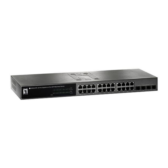
HAPTER GSW-1676 BOUT Overview LevelOne GSW-1676 is an intelligent Layer 2 switch with 16 10/100/ 1000BASE-T ports, four of which are combination ports that are shared with four SFP transceiver slots (see Figure 1-1, Ports 13-16). Port Status Indicators 10/100/1000 Mbps RJ-45 Ports... -
Page 18: Switch Architecture
GSW-1676 BOUT Switch Architecture The switch employs a wire-speed, non-blocking switching fabric. This permits simultaneous wire-speed transport of multiple packets at low latency on all ports. The switch also features full-duplex capability on all ports, which effectively doubles the bandwidth of each connection. -
Page 19: Description Of Hardware
ESCRIPTION OF ARDWARE Description of Hardware 10/100/1000BASE-T Ports The switch contains 16 RJ-45 ports that operate at 10 Mbps or 100 Mbps, half or full duplex, or at 1000 Mbps, full duplex. Because all ports on the switch support automatic MDI/MDI-X operation, you can use straight-through cables for all network connections to PCs or servers, or to other switches or hubs. -
Page 20: Table 1-1 Port Status Leds
GSW-1676 BOUT ort SFP Web Smart Switch 1000 M Link/Act 1000 M 10 11 13 14 15 16 Link/Act Power Power Status LED Port Status LEDs Figure 1-3 Port LEDs and Power LED Table 1-1 Port Status LEDs Condition Status... -
Page 21: Power Supply Socket
EATURES AND ENEFITS Power Supply Socket The power socket is located on the rear panel of the switch. The standard power socket is for the AC power cord. 100-240V 50-60Hz 0.8A Figure 1-4 Power Supply Socket Features and Benefits Connectivity •... -
Page 22: Expandability
GSW-1676 BOUT Expandability • 4 Small Form Factor Pluggable (SFP) transceiver slots (shared with 1000BASE-T ports) • Supports 1000BASE-SX, 1000BASE-LX and 1000BASE-ZX SFP transceivers. Performance • Transparent bridging. • Provides store-and-forward switching • Supports Jumbo frames up to 9.6 Kbytes •... -
Page 23: Network Planning
HAPTER ETWORK LANNING Introduction to Switching A network switch allows simultaneous transmission of multiple packets via non-crossbar switching. This means that it can partition a network more efficiently than bridges or routers. Switches have, therefore, been recognized as one of the most important building blocks for today’s networking technology. -
Page 24: Application Examples
ETWORK LANNING Application Examples GSW-1676 is not only designed to segment your network, but also to provide a wide range of options in setting up network connections. Some typical applications are described below. Collapsed Backbone GSW-1676 is an excellent choice for mixed Ethernet, Fast Ethernet, and Gigabit Ethernet installations where significant growth is expected in the near future. -
Page 25: Central Wiring Closet
1 Gbps full-duplex connections for up to 16 local segments. In addition, the switch is also connecting remote servers over fiber optic cable at 1 Gbps. 10/100/1000 Switch level GSW-1676 16 Port Gigabit w 4 Port SFP Web Smart Switch 1000 M Shared SFP Port Link/Act o n e... -
Page 26: Remote Connections With Fiber Cable
70 kilometers away. The figure below illustrates three GSW-1676 switches stack interconnecting multiple segments with fiber cable. Headquarters level GSW-1676 16 Port Gigabit w 4 Port SFP Web Smart Switch 1000 M Shared SFP Port Link/Act o n e... -
Page 27: Making Vlan Connections
VLANs should be used for larger networks, and all the VLANs assigned to the inter-switch links. R&D VLAN 1 level GSW-1676 16 Port Gigabit w 4 Port SFP Web Smart Switch 1000 M Shared SFP Port Link/Act o n e... -
Page 28: Application Notes
ETWORK LANNING Application Notes 1. Full-duplex operation only applies to point-to-point access (such as when a switch is attached to a workstation, server or another switch). When the switch is connected to a hub, both devices must operate in half-duplex mode. 2. -
Page 29: Installing The Switch
HAPTER NSTALLING THE WITCH Selecting a Site GSW-1676 can be mounted in a standard 19-inch equipment rack or on a flat surface. Be sure to follow the guidelines below when choosing a location. • The site should: - be at the center of all the devices you want to link and near a power outlet. -
Page 30: Ethernet Cabling
NSTALLING THE WITCH Ethernet Cabling To ensure proper operation when installing the switches into a network, make sure that the current cables are suitable for 10BASE-T, 100BASE-TX or 1000BASE-T operation. Check the following criteria against the current installation of your network: •... -
Page 31: Equipment Checklist
• A screwdriver Mounting GSW-1676 can be mounted in a standard 19-inch equipment rack or on a desktop or shelf. Mounting instructions for each type of site follow. Rack Mounting Before rack mounting the switch, pay particular attention to the following... - Page 32 NSTALLING THE WITCH • Temperature: Since the temperature within a rack assembly may be higher than the ambient room temperature, check that the rack-environment temperature is within the specified operating temperature range (see page C-2). • Mechanical Loading: Do not place any equipment on top of a rack-mounted unit.
-
Page 33: Figure 3-2 Attaching The Brackets
OUNTING To rack-mount devices: 1. Attach the brackets to the device using the screws provided in the Bracket Mounting Kit. S h a r e d S F P P o r t Figure 3-2 Attaching the Brackets 2. Mount the device in the rack, using four rack-mounting screws (not provided). -
Page 34: Desktop Or Shelf Mounting
NSTALLING THE WITCH 3. If installing a single switch only, turn to “Connecting to a Power Source” at the end of this chapter. 4. If installing multiple switches, mount them in the rack, one below the other, in any order. Desktop or Shelf Mounting 1. -
Page 35: Installing An Sfp Transceiver
SFP T NSTALLING AN RANSCEIVER Installing an SFP Transceiver S h a r e d S F P P o r t Figure 3-5 Inserting an SFP Transceiver into a Slot The switch supports the following optional transceivers: • 1000BASE-SX (GVT-0300) •... -
Page 36: Connecting To A Power Source
NSTALLING THE WITCH Connecting to a Power Source To connect a device to a power source: 1. Insert the power cable plug directly into the socket located at the back of the device. 100-240V 50-60Hz 0.8A Figure 3-6 Power Socket 2. -
Page 37: Making Network Connections
ONNECTIONS Connecting Network Devices GSW-1676 is designed to interconnect multiple segments (or collision domains). It can be connected to network cards in PCs and servers, as well as to hubs, switches or routers. It may also be connected to devices using optional SFP transceivers. -
Page 38: Connecting To Pcs, Servers, Hubs And Switches
AKING ETWORK ONNECTIONS Connecting to PCs, Servers, Hubs and Switches 1. Attach one end of a twisted-pair cable segment to the device’s RJ-45 connector. Figure 4-1 Making Twisted-Pair Connections 2. If the device is a PC card and the switch is in the wiring closet, attach the other end of the cable segment to a modular wall outlet that is connected to the wiring closet. -
Page 39: Network Wiring Connections
Labeling and Connection Records” on page 4-8. Equipment Rack (side view) Network Switch level GSW-1676 16 Port Gigabit w 4 Port SFP Web Smart Switch w it ch 10 /1 0 0 1000 M 6 7 2 4 L 3 Shared SFP Port... -
Page 40: Fiber Optic Sfp Devices
AKING ETWORK ONNECTIONS Fiber Optic SFP Devices An optional Gigabit SFP transceiver (1000BASE-SX, 1000BASE-LX or 1000BASE-ZX) can be used for a backbone connection between switches, or for connecting to a high-speed server. Each single-mode fiber port requires 9/125 micron single-mode fiber optic cable with an LC connector at both ends. -
Page 41: Figure 4-3 Making Connections To Sfp Transceivers
SFP D IBER PTIC EVICES 3. Connect one end of the cable to the LC port on the SFP module and the other end to the LC port on the other device. Since LC connectors are keyed, the cable can be attached in only one orientation. S h a r e d S F P... -
Page 42: Connectivity Rules
AKING ETWORK ONNECTIONS Connectivity Rules When adding hubs (repeaters) to your network, please follow the connectivity rules listed in the manuals for these products. However, note that because switches break up the path for connected devices into separate collision domains, you should not include the switch or connected cabling in your calculations for cascade length involving other devices. -
Page 43: 100 Mbps Fast Ethernet Collision Domain
ONNECTIVITY ULES Table 4-3 Maximum 1000BASE-LX Fiber Optic Cable Length Fiber Diameter Fiber Cable Length Connector Bandwidth Range 9/125 micron 2 m - 10km single-mode fiber (7 ft - 6.4 miles) Table 4-4 Maximum 1000BASE-ZX Fiber Optic Cable Length Fiber Diameter Fiber Cable Length Connector... -
Page 44: Cable Labeling And Connection Records
AKING ETWORK ONNECTIONS Cable Labeling and Connection Records When planning a network installation, it is essential to label the opposing ends of cables and to record where each cable is connected. Doing so will enable you to easily locate inter-connected devices, isolate faults and change your topology without need for unnecessary time consumption. -
Page 45: Configuring The Switch
HAPTER ONFIGURING THE WITCH Using the Web Interface This switch provides an embedded HTTP web agent. Using a web browser you can configure the switch and view statistics to monitor network activity. The web agent can be accessed by any computer on the network using a standard web browser (Internet Explorer 5.5 or above, or Mozilla Firefox 1.0 or above). -
Page 46: Navigating The Web Browser Interface
ONFIGURING THE WITCH Navigating the Web Browser Interface To access the web-browser interface you must first enter a password. The user has read/write access to all configuration parameters and statistics. The default password for the switch is “admin.” Note: If user input is not detected within five minutes, the current session is terminated. -
Page 47: Configuration Options
AVIGATING THE ROWSER NTERFACE Configuration Options Configurable parameters have a dialog box or a drop-down list. Once a configuration change has been made on a page, be sure to click on the Apply button to confirm the new setting. The following table summarizes the web page configuration buttons. -
Page 48: Main Menu
ONFIGURING THE WITCH Main Menu Using the onboard web agent, you can define system parameters, manage and control the switch, and all its ports, or monitor network conditions. The following table briefly describes the selections available from the web-browser interface. Table 5-2 Switch Main Menu Menu Description... - Page 49 AVIGATING THE ROWSER NTERFACE Table 5-2 Switch Main Menu (Continued) Menu Description Page PORTS 5-21 Settings Configure the speed and duplex mode of the 5-21 port. Rate Limiting Sets the rate limiting parameters for ports. 5-22 Storm Control Sets the broadcast storm control parameters. 5-24 Port Mirroring Sets up the port mirroring features of the...
-
Page 50: Web Configuration
ONFIGURING THE WITCH Web Configuration Displaying Status Overview You can easily identify the system by displaying the device name, location and contact information. Field Attributes System Information • System Name – Name assigned to the switch system. • Number of Ports – Number of built-in ports. •... - Page 51 ONFIGURATION • Speed/Duplex Status – Shows the current speed and duplex mode. • 10hdx: 10 Mbps half duplex. • 10fdx: 10 Mbps full duplex. • 100hdx: 100 Mbps half duplex. • 100fdx: 100 Mbps full duplex. • 1000fdx: 1000 Mbps full duplex. •...
-
Page 52: Figure 5-3 Switch Information
ONFIGURING THE WITCH Web – Click STATUS, Overview. Figure 5-3 Switch Information... -
Page 53: Showing Port Statistics
ONFIGURATION Showing Port Statistics You can display statistics on network traffic from the ports. These statistics can be used to identify potential problems with the switch (such as a faulty port or unusually heavy loading). All values displayed have been accumulated since the last system reboot, but can be reset to zero by clicking the CLEAR button. - Page 54 ONFIGURING THE WITCH Table 5-3 Port Statistics (Continued) Parameter Description Received Multicast Packets The number of packets, delivered by this sub-layer to a higher (sub-)layer, which were addressed to a multicast address at this sub-layer. Received Broadcast The number of packets, delivered by this sub-layer to Packets a higher (sub-)layer, which were addressed to a broadcast address at this sub-layer.
- Page 55 ONFIGURATION Table 5-3 Port Statistics (Continued) Parameter Description Undersize Frames The total number of frames received that were less than 64 octets long (excluding framing bits, but including FCS octets) and were otherwise well formed. Fragments The total number of frames received that were less than 64 octets in length (excluding framing bits, but including FCS octets) and had either an FCS or alignment error.
- Page 56 ONFIGURING THE WITCH Table 5-3 Port Statistics (Continued) Parameter Description 64 Bytes Frames The total number of frames (including bad packets) received and transmitted that were 64 octets in length (excluding framing bits but including FCS octets). 65-127 Byte Frames The total number of frames (including bad packets) received and transmitted where the number of octets 128-255 Byte Frames...
-
Page 57: Displaying System Name
ONFIGURATION Web – Click STATUS, Statistics. Figure 5-4 Port Statistics Displaying System Name You can easily identify the system by displaying the device name. Field Attributes • Switch Name – Name assigned to the switch system. 5-13... -
Page 58: Setting The Switch's Ip Address
ONFIGURING THE WITCH Web – Click System, Name. Figure 5-5 System Name Setting the Switch’s IP Address This section describes how to configure an IP interface for management access over the network. The IP address for this switch is 192.168.2.10 by default. -
Page 59: Configuring The Logon Password
ONFIGURATION Manual Configuration Web – Click System, LAN Settings. Enter the IP address, subnet mask and gateway, then click APPLY. Note that if you change the switch IP address, you must close the web interface and start a new session using the new IP address. -
Page 60: Tools
ONFIGURING THE WITCH Web – Click System, Password. To change the password for the administrator, enter current password, the new password, confirm it by entering it again, then click APPLY. Figure 5-7 Password Settings Tools On the Tools page, you can restore the switch to default settings, upgrade the firmware of the switch, or restart the switch. -
Page 61: Figure 5-8 Reset To Factory Defaults
ONFIGURATION Web – Click System, Tools, Reset to Factory Defaults. Figure 5-8 Reset to Factory Defaults Upgrade Firmware To Upgrade the switch system firmware, select “Upgrade Firmware” from the Tools drop-down list then click on the “Browse” button to select the firmware file. -
Page 62: Figure 5-10 Restart Switch
ONFIGURING THE WITCH Upload/Download Configuration Web – Click SYSTEM, Tools, Upload/Download Configuration. To upload or download the configuration file, select "Upload/Download Configuration" from the Tools drop-down list, then click "Upload" or "Download", and then click on the "Browse" button to select the file. Figure 5-10 Restart Switch Set boot Image Web –... -
Page 63: Static Mac
ONFIGURATION Restart Switch Web – Click SYSTEM, Tools, Restart Switch. To restart the switch, select from the Tools drop-down list, and then click APPLY. The reset will be complete when the user interface displays the login page. Figure 5-12 Restart Switch Static MAC Switches store the MAC addresses for all known devices in the attached network. -
Page 64: Counter Config
ONFIGURING THE WITCH Web – Click System, Static MAC. Enter the MAC address, VLAN ID, then click ADD button to add a new static MAC address. Figure 5-13 Static MAC Address Configuration Counter Config This page allows specific statistics to be selected for monitoring. It is possible to monitor up to five transmit counters and five receive counters, as well as 1 transmit byte counter and receive byte counter. -
Page 65: Port Configuration
ONFIGURATION Web – Click System, Counter Config Figure 5-14 Counter Configuration Port Configuration You can use the Port Configuration page to manually fix the speed, duplex mode, and flow control. Field Attributes • Enable Jumbo Frames– Click to enable or disable Jumbo Frames. •... -
Page 66: Configuring Rate Limits
ONFIGURING THE WITCH Web – Click PORTS, Settings. Figure 5-15 Port Configuration Configuring Rate Limits This function allows the network manager to control the maximum rate for traffic transmitted or received on an interface. Rate limiting is configured on interfaces at the edge of a network to limit traffic into or out of the switch. -
Page 67: Figure 5-16 Rate Limiting
ONFIGURATION The Input/Output Bandwidth Limit field is a type-in box which accepts an integer number in the range 1 to 100. The number specifies the percentage of the total bandwidth of the port that can be used before packets are dropped or flow-control starts. -
Page 68: Storm Control
ONFIGURING THE WITCH Storm Control Broadcast storms may occur when a device on your network is malfunctioning, or if application programs are not well designed or properly configured. If there is too much broadcast traffic on your network, performance can be severely degraded or everything can come to complete halt. -
Page 69: Port Mirroring
ONFIGURATION Web – Click PORTS, Storm Control. This page enables you to set the broadcast storm control parameters for every port on the switch. Figure 5-17 Port Broadcast Control Port Mirroring You can mirror traffic from any source port to a target port for real-time analysis. -
Page 70: Cable Diagnostic
ONFIGURING THE WITCH switch, which means they will not reach the mirror port or their intended destination port. Input rate-limiting in conjunction with port flow-control should be used to ensure that the total ingress bandwidth never exceeds the egress bandwidth. Web –... -
Page 71: Trunks Membership
ONFIGURATION • Cable Status – Shows the cable length, operating conditions and isolates a variety of common faults that can occur on Category 5 twisted pair cabling. Web – Click PORTS, Port Mirroring. Figure 5-19 Cable Diagnostics Trunks Membership This page allows you to create a maximum of eight trunks of up to eight ports each. -
Page 72: Trunk Configuration
ONFIGURING THE WITCH • Trunk T1-T8 – These columns correspond to the eight trunks that are supported by the switch. To assign a port to a trunk, click on the radio button in the corresponding column, then click APPLY. Web – Click TRUNKS, Membership. To assign a port to a trunk, click the required trunk number, then click APPLY. -
Page 73: Trunk Rate Limit
ONFIGURATION • Flow Control – Allows flow control to be enabled or disabled. When the box is checked, flow control is enabled. • Ports – Indicates which ports belong to the trunk. Web – Click TRUNKS, Settings. Figure 5-21 Trunk Configuration Trunk Rate Limit This page allows you to change the maximum input and output data rate for each each trunk on the switch. -
Page 74: Vlan Settings
ONFIGURING THE WITCH Web – Click TRUNKS, Settings. Figure 5-22 Trunk Rate Limiting VLAN Settings This page allows you to create and delete VLANs (Virtual LANs) and to change the VLAN membership and behaviour of individual ports. VLANs are powerful, but can be difficult to set up properly. Each row of the table corresponds to one port or trunk;... - Page 75 ONFIGURATION • The switch management interface is on VLAN 1 (this cannot be changed) • All ports have a Port VLAN ID (PVID) of 1 • All ports can send and receive both VLAN-tagged and untagged packets (that is, they are hybrid ports) In the default configuration, any port is able to send traffic to any other port and a PC connected to any port will be able to access the management interface.
- Page 76 ONFIGURING THE WITCH For QinQ operation, a customer port should be set to VLAN unaware and a provider port (trunk port) should be set to VLAN aware. • QinQ – A QinQ enabled port will accept packets up to 1526 bytes in length, which means double tag header frames can be accepted.
-
Page 77: Figure 5-23 Vlan Settings
ONFIGURATION Web – Click VLANS, VLAN Settings. Fill in the required settings for each interface, click Apply. Figure 5-23 VLAN Settings VLAN Memembership You can create up to 255 VLANs based on 802.1Q standard and delete VLANs (Virtual LANs) to change the VLAN membership and behaviour of individual ports. -
Page 78: Figure 5-24 802.1Q Vlan Configuration
ONFIGURING THE WITCH Web – Click VLANS, VLAN Membership. To add a new , type into the VLAN ID (1-4095) of the VLAN group you want the new group to be, then click Add to open up the 802.1Q VLAN Group window, on which you can configure VLAN membership. -
Page 79: Qos Settings
ONFIGURATION QOS Settings QoS (Quality of Service) is a mechanism that is used to prioritize certain traffic as it is forward through the switch. Traffic can be classified as High or Normal priority and, when the switch is heavily loaded, it is the Normal priority packets that are dropped first. -
Page 80: Security
ONFIGURING THE WITCH The Differentiated Services Code Point (DSCP) is a six-bit field that is contained within an IP (TCP or UDP) header. The six bits allow the DSCP field to take any value in the range 0 - 63 inclusive. When QoS Mode is set to DSCP, the DSCP Configuration table is displayed, which allows a priority (normal or high) to be set for each of the DSCP values. - Page 81 ONFIGURATION Field Attributes • Port - The front-panel port-number of the port. This cannot be changed. • Mode - Select the IP filter mode for this port. • Disabled - Disable the source IP filter. • Static - Enable the IP filter with configured values in the Address and IP Mask fields.
-
Page 82: Figure 5-27 Ip Filter Configuration
ONFIGURING THE WITCH Web – Click Security, IP Filter. Figure Figure 5-27 IP Filter Configuration Port Security Port security is a feature that allows you to configure a port with one or more MAC addresses that are authorized to access the network through that port. - Page 83 ONFIGURATION Field Attributes • Port - The front-panel port-number of the port. This cannot be changed. • Allowed number of Learned MAC addresses - Set the maximum of MAC addresses that can be learned by this port. The Mode settings for the port are set by a single drop-down list.
-
Page 84: Figure 5-28 Port Security
ONFIGURING THE WITCH • Trunk - Display the trunk ID if the port is member of a trunk group. Web – Click Security, Port Cecurity. Figure 5-28 Port Security This page enables you to set up a management access filter on the switch. With the Management Access Filter Configuration table, you can create a list of up to 8 IP addresses or IP address groups that are allowed management access to the switch through the web interface or SNMP. -
Page 85: Igmp Snoop
ONFIGURATION Web – Click Security, ACL. Figure 5-29 Management Access Filter Configuration IGMP Snoop The switch can use Internet Group Management Protocol (IGMP) to filter multicast traffic. IGMP Snooping monitors IGMP service requests passing between multicast clients and servers, and dynamically configures the ports which need to recieve the mulitcast traffic. - Page 86 ONFIGURING THE WITCH Settings Field Attributes IGMP Snooping Configuration • IGMP Enabled - When enabled, the switch will monitor network traffic to determine which hosts want to receive multicast traffic. • Router Ports - Set if ports are conneting to the IGMP administrative routers.
-
Page 87: Figure 5-30 Igmp Snooping Configuration
ONFIGURATION Web – Click IGMP Snoop, Settings. Figure 5-30 IGMP Snooping Configuration IGMP Status Show the IGMP Snooping statistics for the whole switch Field Attributes • VLAN ID - VLAN ID number. • Querier - Show whether Querying is enabled. •... -
Page 88: Figure 5-31 Igmp Snoop Status
ONFIGURING THE WITCH Web – Click IGMP Snoop, Status. Figure 5-31 IGMP Snoop Status 5-44... -
Page 89: Troubleshooting
PPENDIX ROUBLESHOOTING Diagnosing Switch Indicators Table A-1 Troubleshooting Chart Symptom Action Power LED is Off • Check connections between the switch, the power cord, and the wall outlet. • Contact your dealer for assistance. • Contact LevelOne Technical Support. Link LED is Off •... -
Page 90: Power And Cooling Problems
ROUBLESHOOTING Power and Cooling Problems If the power indicator does not turn on when the power cord is plugged in, you may have a problem with the power outlet, power cord, or internal power supply. However, if the unit powers off after running for a while, check for loose power connections, power losses or surges at the power outlet, and verify that the fans on the unit are unobstructed and running prior to shutdown. -
Page 91: Reset The Switch
ESET THE WITCH Reset the Switch As situation requires, you might want to reset the switch and to restore to the default settings. To reset the switch: 1. Unplug the power cord from the power socket. 2. Unplug all cables from the ports. 3. - Page 92 ROUBLESHOOTING...
-
Page 93: Cables
PPENDIX ABLES Twisted-Pair Cable and Pin Assignments For 10BASE-T/100BASE-TX connections, a twisted-pair cable must have two pairs of wires. For 1000BASE-T connections the twisted-pair cable must have four pairs of wires. Each wire pair is identified by two different colors. For example, one wire might be green and the other, green with white stripes. -
Page 94: 10Base-T/100Base-Tx Pin Assignments
ABLES 10BASE-T/100BASE-TX Pin Assignments Use unshielded twisted-pair (UTP) or shielded twisted-pair (STP) cable for RJ-45 connections: 100-ohm Category 3 or better cable for 10 Mbps connections, or 100-ohm Category 5 or better cable for 100 Mbps connections. Also be sure that the length of any twisted-pair connection does not exceed 100 meters (328 feet). -
Page 95: Straight-Through Wiring
WISTED ABLE AND SSIGNMENTS Straight-Through Wiring If the twisted-pair cable is to join two ports and only one of the ports has an internal crossover (MDI-X), the two pairs of wires must be straight-through. (When auto-negotiation is enabled for any RJ-45 port on the switch, you can use either straight-through or crossover cable to connect to any device type.) You must connect all four wire pairs as shown in the following diagram to... -
Page 96: Crossover Wiring
ABLES Crossover Wiring If the twisted-pair cable is to join two ports and either both ports are labeled with an “X” (indicating MDI-X) or neither port is labeled with an “X” (which indicates MDI), a crossover must be implemented in the wiring. -
Page 97: 1000Base-T Pin Assignments
WISTED ABLE AND SSIGNMENTS 1000BASE-T Pin Assignments All 1000BASE-T ports support automatic MDI/MDI-X operation, so you can use straight-through cables for all network connections to PCs or servers, or to other switches or hubs. The table below shows the 1000BASE-T MDI and MDI-X port pinouts. These ports require that all four pairs of wires be connected. -
Page 98: Adjusting Existing Category 5 Cabling To Run 1000Base-T
ABLES Note that when testing your cable installation, be sure to include all patch cables between switches and end devices. Adjusting Existing Category 5 Cabling to Run 1000BASE-T If your existing Category 5 installation does not meet one of the test parameters for 1000BASE-T, there are basically three measures that can be applied to try and correct the problem: 1. -
Page 99: Specifications
PPENDIX PECIFICATIONS Physical Characteristics Ports 12 10/100/1000BASE-T, with auto-negotiation 4 10/100/1000BASE-T shared with 4 SFP transceiver slots. Network Interface Ports 1-16: RJ-45 connector, auto MDI/X 10BASE-T: RJ-45 (100-ohm, UTP cable; Category 3 or better) 100BASE-TX: RJ-45 (100-ohm, UTP cable; Category 5 or better) 1000BASE-T: RJ-45 (100-ohm, UTP or STP cable;... -
Page 100: Switch Features
PECIFICATIONS Size 44.0 x 17.1 x 4.3 cm (17.0 x 6.7 x 1.7 in.) Temperature Operating: 0 to 40 °C (32 to 104 °F) Storage: -40 to 70 °C (-40 to 158 °F) Humidity Operating: 10% to 90% (non-condensing) AC Input 100 to 240 V, 50-60 Hz, 0.8 A Power Supply Internal, auto-ranging transformer: 100 to 240 VAC, 50 to 60 Hz... -
Page 101: Standards
TANDARDS Software Loading HTTP in-band Standards IEEE 802.3-2005 Ethernet, Fast Ethernet, Gigabit Ethernet IEEE 802.1Q Virtual LAN IEEE 802.1X, Port-Based Network Access Control, 2001 ISO/IEC 8802-3 Compliances CE Mark Emissions FCC Class A... - Page 102 PECIFICATIONS...
- Page 103 LOSSARY 10BASE-T IEEE 802.3 specification for 10 Mbps Ethernet over two pairs of Category 3 or better UTP cable. 100BASE-TX IEEE 802.3u specification for 100 Mbps Fast Ethernet over two pairs of Category 5 or better UTP cable. 1000BASE-LX IEEE 802.3z specification for Gigabit Ethernet over two strands of 50/125, 62.5/125 or 9/125 micron core fiber cable.
- Page 104 LOSSARY Bandwidth The difference between the highest and lowest frequencies available for network signals. Also synonymous with wire speed, the actual speed of the data transmission along the cable. Collision A condition in which packets transmitted over the cable interfere with each other.
-
Page 105: Full Duplex
LOSSARY Full Duplex Transmission method that allows two network devices to transmit and receive concurrently, effectively doubling the bandwidth of that link. Gigabit Ethernet A 1000 Mbps network communication system based on Ethernet and the CSMA/CD access method. IEEE Institute of Electrical and Electronic Engineers. IEEE 802.3 Defines carrier sense multiple access with collision detection (CSMA/CD) access method and physical layer specifications. -
Page 106: Network Diameter
LOSSARY Layer 2 Data Link layer in the ISO 7-Layer Data Communications Protocol. This is related directly to the hardware interface for network devices and passes on traffic based on MAC addresses. Light emitting diode used for monitoring a device or network condition. Link Segment Length of twisted-pair or fiber cable joining a pair of repeaters or a repeater and a PC. - Page 107 LOSSARY Redundant Power Supply (RPS) A backup power supply unit that automatically takes over in case the primary power supply should fail. RJ-45 Connector A connector for twisted-pair wiring. Switched Ports Ports that are on separate collision domains or LAN segments. Telecommunications Industry Association Transmission Control Protocol/Internet Protocol (TCP/IP) Protocol suite that includes TCP as the primary transport protocol, and IP...
- Page 108 LOSSARY Glossary-6...
- Page 109 NDEX Numerics compliances EMC C-3 10 Mbps connectivity rules 4-7 connectivity rules 100 Mbps connectivity rules 4-7 10 Mbps 4-7 1000 Mbps connectivity rules 4-6 100 Mbps 4-7 1000BASE-LX fiber cable lengths 4-7 1000 Mbps 4-6 1000BASE-SX fiber cable lengths 4-6 contents of package 3-3 1000BASE-T cooling problems A-2...
- Page 110 NDEX installation connecting devices to the switch 4-2 desktop or shelf mounting 3-6 package contents 3-3 port connections 4-1 passwords power requirements 3-1 administrator setting 5-15 problems A-2 pin assignments B-1 rack mounting 3-3 1000BASE-T B-5 site requirements 3-1 100BASE-TX/10BASE-T B-2 wiring closet connections 4-7 port, statistics 5-9 IP address...
- Page 111 NDEX switch architecture 1-2 switching, introduction to 2-1 VLANs tagging 2-5 temperature within a rack 3-4 troubleshooting in-band access A-2 Web interface power and cooling problems A-2 access requirements 5-1 switch indicators A-1 configuration buttons 5-3 twisted-pair connections 4-1 home page 5-2 menu list 5-4 panel display 5-3 user password 5-15...
- Page 112 NDEX Index-4...
- Page 114 GSW-1676 E112006-JC-R01...
Need help?
Do you have a question about the GSW-1676 and is the answer not in the manual?
Questions and answers