LevelOne GSW-1676 User Manual

LevelOne GSW-1676 User Manual

Layer 2 websmart switches
Hide thumbs Also See for GSW-1676:
Table of Contents

Advertisement

GSW-1676
GSW-2476
User Manual

Advertisement

Table of Contents
loading
Need help?

Need help?

Do you have a question about the GSW-1676 and is the answer not in the manual?

Questions and answers

Summary of Contents for LevelOne GSW-1676

  • Page 1 GSW-1676 GSW-2476 User Manual...
  • Page 3 OMPLIANCES FCC - Class A This equipment has been tested and found to comply with the limits for a Class A digital device, pursuant to part 15 of the FCC Rules. These limits are designed to provide reasonable protection against harmful interference when the equipment is operated in a commercial environment.
  • Page 4 OMPLIANCES CE Mark Declaration of Conformance for EMI and Safety (EEC) This information technology equipment complies with the requirements of the Council Directive 89/336/EEC on the Approximation of the laws of the Member States relating to Electromagnetic Compatibility and 73/23/EEC for electrical equipment used within certain voltage limits and the Amendment Directive 93/68/EEC.
  • Page 5: Safety Compliance

    OMPLIANCES Safety Compliance Warning: Fiber Optic Port Safety When using a fiber optic port, never look at the transmit laser while CLASS I it is powered on. Also, never look directly at the fiber TX port and LASER DEVICE fiber cable ends when they are powered on. Avertissment: Ports pour fibres optiques - sécurité...
  • Page 6 OMPLIANCES Important! Before making connections, make sure you have the correct cord set. Check it (read the label on the cable) against the following: Power Cord Set U.S.A. and Canada The cord set must be UL-approved and CSA certified. The minimum specifications for the flexible cord are: - No.
  • Page 7: Warnings And Cautionary Messages

    OMPLIANCES Warnings and Cautionary Messages Warning: This product does not contain any serviceable user parts. Warning: Installation and removal of the unit must be carried out by qualified personnel only. Warning: When connecting this device to a power outlet, connect the field ground lead on the tri-pole power plug to a valid earth ground line to prevent electrical hazards.
  • Page 8: Related Publications

    OMPLIANCES Purpose This guide details the hardware features of this switch, including Its physical and performance-related characteristics, and how to install the switch. Audience This guide is for system administrators with a working knowledge of network management. You should be familiar with switching and networking concepts. Related Publications As part of the switch firmware, there is an online web-based help that describes all management related features.
  • Page 9: Table Of Contents

    ABLE OF ONTENTS About the Switch ......1-1 Overview ..........1-1 Switch Architecture .
  • Page 10 ABLE OF ONTENTS Making Network Connections ....4-1 Connecting Network Devices ....... . . 4-1 Twisted-Pair Devices .
  • Page 11 ABLE OF ONTENTS Ports Settings ........6-24 Configuring Rate Limits .
  • Page 12 ABLE OF ONTENTS Cables ........B-1 Twisted-Pair Cable and Pin Assignments .
  • Page 13 ABLES Table 1-1 Port Status LEDs ........1-4 Table 1-2 Power Status LED .
  • Page 14 IGURES 
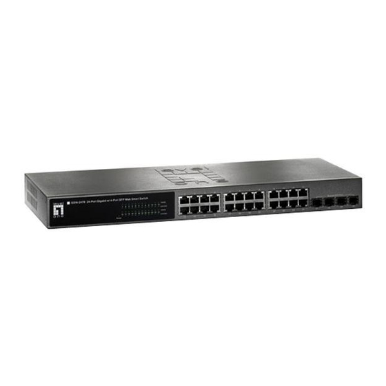
Figure 1-1 Front Panels ........1-1 Figure 1-2 Rear Panel (both switches) .
  • Page 15 IGURES Figure 6-18 Cable Diagnostics ......6-30 Figure 6-19 Trunk Membership ......6-32 Figure 6-20 Trunk Configuration .
  • Page 16 IGURES...
  • Page 17: About The Switch

    13 14 15 16 17 18 19 20 21 22 23 24 1000BASE-T/SFP Ports 10/100/1000 Mbps RJ-45 Ports Port Status Indicators GSW-1676 level GSW-1676 16 Port Gigabit w 4 Port SFP Web Smart Switch 1000 M Shared SFP Port Link/Act o n e 1000 M...
  • Page 18: Switch Architecture

    BOUT THE WITCH Switch Architecture The switches employ a wire-speed, non-blocking switching fabric. This permits simultaneous wire-speed transport of multiple packets at low latency on all ports. The switches also feature full-duplex capability on all ports, which effectively doubles the bandwidth of each connection. The switches use store-and-forward switching to ensure maximum data integrity.
  • Page 19: Description Of Hardware

    The Small Form Factor Pluggable (SFP) transceiver slots are shared with four of the RJ-45 ports (ports 21-24 on the GSW-2476, and ports 13-16 on the GSW-1676). In its default configuration, if an SFP transceiver (purchased separately) is installed in a slot and has a valid link on its port, the associated RJ-45 port is disabled and cannot be used.
  • Page 20: Table 1-1 Port Status Leds

    BOUT THE WITCH 4 Port SFP Web Smart Switch 10 11 1000 Link/Act 1000 Link/Act 13 14 15 16 17 18 19 20 21 22 23 24 Power Power Status LED Port Status LEDs Figure 1-3 Port LEDs and Power LED Table 1-1 Port Status LEDs Condition Status...
  • Page 21: Power Supply Socket

    EATURES AND ENEFITS Power Supply Socket The power socket is located on the rear panel of the switch. The standard power socket is for the AC power cord. 100-240V 50-60Hz 0.8A Figure 1-4 Power Supply Socket Features and Benefits Connectivity •...
  • Page 22: Expandability

    BOUT THE WITCH • IEEE 802.3-2005 Ethernet, Fast Ethernet, and Gigabit Ethernet. Expandability • 4 Small Form Factor Pluggable (SFP) transceiver slots (shared with 1000BASE-T ports). • Supports 1000BASE-SX, 1000BASE-LX and 1000BASE-ZX SFP transceivers. Performance • Transparent bridging. • Provides store-and-forward switching. •...
  • Page 23: Network Planning

    HAPTER ETWORK LANNING Introduction to Switching A network switch allows simultaneous transmission of multiple packets via non-crossbar switching. This means that it can partition a network more efficiently than bridges or routers. Switches have, therefore, been recognized as one of the most important building blocks for today’s networking technology.
  • Page 24: Application Examples

    ETWORK LANNING Application Examples The GSW-1676 and GSW-2476 are not only designed to segment your network, but also to provide a wide range of options in setting up network connections. Some typical applications are described below. Collapsed Backbone The GSW-1676 and GSW-2476 are an excellent choice for mixed Ethernet, Fast Ethernet, and Gigabit Ethernet installations where significant growth is expected in the near future.
  • Page 25: Central Wiring Closet

    PPLICATION XAMPLES Central Wiring Closet With 16 or 24 parallel bridging ports (i.e., 16 or 24 distinct collision domains), the switch can collapse a complex network down into a single efficient bridged node, increasing overall bandwidth and throughput. In the figure below, the 1000BASE-T RJ-45 ports on the GSW-2476 are providing 1 Gbps full-duplex connections for up to 24 local segments.
  • Page 26: Remote Connections With Fiber Cable

    ETWORK LANNING Remote Connections with Fiber Cable Fiber optic technology allows for longer cabling than any other media type. A 1000BASE-SX (MMF) link can connect to a site up to 550 meters away, a 1000BASE-LX (SMF) link up to 10 km, and a 1000BASE-ZX link up to 70 km.
  • Page 27: Making Vlan Connections

    PPLICATION XAMPLES Making VLAN Connections The switch supports VLANs that can be used to organize any group of network nodes into separate broadcast domains. VLANs confine broadcast traffic to the originating group, and can eliminate broadcast storms in large networks. This provides a more secure and cleaner network environment.
  • Page 28: Application Notes

    ETWORK LANNING Application Notes 1. Full-duplex operation only applies to point-to-point access (such as when a switch is attached to a workstation, server or another switch). When the switch is connected to a hub, both devices must operate in half-duplex mode. 2.
  • Page 29: Installing The Switch

    HAPTER NSTALLING THE WITCH Selecting a Site The GSW-1676 and GSW-2476 can be mounted in a standard 19-inch equipment rack or on a flat surface. Be sure to follow the guidelines below when choosing a location. • The site should: - be at the center of all the devices you want to link and near a power outlet.
  • Page 30: Ethernet Cabling

    NSTALLING THE WITCH Ethernet Cabling To ensure proper operation when installing the switches into a network, make sure that the current cables are suitable for 10BASE-T, 100BASE-TX or 1000BASE-T operation. Check the following criteria against the current installation of your network: •...
  • Page 31: Equipment Checklist

    Then, before beginning the installation, be sure you have all other necessary installation equipment. Package Contents • GSW-1676 or GSW-2476 • Four adhesive foot pads • Bracket Mounting Kit containing two brackets and eight screws for attaching the brackets to the switch •...
  • Page 32: Mounting

    NSTALLING THE WITCH Mounting The GSW-1676 and GSW-2476 can be mounted in a standard 19-inch equipment rack or on a desktop or shelf. Mounting instructions for each type of site follow. Rack Mounting Before rack mounting the switch, pay particular attention to the following factors: •...
  • Page 33: Figure 3-2 Attaching The Brackets

    OUNTING To rack-mount devices: 1. Attach the brackets to the device using the screws provided in the Bracket Mounting Kit. S h a r e d S F P P o r t Figure 3-2 Attaching the Brackets 2. Mount the device in the rack, using four rack-mounting screws (not provided).
  • Page 34: Desktop Or Shelf Mounting

    NSTALLING THE WITCH 3. If installing a single switch only, turn to “Connecting to a Power Source” at the end of this chapter. 4. If installing multiple switches, mount them in the rack, one below the other, in any order. Desktop or Shelf Mounting 1.
  • Page 35: Installing An Sfp Transceiver

    SFP T NSTALLING AN RANSCEIVER Installing an SFP Transceiver S h a r e d S F P P o r t Figure 3-5 Inserting an SFP Transceiver into a Slot The switch supports the following optional transceivers: • 1000BASE-SX (SGVT-0300) •...
  • Page 36: Connecting To A Power Source

    NSTALLING THE WITCH Connecting to a Power Source To connect a device to a power source: 1. Insert the power cable plug directly into the socket located at the back of the device. 100-240V 50-60Hz 0.8A Figure 3-6 Power Socket 2.
  • Page 37: Making Network Connections

    ETWORK ONNECTIONS Connecting Network Devices The GSW-1676 and GSW-2476 are designed to interconnect multiple segments (or collision domains). They can be connected to network cards in PCs and servers, as well as to hubs, switches or routers. They may also be connected to devices using optional SFP transceivers.
  • Page 38: Connecting To Pcs, Servers, Hubs And Switches

    AKING ETWORK ONNECTIONS Connecting to PCs, Servers, Hubs and Switches 1. Attach one end of a twisted-pair cable segment to the device’s RJ-45 connector. Figure 4-1 Making Twisted-Pair Connections 2. If the device is a PC card and the switch is in the wiring closet, attach the other end of the cable segment to a modular wall outlet that is connected to the wiring closet.
  • Page 39: Network Wiring Connections

    WISTED EVICES Network Wiring Connections Today, the punch-down block is an integral part of many of the newer equipment racks. It is actually part of the patch panel. Instructions for making connections in the wiring closet with this type of equipment follows.
  • Page 40: Fiber Optic Sfp Devices

    AKING ETWORK ONNECTIONS Fiber Optic SFP Devices An optional Gigabit SFP transceiver (1000BASE-SX, 1000BASE-LX or 1000BASE-ZX) can be used for a backbone connection between switches, or for connecting to a high-speed server. Each single-mode fiber port requires 9/125 micron single-mode fiber optic cable with an LC connector at both ends.
  • Page 41: Figure 4-3 Making Connections To Sfp Transceivers

    SFP D IBER PTIC EVICES 3. Connect one end of the cable to the LC port on the switch and the other end to the LC port on the other device. Since LC connectors are keyed, the cable can be attached in only one orientation. S h a r e d S F P P...
  • Page 42: Connectivity Rules

    AKING ETWORK ONNECTIONS Connectivity Rules When adding hubs (repeaters) to your network, please follow the connectivity rules listed in the manuals for these products. However, note that because switches break up the path for connected devices into separate collision domains, you should not include the switch or connected cabling in your calculations for cascade length involving other devices.
  • Page 43: 100 Mbps Fast Ethernet Collision Domain

    ONNECTIVITY ULES Table 4-3 Maximum 1000BASE-LX Fiber Optic Cable Length Fiber Diameter Fiber Cable Length Connector Bandwidth Range 9/125 micron 2 m - 10km single-mode fiber (7 ft - 6.4 miles) Table 4-4 Maximum 1000BASE-ZX Fiber Optic Cable Length Fiber Diameter Fiber Cable Length Connector...
  • Page 44: Cable Labeling And Connection Records

    AKING ETWORK ONNECTIONS Cable Labeling and Connection Records When planning a network installation, it is essential to label the opposing ends of cables and to record where each cable is connected. Doing so will enable you to easily locate inter-connected devices, isolate faults and change your topology without need for unnecessary time consumption.
  • Page 45: Initial Configuration

    HAPTER NITIAL ONFIGURATION To make use of the management features of your switch, you must first configure it with an IP address that is compatible with the network it is being installed in. This should be done before you permanently install the switch in the network.
  • Page 46: Figure 5-1 Login Page

    Note: The web interface examples in this guide are based on the GSW-2476. Other than the number of ports, there are no other differences between the GSW-2476 and GSW-1676. 5. Enter the default password “admin” and click on the Login button.
  • Page 47: Changing A Pc's Ip Address

    PC’ IP A HANGING A DDRESS Figure 5-2 LAN Settings Page No other configuration changes are required at this stage, but it is recommended that you change the administrator’s password before logging out. To change the password, click SYSTEM, Password, and then fill in all the fields on the Password Settings page before clicking on the APPLY button.
  • Page 48 NITIAL ONFIGURATION 4. In the Internet Protocol (TCP/IP) Properties dialog box, click to select Use the following IP address. Then type your intended IP address, Subnet mask, and Default gateway in the provided text boxes. 5. Click OK to save the changes. To change the IP address of a Windows XP PC: 1.
  • Page 49: Configuring The Switch

    HAPTER ONFIGURING THE WITCH Using the Web Interface This switch provides an embedded HTTP Web agent. Using a Web browser you can configure the switch and view statistics to monitor network activity. The Web agent can be accessed by any computer on the network using a standard Web browser (Internet Explorer 5.0 or above, or Firefox v1.5 or above).
  • Page 50: Navigating The Web Browser Interface

    ONFIGURING THE WITCH Navigating the Web Browser Interface To access the web-browser interface you must first enter a password. The administrator has read/write access to all configuration parameters and statistics. The default password for the administrator is “admin.” Note:If user input is not detected within five minutes, the current session is terminated.
  • Page 51: Figure 6-1 Home Page

    AVIGATING THE ROWSER NTERFACE Figure 6-1 Home Page Note: The web interface examples in this guide are based on the GSW-2476. Other than the number of ports, there are no other differences between the GSW-2476 and GSW-1676.
  • Page 52: Configuration Options

    ONFIGURING THE WITCH Configuration Options Configurable parameters have a dialog box or a drop-down list. Once a configuration change has been made on a page, be sure to click on the Apply button to confirm the new setting. The following table summarizes the web page configuration buttons.
  • Page 53: Main Menu

    Forces the switch to perform a power reset and 6-18 Defaults restores the original factory settings. Upgrade Firmware Upgrades the switch system firmware using a file 6-19 provided by LevelOne. Upload/Download Uploads or downloads the configuration file. 6-19 Configuration Restart Restarts the switch.
  • Page 54 ONFIGURING THE WITCH Main Menu (Continued) Menu Description Page Rate Limiting Sets the rate limiting parameters for ports. 6-25 Storm Control Sets the broadcast storm control parameters. 6-27 Port Mirroring Sets up the port mirroring features of the switch to 6-28 enable traffic monitoring.
  • Page 55 Main Menu (Continued) Menu Description Page Management Access Sets up management access filter. 6-69 Filter IGMP Snooping 6-71 Settings Sets up IGMP Snooping configuration. 6-73 Status Shows IGMP Snooping status. 6-73 SNMP 6-75 Settings Configures community strings and related trap 6-75 functions.
  • Page 56: Basic Information

    ONFIGURING THE WITCH Basic Information Displaying System Information You can easily identify the system by displaying the device name, location and contact information. Field Attributes System Information • System Name – Name assigned to the switch system. • Number of Ports – Number of built-in ports. •...
  • Page 57 ASIC NFORMATION 10hdx: 10 Mbps half duplex. 10fdx: 10 Mbps full duplex. 100hdx: 100 Mbps half duplex. 100fdx: 100 Mbps full duplex. 1000fdx: 1000 Mbps full duplex. • Flow Control Status – Indicates whether flow control is enabled or disabled. (IEEE 802.3x, or Back-Pressure) •...
  • Page 58: Figure 6-3 Status Overview

    ONFIGURING THE WITCH Figure 6-3 Status Overview 6-10...
  • Page 59: Showing Port Statistics

    ASIC NFORMATION Showing Port Statistics You can display statistics on network traffic from the ports. These statistics can be used to identify potential problems with the switch (such as a faulty port or unusually heavy loading). All values displayed have been accumulated since the last system reboot, but can be reset to zero by clicking the CLEAR button.
  • Page 60 ONFIGURING THE WITCH Port Statistics (Continued) Parameter Description Received Multicast Packets The number of packets, delivered by this sub-layer to a higher (sub-)layer, which were addressed to a multicast address at this sub-layer. Received Broadcast Packets The number of packets, delivered by this sub-layer to a higher (sub-)layer, which were addressed to a broadcast address at this sub-layer.
  • Page 61 ASIC NFORMATION Port Statistics (Continued) Parameter Description Collisions The best estimate of the total number of collisions on this Ethernet segment. Received Bytes Total number of bytes of data received on the network. This statistic can be used as a reasonable indication of Ethernet utilization.
  • Page 62: Figure 6-4 Port Statistics

    ONFIGURING THE WITCH Web – Click STATUS, Statistics. Figure 6-4 Port Statistics 6-14...
  • Page 63: Displaying The System Name

    ’ IP A ETTING THE WITCH DDRESS Displaying the System Name You can identify the system by displaying the device name. Field Attributes • Switch Name – A name assigned to the switch system. Web – Click System, Name. Figure 6-5 System Name Setting the Switch’s IP Address This section describes how to configure an IP interface for management access over the network.
  • Page 64: Manual Configuration

    ONFIGURING THE WITCH • Gateway IP Address – IP address of the gateway router between this device and management stations that exist on other network segments. (Default: 0.0.0.0) • Management VLAN – ID of the configured VLAN (1-4093, no leading zeroes). By default, all ports on the switch are members of VLAN 1.
  • Page 65: Configuring The Logon Password

    ONFIGURING THE OGON ASSWORD Configuring the Logon Password The administrator has write access for all parameters governing the onboard agent. You should therefore assign a new administrator password as soon as possible, and store it in a safe place. Field Attributes •...
  • Page 66: Tools

    ONFIGURING THE WITCH Tools On the Tools page, you can restore the switch to its default settings, upgrade the firmware of the switch, or restart the switch. Restore to Factory Defaults Forces the switch to restore the original factory settings. To reset the switch, select “Reset to Factory Defaults”...
  • Page 67: Upload/Download Configuration

    “Browse” button to select the firmware file. Click the APPLY button to upgrade the selected switch firmware file. You can download firmware files for your switch from the Support section of the LevelOne web site at www.level1.com. Web – Click System, Tools, Reset to Factory Defaults.
  • Page 68: Restart Switch

    ONFIGURING THE WITCH Browse button to choose a file location on the web management station, or to find a saved configuration file. Figure 6-10 Upload/Download Configuration Restart Switch Web – Click SYSTEM, Tools, Restart Switch. To restart the switch, click APPLY.
  • Page 69: Static Mac

    TATIC Static MAC Switches store the MAC addresses for all known devices in the attached network. This information is used to forward traffic directly between the inbound and outbound ports. All the MAC addresses learned by monitoring traffic are stored in a dynamic address table, which removes (ages out) any addresses that are not “seen”...
  • Page 70: Figure 6-12 Static Mac Address Configuration

    ONFIGURING THE WITCH Web – Click System, Static MAC. Enter the MAC address, VLAN ID, and click ADD to add a new static MAC address. Then mark the port to which this MAC address is bound, and click Apply. Figure 6-12 Static MAC Address Configuration Counter Configuration This page allows specific statistics to be selected for monitoring.
  • Page 71: Figure 6-13 Counter Configuration

    TATIC Figure 6-13 Counter Configuration 6-23...
  • Page 72: Port Configuration

    ONFIGURING THE WITCH Port Configuration Ports Settings You can use the Port Configuration page to manually set the speed, duplex mode, and flow control. Field Attributes • Enable Jumbo Frames – This switch provides more efficient throughput for large sequential data transfers by supporting jumbo frames on Gigabit Ethernet ports up to 9216 bytes.
  • Page 73: Configuring Rate Limits

    ONFIGURATION Figure 6-14 Port Configuration Configuring Rate Limits This function allows the network manager to control the maximum rate for traffic transmitted or received on an interface. Rate limiting is configured on interfaces at the edge of a network to limit traffic into or out of the switch.
  • Page 74: Figure 6-15 Rate Limiting

    ONFIGURING THE WITCH option from this list, click APPLY, and then view the options in the Input/Output Bandwidth Limit drop-down box for any of the ports. (Options: 128 kbps, 1 Mbps, 10 Mbps, 30 Mbps, 100 Mbps) • Enable Rate Limiting – Enables input or output rate limiting for the selected interface.
  • Page 75: Storm Control

    ONFIGURATION Storm Control Broadcast storms may occur when a device on your network is malfunctioning, or if application programs are not well designed or properly configured. If there is too much broadcast traffic on your network, performance can be severely degraded or everything can come to complete halt.
  • Page 76: Port Mirroring

    ONFIGURING THE WITCH Figure 6-16 Port Broadcast Control Port Mirroring You can mirror traffic from any source port to a target port for real-time analysis. You can then attach a logic analyzer or RMON probe to the target port and study the traffic crossing the source port in a completely unobtrusive manner.
  • Page 77: Figure 6-17 Port Mirroring

    ONFIGURATION Note: If the total ingress bandwidth exceeds the mirror port’s egress bandwidth, packets will eventually be dropped on ingress to the switch, which means they will not reach the mirror port or their intended destination port. Input rate-limiting in conjunction with port flow-control should be used to ensure that the total ingress bandwidth never exceeds the egress bandwidth.
  • Page 78: Cable Diagnostics

    ONFIGURING THE WITCH Cable Diagnostics You can perform cable diagnostics for all ports or selected ports to diagnose any cable faults (short, open, etc.) and feedback a distance to the fault. Field Attributes • Cable Diagnostics – Cable diagnostics is performed on a per-port basis.
  • Page 79: Trunk Membership

    ONFIGURATION Trunk Membership You can create multiple links between devices that work as one virtual, aggregate link. A port trunk offers a dramatic increase in bandwidth for network segments where bottlenecks exist, as well as providing a fault-tolerant link between two devices. This page allows you to create a maximum of eight trunks of up to eight ports each.
  • Page 80: Figure 6-19 Trunk Membership

    ONFIGURING THE WITCH Web – Click TRUNKS, Membership. To assign a port to a trunk, click the required trunk number, then click APPLY. Figure 6-19 Trunk Membership 6-32...
  • Page 81: Trunk Configuration

    ONFIGURATION Trunk Configuration This page allows you to configure the speed, duplex mode, and flow control for a trunk. Field Attributes • Trunk – Indicates trunk identifier. • Speed/Duplex – Allows you to manually set the port speed and duplex mode for all ports in the trunk.
  • Page 82: Figure 6-21 Trunk Rate Limiting

    ONFIGURING THE WITCH • Trunk – Indicates trunk identifier. • Trunk Speed – Indicates the trunk speed. • Enable Input/Output Rate Limiting - Mark the box to enable Input/ Output Rate Limiting. • Input/Output Limit – Sets the threshold for trunk bandwidth measured in number of frames per second.
  • Page 83: Lacp Setup

    ONFIGURATION LACP Setup This page allows you to enable 802.3ad Link Aggregation Control Protocol (LACP) for the selected port. You can configure any number of ports on the switch to use LACP. If ports on another device are also configured for LACP, the switch and the other device will negotiate a trunk link between them.
  • Page 84: Displaying Lacp Status

    ONFIGURING THE WITCH Web – Click TRUNKS, LACP Setup. Enable LACP on each port to be configured as a member of an LAG. Leave the administrative key set to a null value to allow the switch to automatically configure this attribute, or set it a specific value to maintain more precise control over the ports which will be connected to another device.
  • Page 85: Figure 6-23 Lacp Status Overview

    ONFIGURATION Aggregation Information • Aggregation Group – Identifier for a local link aggregation group. • Partner MAC Address – Physical address of device at other end of link. • Local Ports Aggregated – Local ports participating in this LAG. • Seconds Since Last Change – Time since the last LACP packet was received.
  • Page 86: Configuring Vlan Groups

    ONFIGURING THE WITCH Configuring VLAN Groups The 802.1Q VLAN Configuration page allows you to create and delete VLANs (Virtual LANs), and set up or modify VLAN group members. Introduction to VLANs VLANs are logical partitions of the physical LAN. You can use VLANs to increase network performance or improve internal network security.
  • Page 87 VLAN G ONFIGURING ROUPS different customers use the same internal VLAN IDs. This is accomplished by inserting Service Provider VLAN (SPVLAN) tags into the customer’s frames when they enter the service provider’s network, and then stripping the tags when the frames leave the network. QinQ tunneling expands VLAN space by using this VLAN-in-VLAN hierarchy, preserving the customer’s original tagged packets, and adding SPVLAN tags to each frame (also called double tagging).
  • Page 88: Figure 6-24 802.1Q Vlan Configuration

    ONFIGURING THE WITCH Web – Click VLANS, VLAN Membership. Figure 6-24 802.1Q VLAN Configuration 6-40...
  • Page 89: Figure 6-25 Vlan Group Settings

    VLAN G ONFIGURING ROUPS Web – After creating a new VLAN, the following screen displays. Assign the ports and trunks associated with the VLAN, and click Apply. Figure 6-25 VLAN Group Settings 6-41...
  • Page 90: Configuring Vlan Interfaces

    ONFIGURING THE WITCH Configuring VLAN Interfaces You can configure VLAN behavior for specific interfaces, including the default VLAN identifier (PVID) and accepted frame types. The 802.1Q Per Port Configuration page allows you to change the VLAN parameters for individual ports. Each row of the table corresponds to one port or static trunk;...
  • Page 91 VLAN G ONFIGURING ROUPS and untagged packets. Any received packets that are untagged are assigned to the default VLAN. Any tagged packets will be dropped unless the port is a member of the VLAN identified by the VLAN tag in the packet.
  • Page 92: Figure 6-26 Vlan Settings

    ONFIGURING THE WITCH Web – Click VLANS, VLAN Port Configuration. Fill in the required settings for each interface, and click Apply. Figure 6-26 VLAN Settings 6-44...
  • Page 93: Qos Settings

    ETTINGS QoS Settings QoS (Quality of Service) is a mechanism which is used to prioritize certain traffic as it is forwarded through the switch. Both the queue service mode (strict or weighted round robin), and the method of classifying the priority of ingress traffic can be configured on this page.
  • Page 94 ONFIGURING THE WITCH to a Class of Service value by the switch, and the traffic then sent to the corresponding output queue. If the QoS mode is set to 802.1p, and the ingress packet type is IPv4, then priority processing will be based on the 802.1p value in the ingress packet. For an untagged packet, the default port priority is used for priority processing (i.e., CoS value 0, which maps to the Normal Queue).
  • Page 95 ETTINGS Custom if you want to set each value individually. Note that end-stations, like PCs, are not usually VLAN aware, so they do not create VLAN-tagged frames. As a result, 802.1p is not an ideal method to use when there are a lot of PCs connected to the switch. •...
  • Page 96: Figure 6-27 Qos Settings

    ONFIGURING THE WITCH Figure 6-27 QoS Settings When the QoS Mode is set to 802.1p, the 802.p Configuration table is displayed as shown below. Figure 6-28 802.1p Configuration 6-48...
  • Page 97: Figure 6-29 Dscp Configuration

    ETTINGS When the QoS Mode is set to DSCP, the DSCP Configuration table is displayed as shown below. Figure 6-29 DSCP Configuration 6-49...
  • Page 98: Rstp

    ONFIGURING THE WITCH RSTP The Spanning Tree Algorithm (STA) can be used to detect and disable network loops, and to provide backup links between switches, bridges or routers. This allows the switch to interact with other bridging devices (that is, an STA-compliant switch, bridge or router) in your network to ensure that only one route exists between any two stations on the network, and provide backup links which automatically take over when a primary link goes down.
  • Page 99: Configuring Rstp

    RSTP alternate route that can be used when a node or port fails, and retaining the forwarding database for ports insensitive to changes in the tree structure when reconfiguration occurs. Configuring RSTP Use the RSTP Configuration page to specify global or port-specific parameters for the Rapid Spanning Tree Protocol.
  • Page 100 ONFIGURING THE WITCH This delay is required because every device must receive information about topology changes before it starts to forward frames. In addition, each port needs time to listen for conflicting information that would make it return to a discarding state; otherwise, temporary data loops might result.
  • Page 101 RSTP during reconfiguration events, does not cause the spanning tree to initiate reconfiguration when the interface changes state, and also overcomes other STA-related timeout problems. However, remember that Edge Port should only be enabled for ports connected to an end-node device. (Default: Enabled) •...
  • Page 102: Figure 6-30 Rstp Configuration

    ONFIGURING THE WITCH Web – Click RSTP, Settings. Set any required system or port-specific attributes for RSTP, and click APPLY. Figure 6-30 RSTP Configuration 6-54...
  • Page 103: Displaying Rstp Status

    RSTP Displaying RSTP Status Use the RSTP Status page to display global and port-specific status and attribute settings for the Rapid Spanning Tree Protocol. Field Attributes RSTP Bridge Overview • Hello Time – Interval (in seconds) at which the root device transmits a configuration message.
  • Page 104 ONFIGURING THE WITCH to this port, the manual setting for Edge Port will be overridden, and the port will instead function as a point-to-point connection. • P2P Port – Shows if this port is functioning as a Point-to-Point connection to exactly one other bridge. The switch can automatically determine if the interface is attached to a point-to-point link or to shared media.
  • Page 105: Figure 6-31 Rstp Status Overview

    802.1X Web – Click RSTP, Status. Figure 6-31 RSTP Status Overview 802.1X Network switches can provide open and easy access to network resources by simply attaching a client PC. Although this automatic configuration and access is a desirable feature, it also allows unauthorized personnel to easily intrude and possibly gain access to sensitive network data.
  • Page 106 ONFIGURING THE WITCH This switch uses the Extensible Authentication Protocol over LANs (EAPOL) to exchange authentication protocol messages with the client, and a remote RADIUS authentication server to verify user identity and access rights. When a client (i.e., Supplicant) connects to a switch port, the switch (i.e., Authenticator) responds with an EAPOL identity request.
  • Page 107: Configuring 802.1X

    802.1X Configuring 802.1X Use the 802.1X Configuration page to specify global or port-specific parameters for the IEEE 802.1X Port Authentication Protocol. Field Attributes System Settings • Mode - Enables or disables 802.1X globally for all ports on the switch. The 802.1X protocol must be enabled globally for the switch before the port settings are active.
  • Page 108 ONFIGURING THE WITCH either 802.1X-aware or otherwise. (This is the default setting.) Force-Unauthorized - Forces the port to deny access to all clients, either 802.1X-aware or otherwise. • Port State - Administrative state for port access control. • Reset - The two available options include: Re-Authenticate - Schedules a re-authentication to whenever the quiet-period of the port runs out.
  • Page 109: Figure 6-32 802.1X Configuration

    802.1X Figure 6-32 802.1X Configuration 6-61...
  • Page 110: 802.1X Statistics

    ONFIGURING THE WITCH 802.1X Statistics Use the 802.1X Statistics page to display statistics for dot1x protocol exchanges for any port. Field Attributes • Port Statistics - Statistics can be viewed on a per-port basis. Select the port that you want to view here. Authenticator Counters •...
  • Page 111 802.1X AUTHENTICATED, as a result of the Backend Authentication state machine indicating successful authentication of the Supplicant. • AuthFailWhileAuthenticating – The number of times that the state machine transitions from AUTHENTICATING to HELD, as a result of the Backend Authentication state machine indicating authentication failure.
  • Page 112 ONFIGURING THE WITCH • backendAuthSuccesses – The number of times that the state machine receives an EAP-Success message from the Authentication Server. Indicates that the Supplicant has successfully authenticated to the Authentication Server. Dot1x MIB Counters • EapolFramesRx – The number of valid EAPOL frames of any type that have been received by this Authenticator.
  • Page 113: Figure 6-33 802.1X Statistics

    802.1X Web – Click 802.1X, Statistics. Figure 6-33 802.1X Statistics 6-65...
  • Page 114: Security

    ONFIGURING THE WITCH Security IP Filter On this page, you can set up a source IP Filter on all or some ports. It is used to block unwanted access and provide access to the network for either a specific source IP address or a specific subnet. Field Attributes •...
  • Page 115: Port Security

    ECURITY Figure 6-34 IP Filter Configuration Port Security Port security is a feature that allows you to configure a port with one or more MAC addresses that are authorized to access the network through that port. When port security is enabled on a port, the switch stops learning new MAC addresses on the specified port when it has reached a configured maximum number.
  • Page 116 ONFIGURING THE WITCH Field Attributes • Port - The number of the port. • Allowed Number of Learned MAC Addresses - Set the maximum of MAC addresses that can be learned by this port. The options are shown below. No Limit - No limit is set on the number of dynamically learned MAC address.
  • Page 117: Management Access Filter

    ECURITY Web – Click Security, Port Security. Set the number of allowed MAC addresses and the response to a detected intrusion, then click APPLY. Figure 6-35 Port Security Management Access Filter This page enables you to set up a management access filter on the switch. With the Management Access Filter Configuration table, you can create a list of up to 8 IP addresses or IP address groups that are allowed management access to the switch through the web interface or SNMP.
  • Page 118: Figure 6-36 Management Access Filter Configuration

    ONFIGURING THE WITCH Web – Click Security, Management Access Filter. Enter a specific IP address or an address range, and click APPLY. Figure 6-36 Management Access Filter Configuration 6-70...
  • Page 119: Igmp Snooping

    IGMP S NOOPING IGMP Snooping The switch can use Internet Group Management Protocol (IGMP) to filter multicast traffic. IGMP Snooping monitors IGMP service requests passing between multicast clients and servers, and dynamically configures the ports which need to receive the multicast traffic. You can configure the switch to forward multicast traffic intelligently.
  • Page 120 ONFIGURING THE WITCH Depending on your network connections, IGMP snooping may not always be able to locate the IGMP querier. Therefore, if the IGMP querier is a known multicast router/ switch connected over the network to a port on this switch, you can manually configure the port (and a specified VLAN) to join all the current multicast groups supported by the attached router.
  • Page 121: Displaying Igmp Statistics

    IGMP S NOOPING Web – Click IGMP Snoop, Settings. Modify the required global or VLAN-specific attributes, and click APPLY. Figure 6-37 IGMP Snooping Configuration Displaying IGMP Statistics Use the IGMP Snooping Statistics page to show IGMP Snooping statistics for each VLAN. Field Attributes •...
  • Page 122: Figure 6-38 Igmp Snooping Status

    ONFIGURING THE WITCH • v2 Reports - The number of received v2 Report packets. • v3 Reports - The number of received v3 Report packets. • v3 Leave - The number of v3 leave packets received. Web – Click IGMP Snoop, Status. Figure 6-38 IGMP Snooping Status 6-74...
  • Page 123: Snmp

    SNMP SNMP Use the SNMP Settings page to configure the Simple Network Management Protocol (SNMP), including enabling the local SNMP agent on this switch, specifying a trap manager, and setting the access strings. Simple Network Management Protocol (SNMP) is a communication protocol designed specifically for managing devices on a network.
  • Page 124: Figure 6-39 Snmp Configuration

    ONFIGURING THE WITCH • SNMP Trap Community - Community string sent with the notification operation. Web – Click SNMP, Settings. Set the local SNMP agent status, specify a trap manager, set the community access stings, and click APPLY. Figure 6-39 SNMP Configuration 6-76...
  • Page 125: Troubleshooting

    Check connections between the switch, the power cord, and the wall outlet. • Contact your dealer for assistance. • Contact LevelOne Technical Support. Link LED is Off • Verify that the switch and attached device are powered • Be sure the cable is plugged into both the switch and corresponding device.
  • Page 126: Power And Cooling Problems

    ROUBLESHOOTING Power and Cooling Problems If the power indicator does not turn on when the power cord is plugged in, you may have a problem with the power outlet, power cord, or internal power supply. However, if the unit powers off after running for a while, check for loose power connections, power losses or surges at the power outlet, and verify that the fans on the unit are unobstructed and running prior to shutdown.
  • Page 127: Reset The Switch

    ESET THE WITCH Reset the Switch As situation requires, you might want to reset the switch and to restore to the default settings. To reset the switch: 1. Unplug the power cord from the power socket. 2. Unplug all cables from the ports. 3.
  • Page 128 ROUBLESHOOTING...
  • Page 129: Cables

    PPENDIX ABLES Twisted-Pair Cable and Pin Assignments For 10BASE-T/100BASE-TX connections, a twisted-pair cable must have two pairs of wires. For 1000BASE-T connections the twisted-pair cable must have four pairs of wires. Each wire pair is identified by two different colors. For example, one wire might be green and the other, green with white stripes.
  • Page 130: 10Base-T/100Base-Tx Pin Assignments

    ABLES 10BASE-T/100BASE-TX Pin Assignments Use unshielded twisted-pair (UTP) or shielded twisted-pair (STP) cable for RJ-45 connections: 100-ohm Category 3 or better cable for 10 Mbps connections, or 100-ohm Category 5 or better cable for 100 Mbps connections. Also be sure that the length of any twisted-pair connection does not exceed 100 meters (328 feet).
  • Page 131: Straight-Through Wiring

    WISTED ABLE AND SSIGNMENTS Straight-Through Wiring If the twisted-pair cable is to join two ports and only one of the ports has an internal crossover (MDI-X), the two pairs of wires must be straight-through. (When auto-negotiation is enabled for any RJ-45 port on the switch, you can use either straight-through or crossover cable to connect to any device type.) You must connect all four wire pairs as shown in the following diagram to...
  • Page 132: Crossover Wiring

    ABLES Crossover Wiring If the twisted-pair cable is to join two ports and either both ports are labeled with an “X” (indicating MDI-X) or neither port is labeled with an “X” (which indicates MDI), a crossover must be implemented in the wiring.
  • Page 133: 1000Base-T Pin Assignments

    WISTED ABLE AND SSIGNMENTS 1000BASE-T Pin Assignments All 1000BASE-T ports support automatic MDI/MDI-X operation, so you can use straight-through cables for all network connections to PCs or servers, or to other switches or hubs. The table below shows the 1000BASE-T MDI and MDI-X port pinouts. These ports require that all four pairs of wires be connected.
  • Page 134: Adjusting Existing Category 5 Cabling To Run 1000Base-T

    ABLES Note that when testing your cable installation, be sure to include all patch cables between switches and end devices. Adjusting Existing Category 5 Cabling to Run 1000BASE-T If your existing Category 5 installation does not meet one of the test parameters for 1000BASE-T, there are basically three measures that can be applied to try and correct the problem: 1.
  • Page 135: Specifications

    PPENDIX PECIFICATIONS Physical Characteristics Ports GSW-1676: 12 10/100/1000BASE-T, with auto-negotiation 4 10/100/1000BASE-T shared with 4 SFP transceiver slots. GSW-2476: 20 10/100/1000BASE-T, with auto-negotiation 4 10/100/1000BASE-T shared with 4 SFP transceiver slots. Network Interface Ports 1-16/24: RJ-45 connector, auto MDI/X 10BASE-T: RJ-45 (100-ohm, UTP cable; Category 3 or better) 100BASE-TX: RJ-45 (100-ohm, UTP cable;...
  • Page 136: Switch Features

    PECIFICATIONS Weight 3.72 kg (8.44 lbs) Size 44.0 x 17.1 x 4.3 cm (17.0 x 6.7 x 1.7 in.) Temperature Operating: 0 to 40 °C (32 to 104 °F) Storage: -40 to 70 °C (-40 to 158 °F) Humidity Operating: 10% to 90% (non-condensing) AC Input 100 to 240 V, 50-60 Hz, 0.8 A Power Supply...
  • Page 137: Management Features

    ANAGEMENT EATURES Management Features In-Band Management Web manager Software Loading HTTP in-band Standards IEEE 802.3-2005 Ethernet, Fast Ethernet, Gigabit Ethernet IEEE 802.1Q Virtual LAN IEEE 802.1X, Port-Based Network Access Control, 2001 ISO/IEC 8802-3 Compliances CE Mark Emissions FCC Class A...
  • Page 138 PECIFICATIONS...
  • Page 139: Glossary

    LOSSARY 10BASE-T IEEE 802.3 specification for 10 Mbps Ethernet over two pairs of Category 3 or better UTP cable. 100BASE-TX IEEE 802.3u specification for 100 Mbps Fast Ethernet over two pairs of Category 5 or better UTP cable. 1000BASE-LX IEEE 802.3z specification for Gigabit Ethernet over two strands of 50/125, 62.5/125 or 9/125 micron core fiber cable.
  • Page 140 LOSSARY Bandwidth The difference between the highest and lowest frequencies available for network signals. Also synonymous with wire speed, the actual speed of the data transmission along the cable. Collision A condition in which packets transmitted over the cable interfere with each other.
  • Page 141 LOSSARY Full Duplex Transmission method that allows two network devices to transmit and receive concurrently, effectively doubling the bandwidth of that link. Gigabit Ethernet A 1000 Mbps network communication system based on Ethernet and the CSMA/CD access method. IEEE Institute of Electrical and Electronic Engineers. IEEE 802.3 Defines carrier sense multiple access with collision detection (CSMA/CD) access method and physical layer specifications.
  • Page 142: Network Diameter

    LOSSARY Layer 2 Data Link layer in the ISO 7-Layer Data Communications Protocol. This is related directly to the hardware interface for network devices and passes on traffic based on MAC addresses. Light emitting diode used for monitoring a device or network condition. Link Segment Length of twisted-pair or fiber cable joining a pair of repeaters or a repeater and a PC.
  • Page 143 LOSSARY Redundant Power Supply (RPS) A backup power supply unit that automatically takes over in case the primary power supply should fail. RJ-45 Connector A connector for twisted-pair wiring. Switched Ports Ports that are on separate collision domains or LAN segments. Telecommunications Industry Association Transmission Control Protocol/Internet Protocol (TCP/IP) Protocol suite that includes TCP as the primary transport protocol, and IP...
  • Page 144 LOSSARY Glossary-6...
  • Page 145: Index

    NDEX Numerics compliances EMC C-3 10 Mbps connectivity rules 4-7 connectivity rules 100 Mbps connectivity rules 4-7 10 Mbps 4-7 1000 Mbps connectivity rules 4-6 100 Mbps 4-7 1000BASE-LX fiber cable lengths 4-7 1000 Mbps 4-6 1000BASE-SX fiber cable lengths 4-6 contents of package 3-3 1000BASE-T cooling problems A-2...
  • Page 146 NDEX IEEE 802.3 Ethernet 1-6 main menu 6-5 IEEE 802.3ae 10 Gigabit Ethernet 1-6 management IEEE 802.3u Fast Ethernet 1-6 agent 1-2 IEEE 802.3z Gigabit Ethernet 1-6 features 1-6 indicators, LED 1-3 SNMP 1-2 ingress filtering 6-42 mounting the switch installation in a rack 3-4 connecting devices to the switch 4-2...
  • Page 147 NDEX rate limits port 6-26 rate limits, setting 6-25 temperature within a rack 3-4 rear panel receptacles 1-5 troubleshooting RJ-45 port 1-3 in-band access A-2 connections 4-1 power and cooling problems A-2 pinouts B-5 switch indicators A-1 RSTP trunk interface settings 6-52 static 6-35 rubber foot pads, attaching 3-6 twisted-pair connections 4-1...
  • Page 148 NDEX Index-4...
  • Page 150 GSW-1676 GSW-2476 E052010-CS-R02 149100011100H...

This manual is also suitable for:

Gsw-2476

Table of Contents