Table of Contents
Advertisement
Quick Links
Instructional Booklet IB02102006E
Type MVS (previously WLI)
Effective May 2011
Supersedes April 2006
Description
Introduction . . . . . . . . . . . . . . . . . . . . . . . . . . . . . 2
Receiving, handling, and storage . . . . . . . . . . . . 4
Installation . . . . . . . . . . . . . . . . . . . . . . . . . . . . . . 5
Operation . . . . . . . . . . . . . . . . . . . . . . . . . . . . . . 16
Maintenance . . . . . . . . . . . . . . . . . . . . . . . . . . . 17
Duplex switchgear configuration . . . . . . . . . . . . 23
Motor operation . . . . . . . . . . . . . . . . . . . . . . . . . 23
(shunt trip) . . . . . . . . . . . . . . . . . . . . . . . . . . 25
bus connections and connections to
switch terminal pads . . . . . . . . . . . . . . . . . . 28
Common renewal parts . . . . . . . . . . . . . . . . . . . 28
Page
Advertisement
Table of Contents

Related Manuals for Eaton MVS


Summary of Contents for Eaton MVS
-
Page 1: Table Of Contents
(shunt trip) . . . . . . . . . . . . . . . . . . . . . . . . . . 25 MVS switchgear bolt tightness for bus connections and connections to switch terminal pads . -
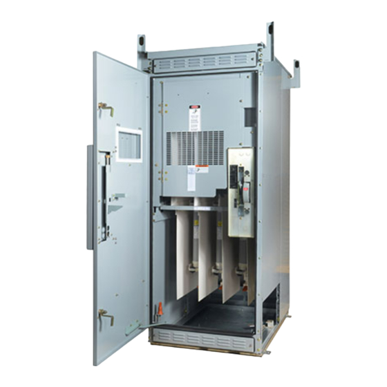
Page 2: Metal-Enclosed Switchgear
A nameplate is located inside the small access door of each type of industry standards IEEE C37.20.3 and ANSI C37.57 MVS switchgear vertical section (see Figure 1) . Contained on this nameplate are the Eaton master parts list number and all the This switchgear vertical section is suitable for use on a circuit necessary switchgear ratings . - Page 3 Effective May 2011 4.76 kV, 15.0 kV, 27.0 kV, and 38.0 kV Safety features Type MVS load interrupter switchgear has several built-in features to reduce hazards and to provide proper operating sequences . WARNING EXCEEDING THE NAMEPLATE RATINGS OF MVS SWITCHGEAR MAy CAUSE PROPERTy DAMAGE, SEVERE INJURy, OR DEATH.
-
Page 4: Receiving, Handling, And Storage
Handling accidentally left inside the unit . Removable lifting lugs are provided on the top of the MVS structure for insertion of hooks to lift the complete structure . This is the only Revision recommended method of moving the MVS structure . -
Page 5: Installation
Access to MVS switch vertical sections containing switches Step 5e: Bolted connections should be tightened to the torque values Each MVS switch is shipped from the factory in the “Closed” posi- given on page 28 . tion to maintain alignment during shipping and handling . The safety... - Page 6 Cables are NOT factory pre-cut to the proper length . The installer • MUST cut them to fit . Holes are predrilled in the side of the MVS structure to match the Factory cables are unshielded . For 15 kV, 27kV, and 38 kV holes provided in the transformer .
- Page 7 Outdoor switchgear a large number of commercially available cable support devices Step 1e: Position the units side by side . The holes in the MVS side that can be fastened to this channel(s) to support the cable so sheet around the bus cutout will match the holes in the metal-clad that the cable weight is not hanging on the switchgear terminals .
- Page 8 Instructional Booklet IB02102006E Type MVS (previously WLI) metal-enclosed switchgear— Effective May 2011 4.76 kV, 15.0 kV, 27.0 kV, and 38.0 kV Figure 6. Bottom Cable Entrance (Energy Source), Rear Access Figure 8. Unfused Bottom Cable Exit (to Load), Rear Access Figure 7.
- Page 9 Instructional Booklet IB02102006E Type MVS (previously WLI) metal-enclosed switchgear— Effective May 2011 4.76 kV, 15.0 kV, 27.0 kV, and 38.0 kV Figure 10. Top Cable Entrance (Energy Source), Front Access Figure 11. Bottom Cable Entrance (Energy Source), Front Access eaton corporation www.eaton.com...
- Page 10 Instructional Booklet IB02102006E Type MVS (previously WLI) metal-enclosed switchgear— Effective May 2011 4.76 kV, 15.0 kV, 27.0 kV, and 38.0 kV Figure 12. Unfused Top Cable Exit (to Load), Front Access Figure 14. Fused Top Cable Exit (to Load), Front Access Figure 13.
- Page 11 For incoming or outgoing terminations, these approved materials • are not supplied by Eaton and must be obtained and installed by others as identified in the definitions on this page . For connections involving shipping splits within an MVS switchgear •...
- Page 12 . Do not use any abrasives or solvents . Securing MVS switchgear assemblies to foundations Step 2e: Apply one turn of 1 .00 inch (25 .4 mm) tape so that half All anchoring hardware and necessary devices are to be supplied by of the tape is on the conductor and half is on the pre-insulation .
- Page 13 Figure 18. Floor Plan of a Typical Seismic MVS 4.76 kV or 15 kV Figure 17. Floor Plan of a Typical Non-Seismic MVS 4.76 kV or Switchgear Vertical Section 15 kV Switchgear Vertical Section eaton corporation www.eaton.com...
- Page 14 Figure 19. Floor Plan of a Typical Indoor MVS 27 kV or 38 kV Figure 20. Floor Plan of a Typical Outdoor MVS 27 kV or 38 kV Vertical Section, Non-Seismic or Seismic Vertical Section, Non-Seismic or Seismic eaton corporation www.eaton.com...
- Page 15 Step 3e: Remove the superstructure from the shipping pallet and WARNING then remove all covers . Shipment of more than one MVS vertical section will be tagged to identify superstructures with their cor- EACH SWITCH IS PROPERLy ADJUSTED AT THE FACTORy BEFORE SHIPMENT.
-
Page 16: Operation
(see Figure 21) . create a hazard . Step 2e: The MVS switch should be in the “Open” position . This is Key interlocking accomplished by rotating the operating handle downward . -
Page 17: Maintenance
“Megger” readings indicates it to be advisable . This field test should be made before the main cables are connected and The MVS switch should be inspected once a year or after its rated should not exceed the values in Table 3 . - Page 18 Figure 25. Closed-Open-Stop Adjustment Bolts otee: There are two blade and break jaw configurations used on the “MVS” (previously the WLI) switch design . The original design used a flat break jaw with a “hook” cutout on the bottom and each blade had two indentations (“bullets”) that bore onto the break jaw surfaces .
- Page 19 Step 3e: If the switch is equipped with key interlocking, care must be taken when replacing the switch mechanism cover to ensure that it is properly repositioned . Elongated holes in the MVS side sheet allow for vertical adjustment . The key interlock bolt must clear the “Open-Closed”...
- Page 20 Instructional Booklet IB02102006E Type MVS (previously WLI) metal-enclosed switchgear— Effective May 2011 4.76 kV, 15.0 kV, 27.0 kV, and 38.0 kV Step 1e: Loosen the four hinge bolts and the two break jaw bolts . Replacement procedures Insert the removable handle in the maintenance hub on the shaft Main blade subassembly and break jaw replacement and “Close”...
- Page 21 Instructional Booklet IB02102006E Type MVS (previously WLI) metal-enclosed switchgear— Effective May 2011 4.76 kV, 15.0 kV, 27.0 kV, and 38.0 kV Method B Main spring replacement For the following procedure, refer to Figure 29 . Step 1e: To disengage the main spring, remove the switch mechanism cover (see Figure 23) .
- Page 22 Insulated bus material is made from NORYL, a high-performance the blade and hinge . engineering thermoplastic . Eaton grease 53701AI should be applied to the spring rod(s) at the stationary end pivots . WARNING If the handle casting and/or the spring lever is dragging the switch...
-
Page 23: Duplex Switchgear Configuration
120 Vac 24 Vdc 48 Vdc 125 Vdc Time to open or close an MVS switch with an integral motor operator is about 5 seconds for the AC versions and about 10 seconds for the DC versions . Receiving and startup For MVS switches, units are shipped with the linear actuator installed . - Page 24 4.76 kV, 15.0 kV, 27.0 kV, and 38.0 kV WARNING WARNING OPERATING AN MVS SWITCH WITH A KEy INTERLOCK BOLT EXTENDED DEFEATING OR DISENGAGING SAFETy INTERLOCKS ON AN MVS SWITCH WILL RESULT IN EQUIPMENT DAMAGE AND MAy ALSO EXPOSE A PERSON THAT IS CONNECTED TO A POWER SOURCE MAy RESULT IN PROPERTy TO BODILy INJURy OR DEATH.
-
Page 25: Electromechanical Stored Energy Release
CAUTION shaft to “Close” or to “Open” the switch (see Figure 35) . This feature is only available on 4 .76 kV or 15 kV class MVS switches . CHANGING THE SWITCH POSITION WITH THE SWITCH OPERATING HANDLE WILL RESULT IN DAMAGE TO THE SWITCH. - Page 26 Instructional Booklet IB02102006E Type MVS (previously WLI) metal-enclosed switchgear— Effective May 2011 4.76 kV, 15.0 kV, 27.0 kV, and 38.0 kV Electrical Trigger Coil Electrical Trigger Trigger Coil Latch Teeter Trigger Assembly Teeter Latch Assembly Trip Link Hand Trip Trip Link...
- Page 27 The blade and arc chute alignment procedures are the same for (see Figure 39) . the standard MVS switch described in the “Maintenance” section . However, before the maintenance hub may be used, the following steps must be taken .
-
Page 28: Mvs Switchgear Bolt Tightness For
As required two-conductor polyester/nylon, 8.00-inch centers 4.76/15 kV MVS bus brace, As required 260C266H03 two-conductor polyester/epoxy, 8.00-inch centers Fuse live parts kit, RBA200 4.76 kV (MVS) As required 98A1125G22 Fuse live parts kit, RBA200 15 kV (MVS) As required 98A1125G23 Fuse live parts kit (WLI), RBA200 25.8 kV or 38 kV...
Need help?
Do you have a question about the MVS and is the answer not in the manual?
Questions and answers