
Related Manuals for AXIOMTEK GOT-5152T-830


Summary of Contents for AXIOMTEK GOT-5152T-830
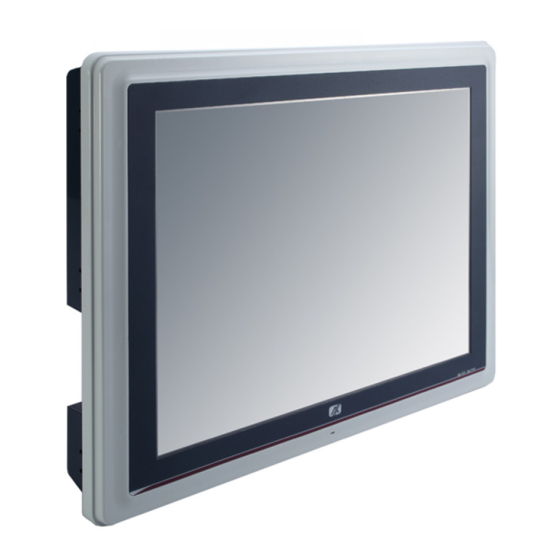
- Page 1 GOT-5152T-830 All-in-One 15” XGA TFT Fanless Touch Panel ® Computer with Intel Atom N270 Processor Onboard User’s Manual...
- Page 2 Axiomtek does not warrant or assume any legal liability or responsibility for the accuracy, completeness or usefulness of any information in this document. Axiomtek does not make any commitment to update the information in this manual.
-
Page 3: Safety Approvals
Safety Approvals CE Marking FCC Class A FCC Compliance This equipment has been tested in compliance with the limits for a Class A digital device, pursuant to Part 15 of the FCC Rules. These limits are meant to provide reasonable protection against harmful interference in a residential installation. -
Page 4: Safety Precautions
Turn OFF the system power before cleaning. Clean the system using a cloth only. Do not spray any liquid cleaner directly onto the screen. The GOT-5152T-830 may come with or w/o a touchscreen. Although the touchscreen is chemical resistant, it is recommended that you spray the liquid cleaner on a cloth first before wiping the screen. - Page 5 When handling boards and components, wear a wrist- grounding strap, available from most electronic component stores. Trademarks Acknowledgments Axiomtek is a trademark of Axiomtek Co., Ltd. IBM, PC/AT, PS/2, VGA are trademarks of International Business Machines Corporation. ® ™...
-
Page 6: Table Of Contents
Table of Contents Disclaimers ..................ii Safety Approvals ................iii Safety Precautions ................ iv CHAPTER 1 INTRODUCTION ..............1 General Description ............ 1 Specifications .............. 3 1.2.1 Main CPU Board ............3 1.2.2 I/O System ..............3 1.2.3 System Specification ........... 4 Dimensions .............. - Page 7 System ..............67 Touch Screen ............68 4.2.1 Specification .............. 68 4.2.2 Driver Installation- Windows XP ........ 68 Embedded O.S............71 4.3.1 Windows XP Embedded ........... 71 4.3.2 Windows CE.NET 6.0 ..........72...
- Page 8 MEMO: viii...
-
Page 9: Chapter 1 Introduction
Mini card slot for wireless module. Its excellent ID and friendly user interface make it a professional yet easy-to-use panel computer. The GOT-5152T-830 is an ideal for space- limited applications in factory automation, machine maker operating systems, building automation, and more. - Page 10 GOT-5152T5152T User’s Manual GOT-5152T-830: 15” TFT XGA Fanless Touch Panel Computer Reliable and Stable Design The GOT-5152T-830 adopts a fanless cooling system ™ and a CompactFlash card, which makes it suitable for vibration environments. Embedded O.S. Supported ®...
-
Page 11: Specifications
GOT-5152T5152T User’s Manual Specifications 1.2.1 Main CPU Board ○ Intel Atom N270 1.6GHz processor with FSB 533MHz onboard System Chipset 945GSE + ICH7M BIOS America Megatrends BIOS System Memory One 200-pin DDR2 SO-DIMM socket ... -
Page 12: System Specification
One SATA Power connector GOT-5152T-830: 10VDC to 30VDC with phoenix power connector GOT-5152T-830-J: External 60W AC Adapter with screw type connector 1.2.3 System Specification 15” TFT LCD Heat Dispensing Design Disk drive housing: ... - Page 13 GOT-5152T5152T User’s Manual NOTE All specifications and images are subject to change without notice. NOTE If the operation temperature is higher than 3 5℃ , wide temperature DRAM recommended to be used on the device. Introduction...
-
Page 14: Dimensions
GOT-5152T5152T User’s Manual Dimensions This diagram shows you dimensions and outlines of the GOT- 5152T-830. Introduction... - Page 15 GOT-5152T5152T User’s Manual Introduction...
- Page 16 GOT-5152T5152T User’s Manual Introduction...
- Page 17 GOT-5152T5152T User’s Manual Introduction...
-
Page 18: I/O Outlets
GOT-5152T5152T User’s Manual I/O Outlets Please refer to the following illustration for I/O locations of the GOT-5152T-830. Function POWER SWITCH (ATX) Power Input connector (phoenix type) Power Input connector (screw type) 2 X USB 2.0 COM 4 (RS-232) COM 3 (RS-232) -
Page 19: Packing List
GOT-5152T5152T User’s Manual Packing List W hen you receive the GOT-5152T-830, the bundled package should contain the following items: GOT-5152T-830 x 1 Panel Mount Kit x 10 Driver CD x1 Wall-Mount Kit x1 Power Adapter & power cord (for GOT-5152T-830-J) If you can not find the package or any items are missing, please contact Axiomtek distributors immediately. - Page 20 GOT-5152T5152T User’s Manual MEMO: Introduction...
-
Page 21: Chapter 2 Hardware Installation
Hard disk Dram Wireless LAN Card CF card Installation The GOT-5152T-830 provides one CF slot for users to install ™ CompactFlash card. Please refer to the following instructions for installation: Step 1 Turn off the system, and unplug the power cord. - Page 22 GOT-5152T5152T User’s Manual tep 2 Remove the cover of CF socket. Step 3 Locate the CompactFlash socket, and insert the card into the socket. Hardware Installation...
-
Page 23: Serial Ports Interface
GOT-5152T User’s Manual Serial Ports Interface The GOT-5152T-830 has two onboard serial ports, COM1 (RS- 232/ 422/ 485) and COM 2,3,4 (RS-232). The following table shows you the pin assignments of this connector: Signal Signal Data Carrier Detect (DCD) Data Set Ready (DSR) - Page 24 GOT-5152T5152T User’s Manual W hen COM1 is set to RS-422 or RS-485, the pin assignments are listed below: Signal Name Pin # RS-422 RS-485 DATA- DATA+ No connector No connector No connector No connector No connector No connector No connector No connector No connector No connector...
-
Page 25: Ethernet
GOT-5152T User’s Manual Ethernet The GOT-5152T-830 is equipped with a high performance Plug and Play Ethernet interface, full compliant with IEEE 802.3 standard, and can be connected with a RJ-45 LAN connector. Please refer to detailed pin assignment list below:... -
Page 26: Mountings - Panel/Wall/Desktop/Vesa
Panel, W all, Desktop and VESA mountings. 2.4.1 Panel Mounting The GOT-5152T-830 is designed for panel mount application. A set of standard mounting kit are bundled with the system package that you can use it to mount the GOT-5152T-830. Hardware Installation... -
Page 27: Wall-Mounting
GOT-5152T User’s Manual 2.4.2 Wall-Mounting The GOT-5152T-830 is designed for W all mounting application. Please refer to the following steps: Fix wall mount bracket on the back of the unit. Hardware Installation... -
Page 28: Desktop-Mounting
GOT-5152T5152T User’s Manual 2.4.3 Desktop-Mounting GOT-5152T-830 designed desktop mounting application. Please refer to the following steps: Step 1 Find out the screws as marked on the back side of chassis. Hardware Installation... - Page 29 GOT-5152T User’s Manual Step 2 Assemble the desktop stand to the chassis, and fix the screws. CAUTION:USE RECOMMENDED/SUITABLE MOUNTING APPARATUS TO AVOID RISK OF INJURY. Hardware Installation...
-
Page 30: Vesa-Arm Mounting
GOT-5152T5152T User’s Manual 2.4.4 VESA-ARM Mounting CAUTION:USE RECOMMENDED/SUITABLE MOUNTING APPARATUS TO AVOID RISK OF INJURY. Step 1 Find out the screws as marked on the back side of chassis. Hardware Installation... - Page 31 GOT-5152T User’s Manual Step 2 Assemble the VESA-ARM to the back side of the chassis, and fix the screws. Step 3 VESA mounting Installation completed. Hardware Installation...
-
Page 32: Hdd Installation
GOT-5152T5152T User’s Manual HDD Installation The GOT-5152T-830 provides a convenient Hard Disk Drive (HDD) bracket for users to install 2.5” SATA HDD. Please follow the steps: 1. Unscrew eight screws to remove the rear chassis. Hardware Installation... - Page 33 GOT-5152T User’s Manual 2. Unscrew 4 screws from the HDD bracket, and take out HDD bracket. 3. Screw the 2.5” HDD, together with the HDD Mylar, to the HDD bracket. Hardware Installation...
- Page 34 GOT-5152T5152T User’s Manual 4. Fix the HDD bracket into the system, and plug the data and power cable to HDD. Installation complete. Power Data Hardware Installation...
-
Page 35: Dram Installation
GOT-5152T User’s Manual DRAM Installation The GOT-5152T-830 provides one 200-pin DDR2 SODIMM socket that support system memory up to 2GB. Please follow steps below to install the memory modules: Open the back cover and find mainboard ( SBC87830). Hardware Installation... - Page 36 GOT-5152T5152T User’s Manual Push down latches on each side of the DIMM socket. Install the memory module into the socket and push it firmly down until it is fully seated. The socket latches are levered upwards and clipped on to the edges of the DIMM. Hardware Installation...
-
Page 37: Wireless Lan Card Installation
GOT-5152T User’s Manual Wireless LAN Card Installation The GOT-5152T-830 provides one Mini card slot for user to install one wireless LAN card. W hen installing the wireless LAN card, refer to the following instructions and illustration: Open the back cover and find mainboard (SBC87830). - Page 38 GOT-5152T5152T User’s Manual The socket latches are clipped on to the edges of the Mini card.Install wireless LAN card to the socket. Hardware Installation...
- Page 39 GOT-5152T User’s Manual Find the built-in Antenna cable. There are two connectors on wireless LAN card. One is MAIN, and the other is auxiliary. Connect antenna cable to MAIN connector on wireless LAN card. Hardware Installation...
- Page 40 GOT-5152T5152T User’s Manual MEMO: Hardware Installation...
-
Page 41: Chapter 3 Ami Bios Setup Utility
GOT-5152T User’s Manual CHAPTER 3 AMI BIOS SETUP UTILITY This chapter provides users with detailed description how to set up basic system configuration through the AMI BIOS setup utility. Starting To enter the setup screens, follow the steps below: Turn on the computer and press the <Del> key immediately. After you press the <Delete>... - Page 42 GOT-5152T5152T User’s Manual The Left and Right <Arrow> keys allow you to select Left/Right a setup screen. The Up and Down <Arrow> keys allow you to select Up/Down a setup screen or sub-screen. + The Plus and Minus <Arrow> keys allow you to Plus/Minus change the field value of a particular setup item.
-
Page 43: Main Menu
GOT-5152T User’s Manual Main Menu W hen you first enter the Setup Utility, you will enter the Main setup screen. You can always return to the Main setup screen by selecting the Main tab. There are two Main Setup options. They are described in this section. -
Page 44: Advanced Menu
GOT-5152T5152T User’s Manual Advanced Menu The Advanced menu allows users to set configuration of the CPU and other system devices. You can select any of the items in the left frame of the screen to go to the sub menus: ... - Page 45 GOT-5152T User’s Manual Configure advanced CPU settings This screen shows the CPU Configuration, and you can change the value of the selected option. Max CPUID Value Limit You can enable this item to let legacy operating systems boot even without support for CPUs with extended CPU ID functions.
- Page 46 GOT-5152T5152T User’s Manual This item helps you enable or disable the Intel SpeedStep Technology. Intel (R) C-STATE tech Use this item to enable or disable the C-State technology. Enhanced C-States This item allows you to enable or disable any available enhanced C-states ( C1E, C2E, C3E, C4E and Hard C4E).
- Page 47 GOT-5152T User’s Manual ATA/IDE Configuration Use this item to specify the integrated IDE controll er. There are three options for your selection: Disabled, Compatible and Enhanced. Legacy IDE Channels W hen the ATA/IDE Configuration is set to Compatible, this item will be displayed.
- Page 48 GOT-5152T5152T User’s Manual Serial Port1 Address This item specifies the base I/O port address and Interrupt Request address of serial port 1. The Optimal setting is 3F8/IRQ4. The Fail-Safe default setting is 3F8. Serial Port1 IRQ This item specifies the IRQ used by the serial port 1. ...
- Page 49 GOT-5152T User’s Manual Hardware Health Configuration This screen shows the Hardware Health Configuration, and a description of the selected item appears on the right side of the screen. System Temperature/CPU Temperature These items display the temperature of CPU and System, Vcore, etc.
- Page 50 GOT-5152T5152T User’s Manual ACPI Settings You can use this screen to select options for the ACPI Settings, and change the value of the selected option. A description of the selected item appears on the right side of the screen. AMI BIOS Setup Utility...
- Page 51 GOT-5152T User’s Manual APM Configuration You can use this screen to select options for the APM Configuration, and change the value of the selected option. A description of the selected item appears on the right side of the screen. ...
- Page 52 GOT-5152T5152T User’s Manual Video Power Down Mode This option specifies the Power State that the video subsystem enters when the BIOS places it in a power saving state after the specified period of display inactivity has expired. The default setting is Suspend. This setting prevents the BIOS from initiating any power Disabled saving modes concerned with the video display or...
- Page 53 GOT-5152T User’s Manual Throttle Slow Clock Ratio Use this item to specify the speed of the system clock when running the power saving states. Power Button Mode This option specifies how the externally mounted power button on the front of the computer chassis is used. The default setting is On/Off.
- Page 54 GOT-5152T5152T User’s Manual MPS Configuration This screen shows the MPS (Multi Processor Specification) Configuration, and you can change its value. A description of the selected item appears on the right side of the screen. MPS Revision Use this item to select MPS (Multi Processor Specification) Revision 1.1 or 1.4.
- Page 55 GOT-5152T User’s Manual PCI Express Configuration This screen shows the PCI Express Configuration, and you can change its value. A description of the selected item appears on the right side of the screen. Active State Power-Management Use this item to enable or disable the function of Active State Power-Management to provide you with lower power consumption.
- Page 56 GOT-5152T5152T User’s Manual AMI BIOS Setup Utility...
- Page 57 GOT-5152T User’s Manual USB Configuration You can use this screen to select options for the USB Configuration, and change the value of the selected option. A description of the selected item appears on the right side of the screen. ...
-
Page 58: Pci Pnp Menu
GOT-5152T5152T User’s Manual PCI PnP Menu The PCI PnP menu allows users to change the advanced settings for PCI/PnP devices. AMI BIOS Setup Utility... - Page 59 GOT-5152T User’s Manual Clear NVRAM Use this item to clear the data in the NVRAM (CMOS). Here are the options for your selection, No and Yes. Plug & Play O/S When the setting is No, Use this item to configure all the devices in the system.
- Page 60 GOT-5152T5152T User’s Manual Allocate IRQ to PCI VGA This item allows BIOS to choose an IRQ to assign for the PCI VGA card. Here are the options for your selection, No and Yes. Palette Snooping Some old graphic controllers need to “snoop” on the VGA palette, and then map it to their display as a way to provide boot information and VGA compatibility.
-
Page 61: Boot Menu
GOT-5152T User’s Manual Boot Menu The Boot menu allows users to change boot options of the system. You can select any of the items in the left frame of the screen to go to the sub menus: Boot Settings Configuration ... - Page 62 GOT-5152T5152T User’s Manual Boot Settings Configuration Quick Boot Enabling this item lets the BIOS skip some power on self tests (POST). The default setting is Enabled. Quiet Boot Set this item to allow the computer system to display the Disabled POST messages.
- Page 63 GOT-5152T User’s Manual PS/2 Mouse Support This item determines if the BIOS should reserve IRQ12 for the PS/2 mouse or allow other devices to make use of this IRQ. Here are the options for your selection, Auto, Enabled and Disabled. ...
- Page 64 GOT-5152T5152T User’s Manual Removable Drives Use this screen to view the removable drives in the system. The BIOS will attempt to arrange the removable drive boot sequence automatically. You can also change the booting sequence. AMI BIOS Setup Utility...
- Page 65 GOT-5152T User’s Manual Lan Boot Settings Configuration The Lan Boot Settings Configuration can enable or disable Lan Boot ROM to allow the system boot on LAN. AMI BIOS Setup Utility...
-
Page 66: Security Menu
GOT-5152T5152T User’s Manual Security Menu The Security menu allows users to change the security settings for the system. Supervisor Password This item indicates whether a supervisor password has been set. If the password has been installed, Installed displays. If not, Not Installed displays. - Page 67 GOT-5152T User’s Manual Boot Sector Virus Protection This option is near the bottom of the Security Setup screen. The default setting is Disabled. Set this item to prevent the Boot Sector Virus Protection. Disabled This is the default setting. Select Enabled to enable boot sector protection.
-
Page 68: Chipset Menu
GOT-5152T5152T User’s Manual Chipset Menu The Chipset menu allows users to change the advanced chipset settings. You can select any of the items in the left frame of the screen to go to the sub menus: North Bridge Configuration ... - Page 69 GOT-5152T User’s Manual North Bridge Configuration DRAM Frequency This item allows you to control the Memory Clock. Configure DRAM Timing by SPD This item can enable or disable DRAM timing by SPD (Serial Presence Detect) device, which is a small EEPROM chip on the memory module, containing important information about the module speed, size, addressing mode and various parameters.
- Page 70 GOT-5152T5152T User’s Manual AMI BIOS Setup Utility...
- Page 71 GOT-5152T User’s Manual South Bridge Configuration AMI BIOS Setup Utility...
- Page 72 GOT-5152T5152T User’s Manual USB Function This item allows you to enable or disable USB function. USB 2.0 Controller This item allows you to enable or disable the USB 2.0 controller. Audio Controller This item allows you to enable or disable the audio support. ...
-
Page 73: Exit Menu
GOT-5152T User’s Manual Exit Menu The Exit menu allows users to load your system configuration with optimal or failsafe default values 0 Save Changes and Exit When you have completed the system configuration changes, select this option to leave Setup and reboot the computer so the new system configuration parameters can take effect. - Page 74 GOT-5152T5152T User’s Manual Load Optimal Defaults It automatically sets all Setup options to a complete set of default settings when you select this option. The Optimal settings are designed for maximum system performance, but may not work best for all computer applications. In particular, do not use the Optimal Setup options if your computer is experiencing system configuration problems.
-
Page 75: Chapter 4 Drivers Installation
GOT-5152T User’s Manual CHAPTER 4 DRIVERS INSTALLATION System GOT-5152T-830 supports Windows XP/7. To facilitate the installation of system driver, please carefully read the instructions in this chapter before start installing. Insert Driver CD and select the “\Drivers”. Select all files and follow the installing procedure. -
Page 76: Touch Screen
Active: 24.6mA / Idle Mode: 13.4mA Consumption 4.2.2 Driver Installation- Windows XP The GOT-5152T-830 provides a touch screen driver that users can install it under the operating system Windows XP. To facilitate installation of the touch screen driver, you should read the instructions in this chapter carefully before you attempt installation. - Page 77 GOT-5152T User’s Manual Follow the installing procedure and press OK. Click Start menu and select “PenMount Utilities”; and then, a “PenMount Control Panel” pops out. Select the “Standard Calibrate” Drivers Installation...
- Page 78 GOT-5152T5152T User’s Manual Calibration: To adjust the display with touch panel, click “Calibration” and follow the calibrate point to do calibration; there are five points on screen for calibration. Press OK. Drivers Installation...
-
Page 79: Embedded O.s
GOT-5152T User’s Manual Embedded O.S. The GOT-5152T provides the W indows XP Embedded and W indows CE.Net 6.0. The O.S. is supported devices which are listed below. 4.3.1 Windows XP Embedded Here are supported onboard devices: Onboard Multi I/O SATA HDD ... -
Page 80: Windows Ce.net 6.0
GOT-5152T5152T User’s Manual 4.3.2 Windows CE.NET 6.0 Here are supported onboard devices: Onboard Multi I/O SATA HDD PS2 Keyboard and mouse CRT/LCD display 10/100/1000 base-T Ethernet Compact Flash Onboard Audio Audio Touch Screen ...
Need help?
Do you have a question about the GOT-5152T-830 and is the answer not in the manual?
Questions and answers