
Related Manuals for AXIOMTEK GOT321W-502-PCT


Summary of Contents for AXIOMTEK GOT321W-502-PCT
- Page 1 GOT321W-502-PCT All-in-One 21.5” FHD Fanless 10-Point Multi-Touch PANEL PC User’s Manual...
- Page 2 Axiomtek does not make any commitment to update any information in this manual. Axiomtek reserves the right to change or revise this document and/or product at any time without notice. No part of this document may be reproduced, stored in a retrieval system, or transmitted in any forms or by any means, electronic, mechanical, photocopying, recording, among others, without prior written permission from Axiomtek Co., Ltd.
-
Page 3: Safety Precautions
Most electronic components are sensitive to static electrical charge. Disconnect the power cord from the GOT321W-502-PCT series prior to any installation. Be sure both the system and all external devices are turned off. Sudden surge of power could ruin sensitive components. Make sure the GOT321W-502-PCT Series is properly grounded. -
Page 4: Table Of Contents
Table of Contents Disclaimers ..................... ii Safety Precautions ..................iii Section 1 Introduction ..........1 General Descriptions ................1 Specifications ..................2 Dimensions and Outlines ..............5 I/O Outlets .................... 7 Packing List ..................8 Section 2 Hardware and Installation ...... 9 Board Layout .................. - Page 5 4.1.1 Installing System Drivers ............... 31 Touch Screen ..................32 Appendix A Watchdog Timer ........33 About Watchdog Timer ................33 How to Use Watchdog Timer ............... 33 WDT Sample Program ................. 34 ITE 8620 Datasheet about Watch Dog register description ...... 35...
- Page 6 This page is intentionally left blank.
-
Page 7: Introduction
Packing List General Descriptions The GOT321W-502-PCT has adopted a 21.5" TFT FHD LCD with 250-nit brightness and supports LGA1151 Socket 6/7th generation Intel® Core™ i7/i5/i3/Celeron processor that can support Windows 7, Windows 7 Embedded, Windows 8, Windows 8 Embedded, Windows 10, Windows 10 IoT and variety applications. -
Page 8: Specifications
WLAN antenna supported (optional) The GOT321W-502-PCT comes with two Mini Card slots as an add-on option to connect a wireless LAN card under 802.11 a/b/g/n protocols, or with other 3G/GPRS applications, etc. These slots also come with three optional fixed rotational WLAN/3G antennas for wireless network connection. - Page 9 GOT321W-502-PCT User’s Manual I/O System Standard I/O 2 x RS-232/422/485 4 x USB 3.0 2 x RJ-45 1 x HDMI 1.4b 1 x VGA 1 x Display Port 1.2 2 x Power input ...
- Page 10 GOT321W-502-PCT User’s Manual Operating temperatures 0°C to 40°C Relative humidity 20% to 90% @ 40°C, Non-condensing System power input DC power input: 12V/19V/24V DC-in with Phoenix power connector AC-DC Power (19V adapter) NOTE: All specifications and images are subject to change without notice.
-
Page 11: Dimensions And Outlines
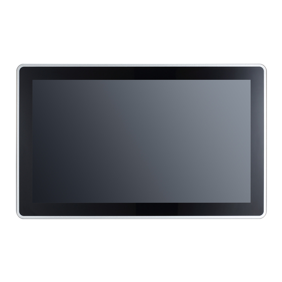
GOT321W-502-PCT User’s Manual Dimensions and Outlines Diagram 1-1 shows the dimensions and outlines of the front panel of the GOT321W-502-PCT Diagram 1-1 Front dimensions and outline of the GOT321W-502-PCT Front dimensions: 547.59 x 339.05 x 75.6 mm Introduction... - Page 12 GOT321W-502-PCT User’s Manual Diagram 1-2 Back outline of the GOT321W-502-PCT Diagram 1-3 Cutting-out dimensions of the GOT321W-502-PCT Cut out dimensions: 534.69 x 326.15 mm Introduction...
-
Page 13: I/O Outlets
GOT321W-502-PCT User’s Manual I/O Outlets Please refer to Figures 1-2 and 1-3 for I/O locations of the GOT321W-502-PCT. Figure 1-2 Bottom view of the GOT321W-502-PCT Figure 1-3 Side view of the GOT321W-502-PCT Figure 1-4 Back view of the GOT321W-502-PCT Introduction... -
Page 14: Packing List
Phoenix connector x 1 (DC power version only) Panel mount kit x 16 Screws x 4 ( fix HDD under the HDD bracket) NOTE: Barebone system will include thermal paste. Please contact an Axiomtek distributor immediately if any of the above-mentioned items is missing. Introduction... -
Page 15: Hardware And Installation
GOT321W-502-PCT User’s Manual Section 2 Hardware and Installation The GOT321W-502-PCT has provided rich I/O ports for users to meet different demands; for example, for example, in a case of flexible I/O. This Section is describing hardware installation, including the following subsections: ... -
Page 16: Jumper And Connector Settings
Diagram 2-1 Definitions of pin settings Pins 1-2 open Pins 1-2 close Pins 1-2 close All pins open Before applying power to GOT321W-502-PCT, please make sure all of the jumpers and connectors are in default position as Diagram 2-1. Diagram 2-2 Motherboard component position... -
Page 17: Clr_Cmos (Clear Cmos Jumper)
GOT321W-502-PCT User’s Manual 2.2.1 CLR_CMOS (Clear CMOS Jumper) Use this jumper to clear the BIOS configuration and reset the CMOS values to factory defaults. To clear the CMOS values, use a metal object like a screwdriver to touch the two pins for a few seconds. -
Page 18: Ethernet Connector
GOT321W-502-PCT User’s Manual 2.2.3 Ethernet Connector There are two RJ-45 connectors, LAN1 and LAN2, inside the GOT321W-502-PCT. Ethernet connection can be established by plugging one end of the Ethernet cable into this RJ-45 connector and the other end (phone jack) to a 1000/100/10-Base-T hub. -
Page 19: Mounting Methods
GOT321W-502-PCT User’s Manual Mounting Methods There are four ways to install the GOT321W-502-PCT, namely: panel/ VESA/ wall/ desktop mount. The GOT321W-502-PCT is designed for panel mount application. To mount the GOT321W-502-PCT, the standard set of mounting kit (16 pcs included in the system packaging) is needed. - Page 20 GOT321W-502-PCT User’s Manual Alternatively, the GOT321W-502-PCT can be installed by way of VESA mount which is in the dimensions of 100x100 mm. Simply fix four screws to fasten the kit from the back chassis, as shown in Diagram 2-5. Additionally, users can otherwise go for wall mount as an option, as shown in Diagram 2-6.
-
Page 21: Hardware Installation
GOT321W-502-PCT User’s Manual Hardware Installation 2.4.1 Installing a HDD The GOT321W-502-PCT provides a convenient hot-swappable Hard Disk Drive (HDD) bracket for users to install a 2.5” (support 7mm & 9.5mm) SATA HDD. Please follow the steps: Step 1 Refer to Section 2.1 to open the back cover. -
Page 22: Installing A Dram
Completing installation by fastening the screw. (see Figure 2-6). Figure 2-6 Connecting cables to connectors 2.4.2 Installing a DRAM The GOT321W-502-PCT provides two DDR4 SO-DIMM socket that supports system memory up to 32GB. Please follow three steps below to install a memory module: Step 1 Refer to Section 2.1 to open the back cover. -
Page 23: Installing A Cpu
GOT321W-502-PCT User’s Manual Step 3 Insert a DRAM into the DIMM socket, and then push it down firmly until it is clipped with the socket (as shown in Figure 2-8). Figure 2-8 Inserting a DRAM into the DIMM 2.4.3 Installing a CPU The CPU is socket type on main board that supports Intel 6/7 core i processor. -
Page 24: Installing A Wireless Lan Card
GOT321W-502-PCT User’s Manual 2.4.4 Installing a Wireless LAN Card The GOT321W-502-PCT comes with two Mini card slots for users to install wireless LAN cards. Please refer to the following instructions and illustration for the installation of the wireless LAN card. - Page 25 GOT321W-502-PCT User’s Manual Step 3 Locate the antenna cable and connect it to the wireless LAN card (see Figure 2-12). Figure 2-12 Connecting the antenna to the wireless LAN card Step 4 Remove the antenna plug from the top of back cover, and then install the antenna on the antenna connector (see Figures 2-13 and 2-14).
-
Page 26: Connecting The Power Input
GOT321W-502-PCT User’s Manual Connecting the Power Input The GOT321W-502-PCT is equipped with a Phoenix type of power connector which adopts 12V/19~24V DC-in. Please follow the signs on the power connector to connect DC power source (see Figure 2-15). Figure 2-15 The power connector -:Power negative... -
Page 27: Ami Bios Setup Utility
GOT321W-502-PCT User’s Manual Section 3 AMI BIOS Setup Utility This Section provides users with detailed descriptions about how to set up basic system configurations through the AMI BIOS setup utility. Navigation Keys The BIOS setup/utility uses a key-based navigation system called hot keys. Most of the hot keys for the BIOS setup utility can be used at any time during the setup navigation process. -
Page 28: M.i.t
GOT321W-502-PCT User’s Manual M.I.T Figure 3-1 M.I.T M.I.T. Current Status This screen provides information on CPU/memory frequencies/parameters. AMI BIOS Setup Utility... -
Page 29: System Information
GOT321W-502-PCT User’s Manual System Information Figure 3-2 System Information This section provides information on your motherboard model and BIOS version. You can also select the default language used by the BIOS and manually set the system time. System Language Selects the default language used by the BIOS. -
Page 30: Bios Feature
GOT321W-502-PCT User’s Manual BIOS Feature Figure 3-3 BIOS Feature Bootup NumLock State Enables or disables Numlock feature on the numeric keypad of the keyboard after the POST. (Default: On) Security Option Specifies whether a password is required every time the system boots, or only when you enter BIOS Setup. -
Page 31: Peripherals
GOT321W-502-PCT User’s Manual Peripherals Figure 3-3 Peripherals OnBoard LAN Controller (LAN1) Enables or disables the onboard LAN function. (Default: Enabled) If you wish to install a 3rd party add-in network card instead of using the onboard LAN, set this item to Disabled. -
Page 32: Chipset
GOT321W-502-PCT User’s Manual Chipset Figure 3-4 Chipset VT-d (Note) Enables or disables Intel® Virtualization Technology for Directed I/O. (Default: Disabled) DVMT Pre-Allocated Allows you to set the onboard graphics memory size. Options are: 32M~512M. (Default: 64M) DVMT Total Gfx Mem Allows you to allocate the DVMT memory size of the onboard graphics. -
Page 33: Power Management
GOT321W-502-PCT User’s Manual Power Management Figure 3-5 Power Management Power Mode AT/ATX power modes can both be used on the GOT317-502 Panel PC. The selection is made through an AT/ATX switch on the I/O interface panel. [AT] The system will automatically start when plug in power by one of switch and BIOS setting is AT mode condition. - Page 34 GOT321W-502-PCT User’s Manual ErP (Energy-related Product) If system enables the ErP function, it will shut down all of the standby power (USB / LAN / PCIe devices etc.) when it’s turn off. Only the power button can turn on system. (Default: Disabled) This function is for some countries or regions to compliant the energy regulations.
-
Page 35: Save & Exit
GOT321W-502-PCT User’s Manual Save & Exit Figure 3-6 Save & Exit Save & Exit Setup Press <Enter> on this item and select Yes. This saves the changes to the CMOS and exits the BIOS Setup program. Select No or press <Esc> to return to the BIOS Setup Main Menu. - Page 36 GOT321W-502-PCT User’s Manual This page is intentionally left blank. AMI BIOS Setup Utility...
-
Page 37: Driver And Installation
Driver and Installation Operating System The GOT321W-502-PCT supports Windows 7 / Windows 8.1 / WES7 / WE8S / Windows 10 / Windows 10 IoT Enterprise. To facilitate the installation of system driver, please carefully read the instructions in this Section before start installing. -
Page 38: Touch Screen
GOT321W-502-PCT User’s Manual Touch Screen The GOT321W-502-PCT uses the 5-wire analog resistive (flat front bezel type). There are the specification and driver installation which are listed below. Table 4-1 Touch screen specifications Touch Screen 5-wire Analog Resistive type Touch Screen Controller... -
Page 39: Appendix A Watchdog Timer
GOT321W-502-PCT User’s Manual Appendix A Watchdog Timer About Watchdog Timer Software stability is major issue in most application. Some embedded systems are not watched by human for 24 hours. It is usually too slow to wait for someone to reboot when computer hangs. -
Page 40: Wdt Sample Program
GOT321W-502-PCT User’s Manual WDT Sample Program Setting Watch dog steps as below: 1. Select to Logical Device to 0x7 2. Register 0x72 defination - Bit 7 : WDT time out value select 1 1 : Second 0 : Minute - Bit 6 : WDT Output through KRST Enable... -
Page 41: Ite 8620 Datasheet About Watch Dog Register Description
GOT321W-502-PCT User’s Manual ITE 8620 Datasheet about Watch Dog register description 1. Watch Dog Timer Control Register (Index=71h,Default=00h) Description WDT is reset upon a CIR interrupt WDT is reset upon a KBC(Mouse) interrupt WDT is reset upon a KBC(Keyboard) interrupt...
Need help?
Do you have a question about the GOT321W-502-PCT and is the answer not in the manual?
Questions and answers