Table of Contents
Advertisement
Quick Links
Advertisement
Table of Contents

Related Manuals for AXIOMTEK GOT3156T-834


Summary of Contents for AXIOMTEK GOT3156T-834
- Page 1 GOT3156T-834 All-in-One 15” XGA TFT Fanless PANEL PC User’s Manual...
- Page 2 Axiomtek does not make any commitment to update the information in this manual. Axiomtek reserves the right to change or revise this document and/or product at any time without notice. No part of this document may be reproduced, stored in a retrieval system, or transmitted, in any form or by any means, electronic, mechanical, photocopying, recording, or otherwise, without the prior written permission of Axiomtek Co., Ltd.
-
Page 3: Safety Precautions
Disconnect the power cords from the GOT3156T-834 Series before making any installation. Be sure both the system and the external devices are turned OFF. Sudden surge of power could ruin sensitive components. Make sure the GOT3156T-834 Series is properly grounded. -
Page 4: Table Of Contents
Table of Contents Disclaimers ..................... ii Safety Precautions ..................iii Chapter 1 Introduction ..........1 General Description ................1 Specifications ..................2 Dimensions and Outlines ..............4 I/O Outlets .................... 6 Packing List ..................7 Chapter 2 Hardware and Installation ...... 9 Open back cover ................ - Page 5 Chapter 4 Drivers Installation ......51 System ....................51 4.1.1 Win 7 (64bit) ....................51 4.1.2 Win 8/8.x ....................52 Touch Screen ..................53 4.2.1 Specification ....................53 4.2.2 Driver Installation- Windows 7/8.x ............. 53 Embedded O.S................... 55 4.3.1 WES 7 &...
- Page 6 This page is intentionally left blank.
-
Page 7: Chapter 1 Introduction
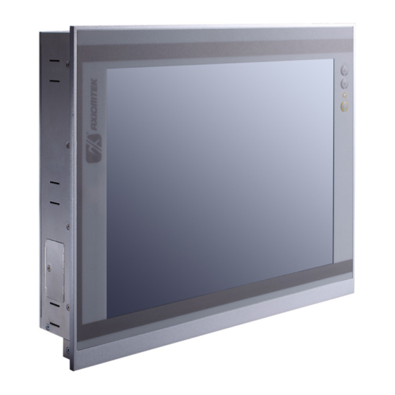
Package List General Description The GOT3156T-834 adopts a 15-inch XGA TFT LCD with 400nits brightness and an Intel® Processor E3827 (1M Cache, 1.75 GHz) to provide excellent computing performance and thermal resistance. This fanless platform is especially designed for operating under heavy-duty environment including steel refinery, oil pipe, machine maker operating systems and many more. -
Page 8: Specifications
GOT3156T-834 User’s Manual WLAN Antenna Supported (optional) GOT3156T-834 has 2 PCI Express Mini Card slots for optional add-on such as wireless LAN card for 802.11 a/b/g/n connections, 3G/GPRS application, and more. These slots also provide 3 optional fixed rotational WLAN/3G antennas for wireless network connection. - Page 9 GOT3156T-834 User’s Manual System Specification 15” XGA(1024x768) LCD with LED backlight 5-wire resistive touch Fanless Heat Dispensing Design IP65 front bezel Disk drive housing: 1 x 2.5” SATA drive Net Weight 4.2 Kgs ...
-
Page 10: Dimensions And Outlines
GOT3156T-834 User’s Manual Dimensions and Outlines The following diagrams show the dimensions and outlines of GOT3156T-834 Outline dimension: 377.9 x 309.3 x 60.7mm Introduction... - Page 11 GOT3156T-834 User’s Manual Cut Out dimension: 368.8 x 300mm Introduction...
-
Page 12: I/O Outlets
GOT3156T-834 User’s Manual I/O Outlets Please refer to the following illustration for I/O locations of the GOT3156T-834. Front panel buttons: I/O connectors Function Function POWER SWITCH (ATX) COM 1 (RS-232/422/485) Power Input connector (phoenix type) COM 2 (RS-232/422/485) COM 4 (RS-232/422/485) -
Page 13: Packing List
Panel mount kit x 10 Screws for HDD x 4 SATA data cable x 1 SATA power cable x 1 If you can’t find the package or any items are missing, please contact Axiomtek distributors immediately. Introduction... - Page 14 GOT3156T-834 User’s Manual This page is intentionally left blank. Introduction...
-
Page 15: Hardware And Installation
GOT3156T-834 User’s Manual Chapter 2 Hardware and Installation The GOT3156T-834 provides rich I/O ports and flexible expansions for you to meet different demand, for example CFast™ card. The chapter will show you how to install the hardware. It includes: ... -
Page 16: Open
GOT3156T-834 User’s Manual Open back cover This section tells users how to open back cover. Please follow the steps below. Step 1 Unscrew 14 screws on the back cover. Please refer the photo below. Step 2 Remove the back cover. -
Page 17: Cfast Card Installation
GOT3156T-834 User’s Manual CFast card Installation The GOT3156T-834 provides one CFast slot for users to install CFast™ card. Please refer to the following instructions for installation: ™ Step 1 Unscrew a screw on the cover of CFast card slot on left side. -
Page 18: Jumper And Switch Setting
GOT3156T-834 User’s Manual Jumper and Switch Setting Jumpers and Connectors Layout Component Side Hardware and Installation... - Page 19 GOT3156T-834 User’s Manual Solder Side Hardware and Installation...
- Page 20 GOT3156T-834 User’s Manual Jumper Settings Jumper is a small component consisting of jumper clip and jumper pins. Install jumper clip on 2 jumper pins to close. And remove jumper clip from 2 jumper pins to open. The following illustration shows how to set up jumper.
- Page 21 GOT3156T-834 User’s Manual PCIe device & mSATA device selection (JP6) The default setting of JP6 is for PCIe mini-card. If you want to install mSATA card on your system, please remember to set this jumper to “2-3 close”. Function Setting...
- Page 22 GOT3156T-834 User’s Manual Connectors The connectors allow the CPU Board to connect with other parts of the system. Ensure that all connectors are in place and firmly attached. The following table lists the function of each connector on the SBC87834.
- Page 23 GOT3156T-834 User’s Manual LVDS connector: CN1 CN1 Pin Assignment Description Description LVDSA_DATAN0 LVDSB_DATAN2 LVDSA_DATAP0 LVDSB_DATAP2 DDC DATA DDC CLOCK LVDSA_DATAN1 LVDSA_DATAN3 LVDSB_DATAN3 LVDSA_DATAP1 LVDSB_DATAN0 LVDSA_DATAP3 LVDSB_DATAP3 LVDSB_DATAP0 LVDSA_DATAN2 LVDSA_CLKN LVDSB_CLKN LVDSA_DATAP2 LVDSB_DATAN1 LVDSA_CLKP LVDSB_CLKP LVDSB_DATAP1 Hardware and Installation...
- Page 24 GOT3156T-834 User’s Manual LVDS inverter connector: CN2 CN2 Pin Assignment Description Description Inverter ON-OFF +12V +12V Backlight control +12V TOUCH connector: CN3 CN3 Pin Assignment Description Sense HDD power connector: CN4 CN9 Pin Assignment Description +12V Hardware and Installation...
- Page 25 GOT3156T-834 User’s Manual FRONT PANEL pin header: CN6 CN6 Pin Assignment Description Description + 5V Beep BUZZER Beep PWBTN RESET SATA LED +3.3V SIM card connector: CN7 CN7 Pin Assignment Description Description UIM PWR UIM RST UIM VPP UIM CLK...
- Page 26 GOT3156T-834 User’s Manual Digital I/O pin header: CN10 CN10 Pin Assignment Description Description GPIO0 GPIO1 GPIO2 GPIO3 GPIO4 GPIO5 GPIO6 GPIO7 GPIO8 GPIO9 GPIO10 GPIO11 GPIO12 GPIO13 GPIO14 GPIO15 Speaker-out & MIC-in connector: CN11 CN11 Pin Assignment Description Description SPKOUT_L-...
- Page 27 GOT3156T-834 User’s Manual USB CONNECTOR (reserved): CN14/CN20 CN14/CN20 Pin Assignment Description Audio Lin In connector: CN15 CN15 Pin Assignment Description LINE IN L LIN IN R Power lamp connector: CN16 CN16 Pin Assignment Description Description Power (+5V) Power button connector: CN17...
- Page 28 GOT3156T-834 User’s Manual Panel control Keypad connector: CN19 CN19 Pin Assignment Description Panel ON/OFF Normal indicate LED POWER LED Blacklight down Blacklight up USB box header: USB1 USB1 Pin Assignment Description Description USB- USB- USB+ USB+ Serial Port box header: COM3, COM4...
-
Page 29: Ethernet
RI, Ring Indicator Ethernet The GOT3156T-834 is equipped with a high performance Plug and Play Ethernet interface, full compliant with IEEE 802.3 standard, and can be connected with a RJ-45 LAN connector. Please refer to detailed pin assignment list below:... -
Page 30: Mountings: Panel / Wall / Desktop / Vesa
GOT3156T-834 User’s Manual Mountings: Panel / Wall / Desktop / VESA There are 4 application options for the GOT3156T-834, Panel/Wall/Desktop/VESA mountings. VESA-ARM/Wall-Mount VESA mount: 100x100 mm. Screw four screws to fix VESA arm or other VESA fixture. Wall mount: This is an optional wall kit. Screw it on the rear of chassis to support wall mount. - Page 31 GOT3156T-834 User’s Manual Panel-mount Kit Assembly The GOT3156T-834 is designed for panel mount application. To mount the GOT3156T-834, the standard set of mounting kit (included in the system packaging) is needed. Hardware and Installation...
-
Page 32: Hdd Installation
GOT3156T-834 User’s Manual HDD Installation The GOT3156T-834 provides a convenient Hard Disk Drive (HDD) bracket for users to install 2.5” SATA HDD. Please follow the steps: Step 1 Refer section 2.1 to open the back cover. Step 2 Unscrew 4 screws to take off the HDD bracket. - Page 33 GOT3156T-834 User’s Manual Step 4 Fix the HDD bracket into the system, and plug the data and power cable to HDD & SBC87834 mother board. Installation completed. Hardware and Installation...
-
Page 34: Dram Installation
GOT3156T-834 User’s Manual DRAM Installation The GOT3156T-834 provides one 204-pin DDR3L SODIMM socket that supports system memory up to 8GB. Please follow steps below to install the memory modules: Step 1 Refer to section 2.2 to open the back cover. -
Page 35: Msata Card Installation
GOT3156T-834 User’s Manual mSATA Card Installation The GOT3156T-834 provides one Mini card slot for user to install one mSATA card. When installing it, please refer to the following instructions and illustration: Step 1 Refer to section 2.1 to open the back cover and find out mini-card slot (CN8) on mainboard. -
Page 36: Wireless Lan Card Installation
GOT3156T-834 User’s Manual Wireless LAN Card Installation The GOT3156T-834 provides one Mini card slot for user to install one wireless LAN card. When installing the wireless LAN card, refer to the following instructions and illustration: Step 1 Refer to section 2.1 to open the back cover and find out mini-card slot on mainboard. - Page 37 GOT3156T-834 User’s Manual Step 3 Find the Antenna cable and connect it on wireless LAN card. Step 4 Remove the antenna plug from the top of back cover, then Install the antenna on the antenna connector. NOTE: Please have the extended bracket when using half-size mini card.
-
Page 38: 2.10 Power Input
GOT3156T-834 User’s Manual 2.10 Power Input GOT3156T-834 equips with a phoenix type power connector. It adopts 9VDC to 36VDC. Please follow the signs on power connector to connect DC power source. -: Power negative +: Power positive G: Safety ground NOTE: The safety ground must be connected to ensure the unit working appropriately. -
Page 39: Ami Bios Setup Utility
GOT3156T-834 User’s Manual Chapter 3 AMI BIOS Setup Utility This chapter provides users with detailed description how to set up basic system configuration through the AMIBIOS8 BIOS setup utility. Navigation Keys The BIOS setup/utility uses a key-based navigation system called hot keys. Most of the BIOS setup utility hot keys can be used at any time during the setup navigation process. -
Page 40: Main Menu
GOT3156T-834 User’s Manual Main Menu System Time/Date Use this option to change the system time and date. Highlight System Time or System Date using the <Arrow> keys. Enter new values through the keyboard. Press the <Tab> key or the <Arrow> keys to move between fields. The date must be entered in MM/DD/YY format. The time is entered in HH:MM:SS format. -
Page 41: Advanced Menu
GOT3156T-834 User’s Manual Advanced Menu The Advanced menu allows users to set configuration of the CPU and other system devices. You can select any of the items in the left frame of the screen to go to the sub menus: ... - Page 42 GOT3156T-834 User’s Manual ACPI Settings You can use this screen to select options for the ACPI Configuration, and change the value of the selected option. A description of the selected item appears on the right side of the screen. ACPI Sleep State Allow you to select the Advanced Configuration and Power Interface (ACPI) state to be used for system suspend.
- Page 43 GOT3156T-834 User’s Manual NCT6106D Super IO Configuration Use this screen to select options for the Super IO Configuration, and change the value of the selected option Serial Port 1-4 configuration Serial port: This option used to enable or disable the serial port.
- Page 44 GOT3156T-834 User’s Manual Serial type: This option used to select RS232/422/485 function. AMI BIOS Setup Utility...
- Page 45 GOT3156T-834 User’s Manual NCT6106D H/W Monitor This screen shows the Hardware Health Configuration. AMI BIOS Setup Utility...
- Page 46 GOT3156T-834 User’s Manual CPU Configuration This screen shows the CPU Configuration and Intel virtualization technology enable/disable selected AMI BIOS Setup Utility...
- Page 47 GOT3156T-834 User’s Manual IDE Configuration You can use this screen to select options for the SATA Configuration, and change the value of the selected option. SATA Mode Use this item to choose the SATA operation mode. Here are the options for your selection, IDE Mode, AHCI Mode.
- Page 48 GOT3156T-834 User’s Manual LPSS & SCC Configuration You can select any of the items in the frame of the screen to change the OS, the default setting is Win 7. Please be informed to select the Windows 8.x when installing Win 8 or Win 8.1.
- Page 49 GOT3156T-834 User’s Manual Security Configuration - Intel TXE Configuration The Advanced menu allows users to update the TXE firmware. AMI BIOS Setup Utility...
-
Page 50: Chipset Menu
GOT3156T-834 User’s Manual Chipset Menu The Chipset menu allows users to change the advanced chipset settings. AMI BIOS Setup Utility... - Page 51 GOT3156T-834 User’s Manual North Bridge This screen shows the North Bridge memory information. South Bridge AMI BIOS Setup Utility...
- Page 52 GOT3156T-834 User’s Manual USB Configuration You can use this screen to select options for the USB Configuration, If USB3.0 function used, XHCI Mode must enable and EHCI must disable. **XHCI default is Auto. AMI BIOS Setup Utility...
-
Page 53: Security
GOT3156T-834 User’s Manual Security AMI BIOS Setup Utility... -
Page 54: Boot Menu
GOT3156T-834 User’s Manual Boot Menu The Boot menu allows users to change boot options of the system. You can select any of the items in the left frame of the screen to go to the sub menus: Setup Prompt Timeout Set the Timeout for wait press key to enter Setup Menu. -
Page 55: Save&Exit
GOT3156T-834 User’s Manual Save&Exit AMI BIOS Setup Utility... - Page 56 GOT3156T-834 User’s Manual This page is intentionally left blank. AMI BIOS Setup Utility...
-
Page 57: Chapter 4 Drivers Installation
GOT3156T-834 User’s Manual Chapter 4 Drivers Installation System GOT3156T-834 supports Windows 7(64bit), Windows 8/8.1, WES 7(64bit) and WE8S. To facilitate the installation of system driver, please carefully read the instructions in this chapter before start installing. 4.1.1 Win 7 (64bit) Insert Driver CD and select the “\Drivers”. -
Page 58: Win 8/8.X
GOT3156T-834 User’s Manual 4.1.2 Win 8/8.x Insert Driver CD and select the “\Drivers”. Select all files and follow the installing procedure. NOTE: If you set your system in “Hibernate mode” before you install “Step 2. Graphic” driver, the monitor can’t display when you awake your system. Reboot your system and the monitor will display. -
Page 59: Touch Screen
Active: 24.6mA / Idle Mode: 13.4mA 4.2.2 Driver Installation- Windows 7/8.x The GOT3156T-834 provides a touch screen driver that users can install it under the operating system Windows 7/8.x. To facilitate installation of the touch screen driver, you should read the instructions in this chapter carefully before you attempt installation. - Page 60 GOT3156T-834 User’s Manual Select the “Standard Calibrate” tab. Calibration: To adjust the display with touch panel, click “Calibration” and follow the calibrate point to do calibration; there are five points on screen for calibration. Press OK. Drivers Installation...
-
Page 61: Embedded O.s
GOT3156T-834 User’s Manual Embedded O.S. The GOT3156T-834 provides the WES 7 and WE8S Embedded. The O.S. is supported devices which are listed below. 4.3.1 WES 7 & WE8S Here are supported onboard devices: Onboard Multi I/O SATA HDD ... - Page 62 GOT3156T-834 User’s Manual This page is intentionally left blank. Drivers Installation...
Need help?
Do you have a question about the GOT3156T-834 and is the answer not in the manual?
Questions and answers