Table of Contents
Advertisement
Quick Links
Advertisement
Table of Contents

Subscribe to Our Youtube Channel
Related Manuals for Advantech PCI-1625U


Summary of Contents for Advantech PCI-1625U
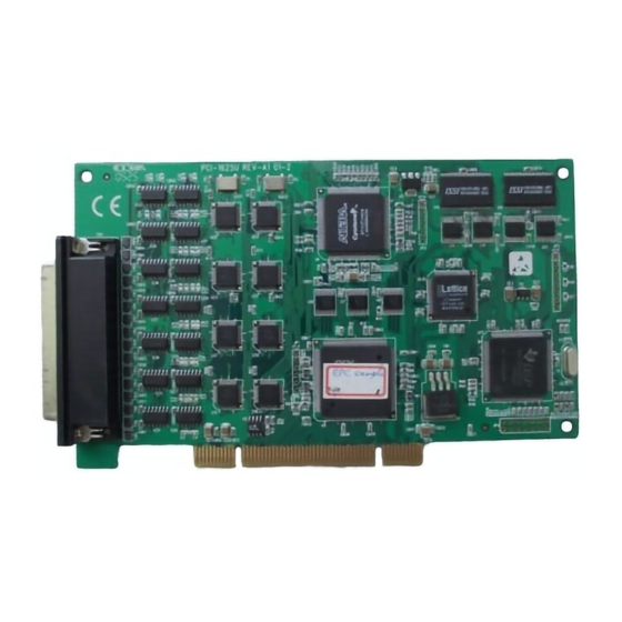
- Page 1 PCI-1625U 8-port Intelligent RS-232 Universal PCI Communication Card User Manual...
- Page 2 No part of this man- ual may be reproduced, copied, translated or transmitted in any form or by any means without the prior written permission of Advantech Co., Ltd. Information provided in this manual is intended to be accurate and reli- able.
- Page 3 Product Warranty (2 years) Advantech warrants to you, the original purchaser, that each of its prod- ucts will be free from defects in materials and workmanship for two years from the date of purchase. This warranty does not apply to any products which have been repaired or...
- Page 4 This product has passed the CE test for environmental specifications when shielded cables are used for external wiring. We recommend the use of shielded cables. This kind of cable is available from Advantech. Please contact your local supplier for ordering information.
- Page 5 If any item does not accord with the table, please contact your dealer immediately. • 1 x PCI-1625U • 1 x DB62 loopback for PCI-1625U • ICOM CD-ROM with Industrial Communication Driver, Utility and user manual...
- Page 6 PCI-1625U User Manual...
-
Page 7: Table Of Contents
Contents Chapter 1 Introduction ............. 2 Description ................ 2 Features ................3 Specifications ..............3 Ordering Information ............4 Chapter 2 Hardware Configuration ........ 6 Initial Inspection..............6 Card Installation ..............7 Chapter 3 Driver Setup and Installation....... 10 Introduction ..............10 Driver Setup .............. - Page 8 PCI-1625U with OPT8BP, OPT8C ......40 Table 5.3:PCI-1625U with OOPT8BP or OPT8C Male DB25 Pin Assignment ........40 5.1.4 PCI-1625U with OPT8H ..........41 Table 5.4:PCI-1625U with OPT8H male DB9 Pin As- signment ............41 5.1.5 PCI-1625U with OPT8FP ..........41 Wiring................42 Table 5.5:Terminal or PC (DTE) Connections ....
- Page 9 Introduction This chapter introduces PCI-1625U, its accessories and detailed specifications. Sections include: • Description • Features • Specifications • Ordering Information...
-
Page 10: Chapter 1 Introduction
PC. When you are transferring large amounts of data from multi- ple ports, servicing the interrupts alone consumes a large percentage of the capacity of your computer's CPU. PCI-1625U serves as a high speed, dedicated interrupt processor. The processor also has 1 MB of SRAM which can store serial data and reduce host CPU loading effectively. -
Page 11: Features
• Power Consumption: Typical 504 mA, Max 558 mA • Operating Temperature: 0~ 60° C (32~140° F) • Storage Temperature: -25 ~ 85° C (-13~185° F) • Operating Humidity: 5 ~ 95%, relative humidity, non-condensing Note: PCI-1625U does not support RAS service via crossover RS-232 Chapter 1... -
Page 12: Ordering Information
1.4 Ordering Information PCI Intelligent Communication Card • PCI-1625U: 8-port Intelligent RS-232 Universal PCI Comm. Card Accessories • OPT8AP: 8-Port RS-232 Connection Box/Female DB25 Connect (DCE) (1.5 m cable connectors with card and connection BOX included) • OPT8ASP: 8-Port RS-232 Connection Box/Female DB25 Connector w/ Surge protection(DCE) (1.5 m cable connectors with card and con-... - Page 13 Hardware Configuration This chapter shows how to get started with your PCI-1625U card. Sections include: • Initial Inspection • Card Installation...
-
Page 14: Chapter 2 Hardware Configuration
It should be free of marks and scratches and in perfect working order on receipt. As you unpack the PCI-1625U, check for signs of shipping damage (dam- aged box, scratches, dents, etc.). If it is damaged or it fails to meet speci- fications, notify our service department or your local sales representative immediately. -
Page 15: Card Installation
2.2 Card Installation Turn off your PC’s power supply whenever you install or remove the Intelligent PCI com- munication card or its cables. Static electricity can easily damage computer equipment. Ground yourself by touching the chassis of the computer (metal) before you touch any boards. - Page 16 PCI-1625U User Manual...
- Page 17 Driver Setup and Installation This chapter shows how to install, ver- ify and uninstall the driver. Sections include: • Introduction • Driver Setup • Verifying Driver Installation • Removing PCI ICOM Device • Driver Uninstallation...
-
Page 18: Chapter 3 Driver Setup And Installation
The PCI-1625U driver, however, will assign communication ports auto- matically. In order to fully utilize Windows 2000/XP advanced features such as multi-processing and multithreading, we offer pure 32-bit Win- dows 2000/XP device drivers for PCI-1625U cards. All these drivers con- form to Win32 COMM API standard. Note:... - Page 19 Steps for Windows 2000/XP Driver Setup Before you install the card into your system, we recommend you install the driver first. Please follow the steps below for the PCI-1625U Win- dows 2000/XP driver installation. Insert the companion CD-ROM disc into your CD-ROM drive.
- Page 20 Click the Continue button and the catalogue select page appears. Then click the Installation button for installation. Click ICOM Card Drivers for installation. PCI-1625U User Manual...
- Page 21 Choose the driver you want to install, then click the hyperlink. You.ll see the following screen. Click Next to continue installation. Chapter 3...
- Page 22 Type user name and company name, then click Next. Click Next to accept the default installation folder, or specify a folder by clicking the Browse button. PCI-1625U User Manual...
- Page 23 Confirm the program folder and click Next. Click Back to review or change your setting, or click Next to begin copying files. Chapter 3...
- Page 24 Click Finish to complete the installation. PCI-1625U User Manual...
-
Page 25: Verifying Driver Installation
3.3 Verifying Driver Installation After you have installed your card, go to Control Panel/System/Device Manager to look for the Device Name and COM port that are supposed to appear after you have installed the driver. Note: If your device has not been properly installed, there will be an exclamation mark (!) on the device name to indicate a conflicting device. - Page 26 On the General tab, you can see if the COM port works properly. If it does, you will see a message under the Device status box, stating, “This device is working properly”. The location shows what COM port is assigned to what port on the card, and helps configure the ports. PCI-1625U User Manual...
- Page 27 On the Settings tab, you can check relevant information for a specific port. On the figures below you can see which COM port is assigned to which port on the PCI slot. The tab also shows the card model name and FPGA version.
-
Page 28: Removing Pci Icom Series Device
Access Device Manager in the hardware tab system properties. Click the plus sign (+) on the right of the Ports (COM & LPT) device category to expand it. Select the specific “Advantech PCI communication port” you want to remove, and click the Uninstall button to remove the port you have selected. - Page 29 Click the plus sign (+) on the right of the Advantech ICOM Adapters device category to expand it, and select Advantech PCI- 1625U.
-
Page 30: Driver Uninstallation
Insert the ICOM CD and click the driver you want to uninstall. Choose the Modify radio button if you want to save another driver, or choose the Remove radio button to remove all installed compo- nents.. Click the Finish button to complete the uninstallation. PCI-1625U User Manual... - Page 31 ICOM Tools This chapter provides information on installation and usage of ICOM Tools. Sections include: • Introduction • Installation • User Interface of ICOM Tools...
-
Page 32: Chapter 4 Icom Tools
Chapter 4 ICOM Tools 4.1 Introduction Advantech ICOM Tools is a convenient utility that has been designed to help you test the performance of ICOM cards through analyzing the port status. It features an easy to use graphical user interface that will soon make you familiar with testing via menu commands and toolbar buttons. -
Page 33: User Interface Of Icom Tools
4.3 User Interface of ICOM Tools 4.3.1 Menu Bar On the Menu Bar you can select various menu commands to perform port-testing functions. You can also use the short-cut keys. Port Submenu Select: Select the ports you want to configure Setup: Setup the configuration of a specific port Close: Close a specific port Run: Run the test on a specific port... -
Page 34: Tool Bar
All Ports Setup: Sets up the configuration of all ports not running test All Ports Run: Runs test on all ports All Ports Stop: Stops test on all ports Clear Message: Clears messages on Message Logo area and the Rx length information on the Performance Listing area PCI-1625U User Manual... -
Page 35: Com Port Tab
4.3.3 Com Port Tab Each Com Port tab represents a specific port you have selected for test and configuration. On the tab, you can see the Transfer Mode, Port Sta- tus, and Message Logo area. Transfer Modes You can specify the transfer mode to be Normal, loopback (active) or loopback (passive). -
Page 36: Port Status
On the Message Logo area, you can see the relevant messages about the port(s) you have selected. For information about specific messages in this area, please refer to Sec- tion 4.5, Messages on the Status Bar and Message Logo area. PCI-1625U User Manual... -
Page 37: Tx Slide Bar
4.3.6 Tx Slide Bar The Tx Slide Bar allows you to control the overall system loading. You can adjust the transmission rate of your port(s) from 0% to 100%. Just drag the slide button along the track to adjust the transmission rate. 4.3.7 Performance Listing Area On the performance listing area, you can see the relevant information, such as Rx Length (received packet byte length), Bytes/Sec (transmission... -
Page 38: Using The Icom Tools Utility
Launch ICOM Tools. You will first see the Program Window such as Figure 4.1. Since you haven’t selected any port for testing yet, all you can see now is a blank window area. Figure 4.1: ICOM Tools program window PCI-1625U User Manual... -
Page 39: Figure 4.2:Select Port Dialog Box
Select the port(s) you want to test by the Port/Select menu com- mand or by clicking the Port Select button on the Toolbar, and a dialog box such as Fig. 2 will appear. Figure 4.2: Select Port dialog box Select the port(s) you want to perform test on from the checkboxes next to each COM port. -
Page 40: Figure 4.4:Icom Tools User Interface
Port/Setup menu command (or if you want to configure all ports at once, just click the All Ports Setup button or access the All Ports/Setup menu command) to bring up the Configure Port dialog box such as below. PCI-1625U User Manual... -
Page 41: Figure 4.5:Test Information On The Performance Listing Area
In the Configure Port dialog box, you can configure the Baud Rate, Data bits, Parity, Stop Bits and the flow control mode for that specific port (or for all ports). After you have configured all the settings you want to change, click OKto make this configuration active. -
Page 42: Close Port
Close button or access Port/Close menu command to close the port. 4.4.4 Exit the ICOM Tools utility To exit the ICOM Tools utility, simply access Port/Exit menu command or click the Close button on the upper right corner of the program win- dow. PCI-1625U User Manual... -
Page 43: Messages On Status Bar And Message Logo Area
4.5 Messages on Status Bar and Message Logo Area Messages appearing on the Status Bar and Message Logo area are helpful in understanding specific information of your system settings and perfor- mance. 4.5.1 Status Bar Messages BUSY: the port is currently used by another application. FAIL: the configuration parameters are not accepted by the port N/A PORT: the port is not available in the system READY: the port is ready to run or to be configured. -
Page 44: Message Logo Messages
LB Error - %d: data error is detected in loop back LB Rx Pending: Loop back mode is waiting for incoming data Data Setup Error: parameter error in port configuration PCI-1625U User Manual... - Page 45 Pin Assignments & Wiring This chapter shows how the different pins are assigned and how to wire PCI- 1625U. Sections include: • Pin Assignments • Wiring...
-
Page 46: Figure 5.1:Pci-1625U Rs-232 Mode Db62 Pin Assign Ment
Chapter 5 Pin Assignments & Wiring 5.1 Pin Assignments 5.1.1 PCI-1625U The following diagram shows the pin assignments for the PCI-1625U card's DB-62 connectors for RS-232. Figure 5.1: PCI-1625U RS-232 Mode DB62 Pin Assignment PCI-1625U User Manual... -
Page 47: Table 5.1:Pci-1625U Rs-232 Mode Db62 Pin Descrip Tion
Table 5.1: PCI-1625U RS-232 Mode DB62 Pin Description Pin no. Signal Pin no. Signal Pin no. Signal TxD0 RxD0 CTS0 DTR0 DSR0 RTS0 DCD0 RxD1 TxD1 CTS1 DSR1 DTR1 RTS1 DCD1 TxD2 RxD2 CTS2 DTR2 DSR2 RTS2 DCD2 RxD3 TxD3... -
Page 48: Pci-1625U With Opt8Ap
5.1.2 PCI-1625U with OPT8AP If you choose accessory OPT8AP to connect with PCI-1625U, the female DB25 connectors of OPT8AP are as shown below. Table 5.2: PCI-1625U with OPT8AP Female DB25 Pin Assignment Signal 5.1.3 PCI-1625U with OPT8BP, OPT8C If you choose accessory OPT8BP and OPT8C connects with PCI-1625U, male DB25 connectors of OPT8BP and OPT8C are as shown below. -
Page 49: Pci-1625U With Opt8H
5.1.4 PCI-1625U with OPT8H If you choose accessory Opt8H to connect with PCI-1625U, male DB9 connectors of OPT8H are as shown below. Table 5.4: PCI-1625U with OPT8H male DB9 Pin Assignment Signal 5.1.5 PCI-1625U with OPT8FP If you choose accessory Opt8FP to connect with PCI-1625U, you could access RS-422 device through OPT8FP and female DB25 connectors of OPT8FP are shown as below. -
Page 50: Table 5.5:Terminal Or Pc (Dte) Connections
In some situations, you may be able to get by with just three lines: data on RxD, TxD and ground. Table 5.5: Terminal or PC (DTE) Connections DB25 Male DB25 Male or Female: Terminal Signal Signal PCI-1625U User Manual... -
Page 51: Table 5.6:Modem Connections
Table 5.6: Modem Connections DB25 Male Modem (DCE) Signal Signal For DTE to DCE connections, use straight-through cable (i.e., you don't have to reverse lines 2 and 3, lines 4 and 5, and lines 6 and 20 since, in general, the DCE RS-232 interfaces are reversed themselves). Table 5.7: Terminal without Handshake DB-25 Male Terminal, PC (DTE) - Page 52 PCI-1625U User Manual...
Need help?
Do you have a question about the PCI-1625U and is the answer not in the manual?
Questions and answers