
Subscribe to Our Youtube Channel
Related Manuals for Gefen EXT-DVI-2500HD


Summary of Contents for Gefen EXT-DVI-2500HD
- Page 1 ® DVI 2500HD Optical DVI Dual Link Extension EXT-DVI-2500HD User Manual www.gefen.com...
- Page 3 Chatsworth, CA 91311 www.gefen.com support@gefen.com Notice Gefen, LLC reserves the right to make changes in the hardware, packaging and any accompanying documentation without prior written notice. DVI•2500HD is a trademark of Gefen, LLC. © 2013 Gefen, LLC. All Rights Reserved All trademarks are the property of their respective owners.
-
Page 4: Table Of Contents
CONTENTS Introduction Operation Notes Features Sender Panel Layout Sender Panel Descriptions Receiver Panel Layout Receiver Panel Descriptions Connecting And Operating The DVI•2500HD Connecting The DVI•2500HD In Direct DDC Mode 10 Connecting The DVI•2500HD In Virtual DDC Mode 11 Connecting The DVI•2500HD In Virtual DDC Mode 12 Specifications 13 Warranty... -
Page 5: Introduction
Congratulations on your purchase of the DVI•2500HD. Your complete satisfaction is very important to us. Gefen Gefen delivers innovative, progressive computer and electronics add-on solutions that harness integration, extension, distribution and conversion technologies. Gefen’s reliable, plug-and-play products supplement cross-platform computer systems, professional audio/video environments and HDTV systems of all sizes with hard-working solutions that are easy to implement and simple to operate. -
Page 6: Operation Notes
OPERATION NOTES READ THESE NOTES BEFORE INSTALLING OR OPERATING THE DVI•2500HD • LC terminated fiber optic cables (up to 2 pairs) are required for operation of the DVI•2500HD system. A single CAT-5e cable will also be required when operating in Direct DDC mode only. •... -
Page 7: Features
FEATURES Features • Extends any dual link DVI compliant device up to 6,600 feet (2 km) from the computer • Uses a 4 strand multimode LC-LC fiber optic cable; 2-strand/1-strand (duplex) for Single-Link • Optionally use one CAT-5e cable for DDC and control signals •... -
Page 8: Sender Panel Layout
SENDER PANEL LAYOUT Front Panel Back Panel... -
Page 9: Sender Panel Descriptions
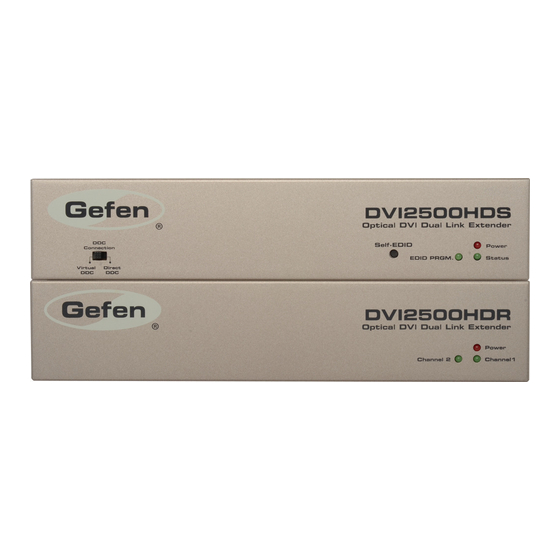
SENDER PANEL DESCRIPTIONS LED Power Indicator This LED will become active once the included 5V DC power supply is properly connected between the sender and an open wall power socket. EDID Mode Selector Switch This switch will set either the Direct DDC or Virtual DDC modes. For a description of these modes please see page 8. -
Page 10: Receiver Panel Layout
RECEIVER PANEL LAYOUT Front Panel Back Panel... -
Page 11: Receiver Panel Descriptions
RECEIVER PANEL DESCRIPTIONS LED Power Indicator This LED will become active once the included 5V DC power supply is properly connected between the sender and an open wall power socket. Channel 2 LED Link Indicator This LED will become active once a link for Channel 2 has been established between the sending and receiving units. -
Page 12: Connecting And Operating The Dvi•2500Hd
CONNECTING AND OPERATING THE DVI•2500HD DDC Modes DVI•2500HD can operate in 2 DDC modes. It is important to determine the DDC mode before attempting to connect anything to the DVI•2500HD units. The DDC will carry EDID information which is critical in determining a connected device’s resolution capabilities and operational limits. -
Page 13: Connecting The Dvi•2500Hd In Direct Ddc Mode
CONNECTING THE DVI•2500HD IN DDC MODE Locate the DDC Mode switch on the front panel of the DVI•2500HD Sending unit. Ensure that the switch is set to Direct DDC. Connect a DVI cable (one is supplied) between the DVI source device’s DVI output and the DVI•2500HD Sending unit’s DVI input. -
Page 14: Connecting The Dvi•2500Hd In Virtual Ddc Mode
CONNECTING THE DVI•2500HD IN VIRTUAL DDC MODE Locate the DDC Mode switch on the front panel of the DVI•2500HD Sending unit. Ensure that the switch is set to Virtual DDC. Record the DVI-capable output device’s (i.e. DVI display) EDID into the DVI•2500HD Sending unit. - Page 15 CONNECTING THE DVI•2500HD IN VIRTUAL DDC MODE Connect a DVI cable between the DVI•2500HD Receiving unit’s DVI output and the DVI-capable output device’s (i.e. DVI display) DVI input. Connect both of the included 12V DC power supplies between the Sending and Receiving units and open wall power sockets.
-
Page 16: Specifications
SPECIFICATIONS Video Amplifier Bandwidth ..............2 x 165 MHz Input Video Signal ................1.2 Volts p-p Input DDC Signal ................. 5 Volts p-p (TTL) DVI Connector ..............DVI-D (24 pin) Female Video Link Connector ..................LC DDC Link Connector ..............RJ-45 Shielded Power Supply .................... -
Page 17: Warranty
If equipment fails because of such defects and Gefen is notified within two (2) years from the date of shipment, Gefen will, at its option, repair or replace the equipment, provided that the equipment has not been subjected to mechanical, electrical, or other abuse or modifications. - Page 20 Rev A7 20600 Nordhoff St., Chatsworth CA 91311 1-800-545-6900 818-772-9100 fax: 818-772-9120 www.gefen.com support@gefen.com This product uses UL listed or CE compliant power supplies.
Need help?
Do you have a question about the EXT-DVI-2500HD and is the answer not in the manual?
Questions and answers