Table of Contents
Advertisement
Quick Links
Download this manual
See also:
User Manual
Globalsat Technology Corporation
16F., No. 186, Jian-Yi Road, Chung-Ho City, Taipei Hsien 235, Taiwan
Tel: 886.2.8226.3799/ Fax: 886.2.8226.3899
service@globalsat.com.tw
www.globalsat.com.tw
AVL Tracking System
TR-600
V 1.2
USGlobalSat Incorporated
14740 Yorba Court , Chino, CA 91710
Tel: 888.323.8720 /Fax: 909.597.8532
sales@usglobalsat.com
www.usglobalsat.com
Advertisement
Table of Contents

Subscribe to Our Youtube Channel
Related Manuals for Globalsat TR-600


Summary of Contents for Globalsat TR-600
- Page 1 AVL Tracking System TR-600 V 1.2 Globalsat Technology Corporation USGlobalSat Incorporated 16F., No. 186, Jian-Yi Road, Chung-Ho City, Taipei Hsien 235, Taiwan 14740 Yorba Court , Chino, CA 91710 Tel: 886.2.8226.3799/ Fax: 886.2.8226.3899 Tel: 888.323.8720 /Fax: 909.597.8532 service@globalsat.com.tw sales@usglobalsat.com www.globalsat.com.tw...
-
Page 2: Table Of Contents
CONTENT 1. Introduction ............................3 1.1 Introduction ..........................3 1.2 Features ............................ 3 1.3 Hardware Architecture ......................4 1.4 Hardware specification ......................5 1.5 Appearance ..........................6 1.6 LED indicator ........................... 7 1.7 Cable description ........................8 1.8 Accessories ..........................10 2 Operation ............................ -
Page 3: Introduction
The TR-600 has a solid and rigid housing, for simple installation. It provides real-time GPS positions anytime and anywhere with an open view to the sky, and offers precise positioning, and reports vehicle status to the server with necessary information shown on the map. -
Page 4: Hardware Architecture
1.3 Hardware Architecture GPS antenna GSM antenna Speaker MODEM Microphone USART/ RS-232 Analog Motion Li backup Digital Digital Input Sensor Battery input output... -
Page 5: Hardware Specification
1.4 Hardware specification Item Description Dimension 98 mm X 65 mm X 22 mm High performance line ARM-base 32-bit MCU GPS receiver SiRF Star III high performance GPS chipset -30℃ ~ + 80℃ Temperature Operation -40℃ ~ + 85℃ Storage GPS Antenna SMA Type connector Active antenna ( 3.3~3.8V) -
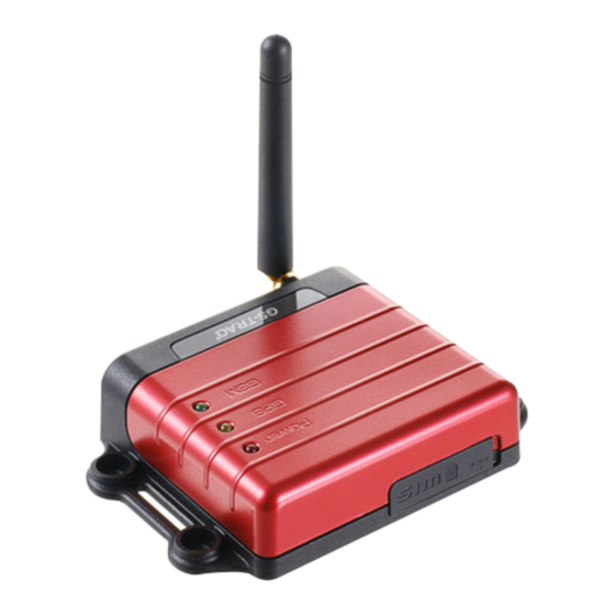
Page 6: Appearance
1.5 Appearance Peripheral interface port I/O port Power Status LED GPS LED GSM LED For fixing device with screws GSM antenna connector For fixing device with belt GPS antenna connector SIM card holder... -
Page 7: Led Indicator
GPS not fix GPS fix GSM LED (Green) Permanently off Fast blinking (Once Slow blinking (Once every 1 second) every 3 seconds) State GSM off TR-600 is TR-600 is registered searching GSM full service network SIM card is registering to GSM network... -
Page 8: Cable Description
1.7 Cable description 14 Pin I/O Cable Wire Color Description Green/ White Analog Input_1 White Digital Output 3 (Negative Trigger) Gray Digital Output 1 (Negative Trigger) Purple Digital Input 3 (Positive Trigger) Blue Digital Input 1 (Negative Trigger) Black Ground Main Power Green Digital Output 2 (Negative Trigger) - Page 9 8 Pin Cable Wire Color Description Pink Audio_5V Blue Speaker 1(Positive) Serial-1_5V White Receiver 1 White Microphone 1 P Black (3 Pieces) Ground Orange Speaker 1(Negative) Green Transmission 1...
-
Page 10: Accessories
1.8 Accessories Main Unit GPS Antenna GSM Antenna 14 Pin I/O Cable 8 Pin Cable RS-232 Cable (Option) -
Page 11: Operation
To eject SIM card, simply, use your finger nail and apply slight pressure. Note: Make sure to disable the SIM PIN entry function on the SIM card before inserting your SIM card Note: Before installing or taking out the SIM card, please power off the TR-600. -
Page 12: Install The Gps And Gsm Antenna
2.2 Install the GPS and GSM antenna Install the GSM antenna to the GSM antenna port on the left side of the back of the device and install the GPS antenna to the GPS antenna port on the right side of the back of the device making sure both antennas tightly screwed in place. -
Page 13: Installing The Emergency Button
2.3 Installing the Emergency button There is a line of the 14 pin IO cable for connecting push button for emergency help. One end of the button must be connected to the SOS line and the other end must be connected to the ground line.
Need help?
Do you have a question about the TR-600 and is the answer not in the manual?
Questions and answers