Bosch PLENA matrix Operation Manual
Public address system
Hide thumbs
Also See for PLENA matrix:
- Operating manual (192 pages) ,
- Installation and operation manual (162 pages) ,
- Installation and user instructions manual (124 pages)
Table of Contents
Advertisement
Advertisement
Table of Contents

Related Manuals for Bosch PLENA matrix


Summary of Contents for Bosch PLENA matrix
- Page 1 PLENA matrix Public Address system Operation manual...
-
Page 3: Table Of Contents
Adjust the audio output volume level Multi Channel DSP Amplifier 8.4.1 Activate the active override audio input function 8.4.2 Activate the amplifier auto standby 8.4.3 Operate the amplifier with the PC GUI DSP Matrix Mixer Bosch Security Systems B.V. Operation manual 2013-06 | V1.0 |... -
Page 4: En | Table Of Contents Plena Matrix
Multi Channel DSP Amplifier 11.2.3 Call Station 11.2.4 Wall Control Panel 11.3 Environmental conditions 11.3.1 DSP Matrix Mixer 11.3.2 Multi Channel DSP Amplifier 11.3.3 Call Station 11.3.4 Wall Control Panel 11.4 Standards 2013-06 | V1.0 | Operation manual Bosch Security Systems B.V. -
Page 5: Safety
The user may find the following booklet prepared by the Federal Communications Commission helpful: “How to identify and Resolve Radio-TV Interference Problems”. This booklet is available from the U. S. Government Printing Office, Washington, DC 20402, Stock No. 004-000-00345-4. Bosch Security Systems B.V. Operation manual 2013-06 | V1.0 |... - Page 6 PLENA matrix Warning! This is a Class A product. In a domestic environment this product may cause radio interference in which case the user may be required to take adequate measures. 2013-06 | V1.0 | Operation manual Bosch Security Systems B.V.
-
Page 7: About This Manual
This manual is available as a digital document in the Adobe Portable Document Format (PDF). Refer to the product related information on www.boschsecurity.com. Intended audience This manual is intended for installers, operators and users of a PLENA matrix public address system. Alerts and notice signs Four types of signs can be used in this manual. -
Page 8: Document History
| About this manual PLENA matrix Document history Release date Documentation version Reason 2013.06.18 V1.0 – Edition. 2013-06 | V1.0 | Operation manual Bosch Security Systems B.V. -
Page 9: System Overview
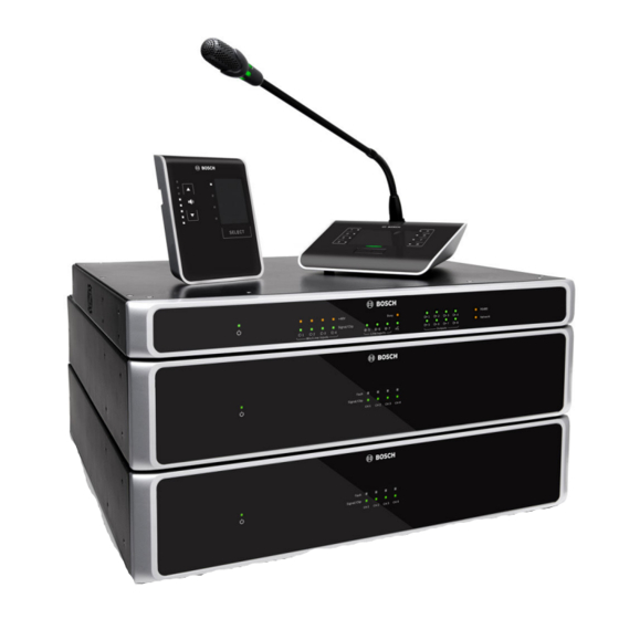
– PLM-8M8 – 8 Channel DSP Matrix Mixer: The digital signal processor (DSP) Matrix Mixer is the heart of the PLENA matrix system. When combined with the Call Station (PLM‑8CS) and the Wall Control Panel (PLM‑WCP) making announcements and controlling individual zones is easy. The multi channel DSP amplifiers (PLM‑4Px2x) can be connected via STP type CAT‑5 (Amp Link) or via phoenix terminal... - Page 10 The PC GUI offers a configuration page and user operation page to setup and control the PLM‑8M8 DSP Matrix Mixer and also the PLM‑4Px2x Amplifiers. The software GUIs are able to be downloaded from the Bosch website: www.boschsecurity.com. 2013-06 | V1.0 | Operation manual Bosch Security Systems B.V.
-
Page 11: Application Area
System overview | en Application area The PLENA matrix product range is designed to be used in small to medium‑sized public address application areas, such as; hotels, shops, supermarkets, restaurants, bars, canteens, gyms, showrooms, regional airports, warehouses, educational facilities, theatres-back of house, and other places where announcements and background music (BGM) creates the right atmosphere. -
Page 12: Planning
Sufficient free space and access at the rear of the 19" units for connectors and wiring. – Check you have downloaded the latest versions of documentation and software from the Bosch website: www.boschsecurity.com. 2013-06 | V1.0 | Operation manual Bosch Security Systems B.V. -
Page 13: Installation
Notice! If you install the product into a 19” rack: - Ensure that it does not exceed the overheating temperature (+45°C ambient). - Use the included Bosch 19” mounting brackets. Bosch Security Systems B.V. Operation manual 2013-06 | V1.0 |... -
Page 14: Call Station
500m. This may be extended with the use of better cable and less call stations on that cable run. If the cables are exposed; use black CAT‑5 cables. This makes for a better visual look once installed, as it matched the black of the call station. 2013-06 | V1.0 | Operation manual Bosch Security Systems B.V. -
Page 15: Wall Control Panel
500m. This may be extended with the use of better cable and less wall control panels on that cable run. If the cables are exposed; use black or white CAT‑5 cables. This makes for a better visual look once installed. Bosch Security Systems B.V. Operation manual 2013-06 | V1.0 |... -
Page 16: Pc Gui Software
Configuration of the DSP matrix mixer / system (inputs, outputs, settings and controls) is done by the PLENA matrix graphical user interface (GUI) PC software. Use the Amplifier PC software GUI, when configuring the multi channel DSP amplifier. It is important to always use the most up‑to‑date version of the PC GUI. -
Page 17: Ios Gui Software
Notice! To use the iOS GUI app will require the connection and configuration of a wireless router. Please refer to the manual supplied with the wireless router for appropriate configuration. Bosch Security Systems B.V. Operation manual 2013-06 | V1.0 |... -
Page 18: Connections
Do NOT use a RJ45 cable boot of sleeve when terminating these cables. Using such items may result in the cables not fitting into the device or the bend radius of the UTP to be exceeded. 2013-06 | V1.0 | Operation manual Bosch Security Systems B.V. -
Page 19: Multi Channel Dsp Amplifier
For best practice Bosch recommends use with STP CAT‑5 (e) cable. – Maximum recommended cable distance 5m. Auto Standby – 4‑pole Phoenix connector to attach a Bosch motion sensor, to activate auto Mode standby. connections – The amplifier also can supply 12V DC power for a motion detector. - Page 20 The 12V DC power output (Auto Standby) connection should be only connected with products in accordance with recommendations outlined in this manual. Notice! Recommended motion sensors for use with the auto standby mode are the Bosch range of sensors. For more information regarding Bosch security products contact your local Bosch Security certified partner or go to www.boschsecurity.com for details.
-
Page 21: Dsp Matrix Mixer
Audio line level analog override input (+, - and shield balanced input). Network – RJ45 Ethernet communication socket: – Communication with the PLENA matrix GUI applications. Wall control – RJ45 socket for RS485 data communication, power and audio bus: panel –... - Page 22 | Connections PLENA matrix Notice! Hardware settings cannot be overruled or changed by the PC GUI application software. See also – DSP Matrix Mixer and Amplifiers, page 13 2013-06 | V1.0 | Operation manual Bosch Security Systems B.V.
-
Page 23: Configuration
A DIP switch in the down position is OFF. A DIP switch in the up position is ON. Eg. Down – Up - Down will equal call station ID number 3 in the table above. Bosch Security Systems B.V. Operation manual 2013-06 | V1.0 |... -
Page 24: Wall Control Panel Dip Switch Settings
If all DIP Switches are down/OFF this is ID 1 (Factory default). If all DIP switches are up/ON this is ID 16. Notice! Hardware settings cannot be overruled or changed by the GUI application software. 2013-06 | V1.0 | Operation manual Bosch Security Systems B.V. -
Page 25: Multi Channel Dsp Amplifier Settings
Switch 3: Input Sensitivity Channel Y: 6.15V (UP) / 1.22V (DOWN) input sensitivity. Default: DOWN. Notice! Hardware settings cannot be overruled or changed by the GUI configuration software. See also – DSP matrix mixer PC GUI, page 26 Bosch Security Systems B.V. Operation manual 2013-06 | V1.0 |... -
Page 26: Dsp Matrix Mixer Pc Gui
To change the unit from DHCP to a static IP configuration, follow the procedure above to open the connect to target window. Once in the unit is selected, you can change: 2013-06 | V1.0 | Operation manual Bosch Security Systems B.V. - Page 27 Selection of the Line inputs and level control; per zone. – Master level control; per zone. – Call station input level control; per zone. – Soft standby. – Global mute. – Connect to device. Bosch Security Systems B.V. Operation manual 2013-06 | V1.0 |...
-
Page 28: Multi Channel Dsp Amplifier Pc Gui
Refer to PC GUI software, page 16 installation to install the PC GUI, if needed. Proceed as follows: Notice! Changes and updates to this procedure are available in the software down load file. 2013-06 | V1.0 | Operation manual Bosch Security Systems B.V. - Page 29 PC GUI operation document in the help menu of the PC GUI. Refer to DSP matrix mixer PC GUI, page 26 when use the amplifier connected to the DSP matrix mixer. Bosch Security Systems B.V. Operation manual 2013-06 | V1.0 |...
- Page 30 Input mixer. – Crossover. – Parametric EQ – including Bass Enhancement on/off. – Delay. – DRC – Dynamic Range Compression. – Output Level control. See also – Troubleshooting, page 41 2013-06 | V1.0 | Operation manual Bosch Security Systems B.V.
-
Page 31: Amplifier Bridging Configuration
Be sure that the higher voltage does not create a problem for the speakers used: If any problem exists, this may be solved with the use of a 2:1 step down transformer Bosch Security Systems B.V. Operation manual 2013-06 | V1.0 |... -
Page 32: Operation
Continue with one of the following chapters: – Call Station, page 33 – Wall Control Panel, page 35 – Multi Channel DSP Amplifier, page 37 – DSP Matrix Mixer, page 39 2013-06 | V1.0 | Operation manual Bosch Security Systems B.V. -
Page 33: Call Station
Green: Ready. The call station microphone is active, you may talk. PTT button – Press‑to‑talk (paging call) button. Keep button pushed down to continue to talk. Continue with: – Pre-settings and selections, page 34 – Making an announcement, page 34 Bosch Security Systems B.V. Operation manual 2013-06 | V1.0 |... -
Page 34: Pre-Settings And Selections
A good rule when making an announcement through the call station is to keep at least one hands distance away from the microphone. This will reduce popping noises and distortion in the system. 2013-06 | V1.0 | Operation manual Bosch Security Systems B.V. -
Page 35: Wall Control Panel
Capacitive button to toggle through the connected line input sources (1, 2, 3 or off) selection button or mic./line (1, 2, 3 or 4) input source. Continue with: – Select the input source, page 36 – Adjust the audio output volume level, page 36 Bosch Security Systems B.V. Operation manual 2013-06 | V1.0 |... -
Page 36: Select The Input Source
The level will increase or decrease 3dB for every button press of the arrows, and the LED is 6dB per step. Therefore it will sometimes require 2 pushes to see the next LED illuminate. 2013-06 | V1.0 | Operation manual Bosch Security Systems B.V. -
Page 37: Multi Channel Dsp Amplifier
Refer to Multi Channel DSP Amplifier PC GUI, page 28; for DSP features. Notice! Hardware settings (controls and switches) cannot be overruled or changed by the DSP matrix mixer and amplifier PC GUI configuration software. Bosch Security Systems B.V. Operation manual 2013-06 | V1.0 |... -
Page 38: Activate The Active Override Audio Input Function
“wakes up” and restore and return to its prior configuration immediately. Notice! The recommended sensor to be used, and can be powered by the amplifier, is the Bosch PIR range of detectors. Refer to www.boschsecurity.com. 8.4.3 Operate the amplifier with the PC GUI Operating and configuration of the DSP features can only be used via the amplifier PC GUI. -
Page 39: Dsp Matrix Mixer
Operation | en DSP Matrix Mixer The DSP matrix mixer; the brains of the PLENA matrix system. It has no external controls on the unit itself. To control this unit it requires either connection to the call station and /or wall control panel, or a online connection to the PC GUI. -
Page 40: Activate The Override Input Function
Operating and configuration of the DSP features can only be used via the DSP matrix mixer PC GUI. Refer to DSP matrix mixer PC GUI, page 26. Operation instructions are available within the help of the PC GUI. 2013-06 | V1.0 | Operation manual Bosch Security Systems B.V. -
Page 41: Troubleshooting
Amplifier: Fault light – Indicates a fault with – Send immediately for constantly ON ( Red). that amplifier channel. service and/or contact the Bosch authorized dealer or installer for assistance. Bosch Security Systems B.V. Operation manual 2013-06 | V1.0 |... - Page 42 Check that the CAT‑5 cable is not damaged in anyway. – Download and connect with the latest version of PC GUI and check the RS485 status "Device > RS486 device status". 2013-06 | V1.0 | Operation manual Bosch Security Systems B.V.
- Page 43 – Unit(s) and/or router are check cabling is correctly not on. connected, check that – PC is not connected to the PC is connected to network. the network. Bosch Security Systems B.V. Operation manual 2013-06 | V1.0 |...
-
Page 44: Customer Service
| Troubleshooting PLENA matrix Customer service If a fault cannot be resolved, please contact your supplier or system integrator, or go directly to your Bosch representative. 2013-06 | V1.0 | Operation manual Bosch Security Systems B.V. -
Page 45: Maintenance
PLENA matrix Maintenance | en Maintenance The PLENA matrix system has been designed to operate without problems for a long period of time, with a minimum of maintenance. In order to guarantee trouble-free operation: – Clean the units, page 45 –... -
Page 46: Technical Data
BGM inputs Input clip (Pad on) 10.2 dBu (8 dBV) <0.004 % Dynamic range (A‑weighted) >103 dB Connectors 3x pair of Cinch RCA Outputs Output level 17.7 dBu (15.5 dBV) 2013-06 | V1.0 | Operation manual Bosch Security Systems B.V. -
Page 47: Multi Channel Dsp Amplifier
100 V / 70 V / 8 ohm / 4 ohm Rated output power per channel (continous *): – PLM‑4P125 130 W – PLM‑4P220 220 W Rated output power per channel (burst *): Bosch Security Systems B.V. Operation manual 2013-06 | V1.0 |... - Page 48 4x 3‑pole Phoenix terminal (Metric) – Logic and standby overide 2‑pole Phoenix terminal (Metric) Ethernet Network 10/100 Mbps RJ45 12 V output power for motion sensor 2‑pole Phoenix terminal (Metric) 2013-06 | V1.0 | Operation manual Bosch Security Systems B.V.
-
Page 49: Call Station
24.4 dBu (22.2 dBV) Connectors RS485 loop‑through RJ45 11.1.4 Wall Control Panel Power supply (supplied by PLM‑8M8) Voltage range 30 ‑ 50 VDC Power consumption 0.5 W Connectors RS485 loop‑through RJ45 Bosch Security Systems B.V. Operation manual 2013-06 | V1.0 |... -
Page 50: Mechanical
50 x 156 x 140 mm (2 x 6.1 x 25.5 in) Microphone stem length 390 mm (15.35 In) Color Trafic black (RAL 9017) Silver (RAL 9006) Weight Approx. 0.77 kg Approx. 1.69 lb 2013-06 | V1.0 | Operation manual Bosch Security Systems B.V. -
Page 51: Wall Control Panel
130 x 100 x 30 mm 5.1 x 3.9 x 1.2 in Mounting Surface mount bracket Color Trafic black (RAL 9017) Silver (RAL 9006) Weight Approx. 0.13 kg Approx. 0.29 lb Bosch Security Systems B.V. Operation manual 2013-06 | V1.0 |... -
Page 52: Environmental Conditions
Wall Control Panel Operating temperature -10 ºC to +45 ºC Storage temperature -40 ºC to +70 ºC Relative humidity <95% 11.4 Standards EMC emission According to EN55103-1 EMC immunity According to EN55103-2 2013-06 | V1.0 | Operation manual Bosch Security Systems B.V. - Page 54 Bosch Security Systems B.V. Torenallee 49 5617 BA Eindhoven The Netherlands www.boschsecurity.com © Bosch Security Systems B.V., 2013...
Need help?
Do you have a question about the PLENA matrix and is the answer not in the manual?
Questions and answers