Table of Contents
Advertisement
Install guide 6030
Caution
• Your thermostat is a precise instrument, handle it with care.
• Turn off electricity to the appliance before installing or
servicing thermostat or any part of the system.
• Do not turn electricity back on until work is completed.
• Do not short (jumper) across electric terminals at control on
furnace or air conditioner to test the system. This will damage
the thermostat and void your warranty.
• All wiring must conform to local codes and ordinances.
• This thermostat is designed for use with 24 volt AC and
millivolt systems. The thermostat should be limited to a
maximum of 1.0 amps; higher amperage may cause damage
to the thermostat.
H EA T
O FF
C O O L
FA N
O N
AU TO
ME NU
PR OG
ENGLISH
Advertisement
Table of Contents

Related Manuals for ritetemp 6030


Summary of Contents for ritetemp 6030
- Page 1 Install guide 6030 H EA T O FF C O O L FA N AU TO ME NU PR OG Caution • Your thermostat is a precise instrument, handle it with care. • Turn off electricity to the appliance before installing or servicing thermostat or any part of the system.
- Page 2 Install guide 6030 To avoid electrical shock and to prevent damage to the furnace, air conditioner, Caution and thermostat, disconnect the power supply before beginning work. This can be done at the circuit breaker, or at the appliance. You will need a small Phillips screwdriver and possibly a drill Tools with 3/16-in.
-
Page 3: Prepare Wires
• Fill wall opening with non-combustible insulation to prevent drafts. Prepare wires • You will need at least 2.6" of wire for each of your connections to the 6030. 2.6" • If you do not have enough wire, splice additional wire to allow enough slack. -
Page 4: Before You Connect Wires
• Wires will dress behind the 6030 and up over the terminal area. • Use the Step-By-Step diagram as your guide. • Do not bunch wires behind 6030. Feed slack back into the wall opening. • Connect labeled wires only to a terminal with corresponding letter. -
Page 5: Find The Set-Up Diagram For Your System
Find the set-up diagram for your system • Find the referenece page with your wiring C W RH Go To Page 15 diagram and jumper set-up information. F r o m 2 Wire F u r n a c e Remember, the C wire is optional. -
Page 6: Install Aaa Batteries
Mount the 6030 Wall • Hold the 6030 against the wall, with the wires coming over 6030 the top above terminal block. The 6030 will cover the hole in the wall. • Position 6030 for best appearance. Use the optional stand- offs if more space for wires is needed behind the 6030. -
Page 7: Check Unit
• Verify that cool air is blowing from the system. Congratulations, you have successfully installed your unit. Please proceed to the OPERATING Guide to initialize the 6030. NOTE: If you have labeled your wires, follow the correct Step-By-Step, and these Check procedures do not operate your system call support at... -
Page 8: Power Options
Power Options BATTERIES ONLY - This thermostat can run on batteries only using 2AAA alkaline batteries. The batteries will last at least 1 year; replace the batteries once a year or when the low battery icon comes on the display. If the batteries are not replaced, the thermostat will shut off the HVAC and then stop working. - Page 9 6030. This connects the Heater Power to the thermostat. JUMPERS STEP 2 - Connect the W wire to the W on the 6030. This connects the heater control line to the 6030. STEP 3 - Set Config jumpers per this diagram.
- Page 10 6030. This connects to the Cooler compressor. STEP 3 - Connect the RH wire to the RH terminal and the RC wire to the RC terminal on the 6030. This connects the Heater and Cooler Power. STEP 4 - Connect the G wire to the G terminal on the Thermostat.
- Page 11 STEP 1 - Connect O wire to the O terminal or B wire to the B terminal on the 6030. (If you have both O and B -connect O wire to O terminal DO NOT connect B to B terminal - see pg 24 Trane for B wire terminal) STEP 2 - Connect the W2 wire to W2 on the 6030.
- Page 12 Motor driven Valve- Connect the R (or RH) wire to the RH SET JUMPERS terminal on the 6030. Connect the W wire to the W terminal on the 6030. Connect the remaining wire to the A terminal. Solenoid valve -Connect the R (or RH) wire to the RH terminal on the 6030.
-
Page 13: Wire Reference
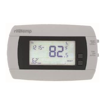
6030 Features This thermostat can be used with all millivolt and 24VAC heating and cooling systems. It cannot be used with line voltage systems. This thermostat is digital and your desired heat or cool temperatures can be easily be set on the large touch screen with the UP/DOWN arrows. -
Page 14: Jumper Reference
3 Wire Zoned Hot Water Solenoid Valves W or W1 W2 Y (the 3rd wire) W Jumper Reference Configuration jumpers allow your 6030 to be adapted to many different HVAC control applications. RESET UNIT AFTER CHANGING JUMPERS HVAC HP-AUX HEAT TYPE... - Page 15 H E AT O FF C O O L FA N A U TO ME NU PR OG Customer Support: 877-505-2353 or Visit our website www.ritetemp-thermostats.com 1611-024...
Need help?
Do you have a question about the 6030 and is the answer not in the manual?
Questions and answers