Table of Contents
Advertisement
Quick Links
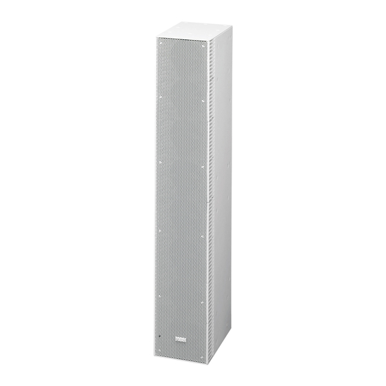
AcTIve LINe ArrAy SpeAker SySTeMS
WALL MOUNTINg ADApTer
WALL MOUNTINg ADApTer
exTeNSION pLATe
WALL MOUNTINg brAckeT
HOISTINg brAckeT
FIxINg bAr
Thank you for purchasing TOA's Active Line Array Speaker System.
Please carefully follow the instructions in this manual to ensure long, trouble-free use of your equipment.
Optional products
INSTALLATION MANUAL
Sr-D8-M, Sr-D8-S
Sr-D8cS
Sr-D8cL
Sr-D8ep
Sr-D8Wb
Sr-D8Hb
Sr-D8Fb
Advertisement
Table of Contents

Related Manuals for Toa SR-D8- M


Summary of Contents for Toa SR-D8- M
- Page 1 Sr-D8cL exTeNSION pLATe Sr-D8ep WALL MOUNTINg brAckeT Sr-D8Wb HOISTINg brAckeT Sr-D8Hb FIxINg bAr Sr-D8Fb Thank you for purchasing TOA’s Active Line Array Speaker System. Please carefully follow the instructions in this manual to ensure long, trouble-free use of your equipment.
-
Page 2: Table Of Contents
TAbLe OF cONTeNTS 1. IMpOrTANT SAFeTy INSTrUcTIONS ........... 3 2. SAFeTy precAUTIONS ................4 3. geNerAL DeScrIpTION ................6 4. FeATUreS ......................6 5. INSTALLATION precAUTIONS ............. 7 6. HANDLINg precAUTIONS ..............7 7. NOMeNcLATUre AND FUNcTIONS ..........8 8. brAckeTS ...................... -
Page 3: Important Safety Instructions
1. IMpOrTANT SAFeTy INSTrUcTIONS • Read these instructions. • Keep these instructions. • Heed all warnings. • Follow all instructions. • Do not use this apparatus near water. • Clean only with dry cloth. • Do not block any ventilation openings. Install in accordance with the manufacturer's instructions. • Do not install near any heat sources such as radiators, heat registers, stoves, or other apparatus (including amplifiers) that produce heat. -
Page 4: Safety Precautions
2. SAFeTy precAUTIONS • Before installation or use, be sure to carefully read all the instructions in this section for correct and safe operation. • Be sure to follow all the precautionary instructions in this section, which contain important warnings and/or cautions regarding safety. • After reading, keep this manual handy for future reference. Safety Symbol and Message conventions Safety symbols and messages described below are used in this manual to prevent bodily injury and property damage which could result from mishandling. Before operating your product, read this manual first and understand the safety symbols and messages so you are thoroughly aware of the potential safety hazards. - Page 5 • Should the following irregularity be found during power supply cord when making cable connections. use, immediately unplug the power supply cord and contact your nearest TOA dealer. Make no further When the Unit is in Use attempt to operate the unit in this condition as this • Do not place heavy objects on the unit as this may...
-
Page 6: General Description
3. geNerAL DeScrIpTION The TOA SR-D8-M and SR-D8-S are all-in-one Active Line Array Speaker Systems, each featuring a CobraNet digital audio input (SR-D8-M only), digital signal processor, digital power amplifier, and speakers configured in a line array. Precise control of the speaker’s vertical directivity and acoustic beamwidth makes it possible to create fully optimized sound spaces in a wide range of locations. -
Page 7: Installation Precautions
5. INSTALLATION precAUTIONS To avoid equipment failures, do not install the speaker in locations exposed to high temperatures or high humidity, such as indoor swimming pools. 6. HANDLINg precAUTIONS • The supplied power supply cord is designed for exclusive use with this unit. Never use it with other equipment. • Install the unit in locations where the temperature is between 0 and +40 °C (32 and 104°F) and the moisture is less than 90% (no dew condensation must be formed). • The units are precision audio components. To prevent failure, avoid locations where the unit may be exposed to strong shocks or vibrations. -
Page 8: Nomenclature And Functions
7. NOMeNcLATUre AND FUNcTIONS • SR-D8-M [Rear Terminals] [Front] [Rear] [Bottom Terminals] • SR-D8-S [Rear Terminals] [Front] [Rear] [Bottom Terminals]... - Page 9 1. Status indicator (green) [LeD] Lights when the speaker is placed in fault state* No functions assigned ACTIVE indicator This indicator may light arbitrarily during PC (always unlit) communication using the SR-D8 PC Software. The state in which audio signal can be directly input from the Analog 1 input terminal (4) to a digital amplifier without passing through the speaker’s internal CPU by shorting the fault...
- Page 10 10. LAN connection terminal [LAN] 13. Local link through terminal [LOcAL LINk THrOUgH] For PC communication using the SR-D8 PC Software. Outputs signals from SR-D8-M to SR-D8-S’s Connects to a 100BASE-TX-compatible network. Local link input terminal (14) when interconnecting Connect this terminal to a PC via a switching hub. SR-D8-M and SR-D8-S units in 3-unit or 4-unit Use RJ45 connector.
-
Page 11: Brackets
8. brAckeTS • SR-D8CS Wall Mounting Adapter • SR-D8EP Extension Plate L bracket R bracket Hex bolt M8×25 (with spring and plain washers) ... 4 • SR-D8CL Wall Mounting Adapter Hex bolt M6×20 (with spring and plain washers, paint) ... 16 •... -
Page 12: Communications Between Pc And Speakers
9. cOMMUNIcATIONS beTWeeN pc AND SpeAkerS Connect the PC to the SR-D8-M’s/SR-D8-S’s LAN connection terminal via a switching hub. Use a straight through cable (STP Category 5 or higher cable fitted with RJ45 connectors) for connection. Up to 4 stacks (up to 16 speakers) can be controlled by a single PC. Note: Do not connect the LAN terminal directly to the PC. PC with the SR-D8 PC Software installed Switching hub... -
Page 13: Connections
10. cONNecTIONS 10.1. connection example 1 (cobraNet connection) BGM player (Cassette deck, CD player, MD player, etc.) Microphone Digital mixer D-2008SP D-2000DA1 D-936R D-2000AD1 Switch SR-D8-M CobraNet Rear terminals Switching hub CobraNet Bottom terminals... -
Page 14: Connection Example 2 (Cobranet Connection, 4-Unit Configuration)
10.2. connection example 2 (cobraNet connection, 4-Unit configuration) BGM player (Cassette deck, Microphone CD player, MD player, etc.) Digital mixer D-2008SP D-2000DA1 D-936R D-2000AD1 Switch SR-D8-M CobraNet Rear terminals CobraNet Switching hub Switching hub (for CobraNet) Bottom (for LAN) terminals SR-D8-S Rear terminals... -
Page 15: Connection Example 3 (Analog Line Connection)
10.3. connection example 3 (Analog Line connection) BGM player (Cassette deck, CD player, MD player, etc.) Microphone Digital mixer D-2008SP D-2000DA1 D-936R D-2000AD1 Analog line Switch SR-D8-M Rear terminals Switching hub Bottom terminals... -
Page 16: Connection Example 4 (Maximum System)
10.4. connection example 4 (Maximum System) BGM player (Cassette deck, Microphone CD player, MD player, etc.) Digital mixer D-2008SP D-2000DA1 To B-1 To C-1 To D-1 D-936R D-2000AD1 Stack A Switch SR-D8-M Rear terminals Switching hub Switching hub (1) (for CobraNet) (for LAN) Bottom terminals... - Page 17 To D-3 To switching hub (1) Switching hub (2) (for LAN) To B-3 To C-3 Stack B Stack C Stack D SR-D8-M SR-D8-M SR-D8-M SR-D8-S SR-D8-S SR-D8-S SR-D8-S SR-D8-S SR-D8-S SR-D8-S SR-D8-S SR-D8-S...
-
Page 18: Removable Terminal Plug Connection
10.5. removable Terminal plug connection Notes • Avoid soldering stranded or shielded cable, as contact resistance may increase when the cable is tightened and the solder is crushed, possibly resulting in an excessive rise in joint temperatures. • When connecting 2 cables or a shielded cable to a single terminal, use a ferrule terminal with an insulation sleeve to crimp the cables because such cable conductors could become loose. Use the No. 4 ferrule terminal when connecting 2 cables to a single terminal. -
Page 19: Fixing Power Supply Cord
10.6. Fixing power Supply cord To prevent the power supply cord from being SR-D8-M rear SR-D8-S rear accidentally pulled out, fix it using the supplied cord clamp as shown at right. Cord clamp Cord clamp Power cord (supplied Power cord (supplied with the SR-D8-M) with the SR-D8-S) -
Page 20: System Expansion Using Cobranet Connection
10.7. System expansion Using cobraNet connection 10.7.1. cobraNet connection outline The system can be expanded by connecting the SR-D8-M’s CobraNet terminals to the D-2008SP with the D-2000CB CobraNet Interface Module. Connect the SR-D8-M to the D-2008SP via a switching hub. Connect each of CobraNet Primary and Secondary ports of the SR-D8-M to the same switching hub or different switching hubs connected in cascade. - Page 21 [connection example 1: redundant configuration of switching hubs] SR-D8-M CobraNet PRIMARY CobraNet SECONDARY SW-HUB SW-HUB SW-HUB SW-HUB CobraNet CobraNet PRIMARY CobraNet unit A SECONDARY (Operating) SW-HUB CobraNet unit B SW-HUB CobraNet CobraNet PRIMARY SECONDARY (Operating) As shown in the example above, when the CobraNet unit A is operating via the CobraNet PRIMARY and the CobraNet unit B is operating via the CobraNet SECONDARY, 6 switching hubs are used for communications between both units. Therefore, in a redundant configuration of switching hubs*, the number of hubs cascade- connected from the SR-D8-M should be 3 or less.
- Page 22 • Audio signals may be interrupted temporarily at the time when the network configuration automatically changes due to failure of any switching hub or disconnection of the main line. • Contact your TOA dealer for more information on switching hubs. Category 5 or higher standard straight through cable for LAN (with RJ45 connectors)
- Page 23 Shown below is the connection example of the 4 stack configuration, in which each SR-D8-M is connected to the same switching hub. In the connection example below, both CobraNet PRIMARY and SECONDARY terminals of each unit are connected to the same switching hub. Notes • Cycle the entire system’s power after connection completion. • Contact your TOA dealer for more information on switching hubs. SR-D8-M SR-D8-M bottom terminals bottom terminals Switching hub Category 5 or higher standard straight through...
-
Page 24: Installation
11. INSTALLATION 11.1. Installing a Single Sr-D8-M Unit WArNINg • Attach the safety wire, strong enough to withstand heavy load, to the unit. • The apparatus shall be connected to a mains socket outlet with a protective earthing connection. • The socket-outlet shall be installed near the equipment and the plug (disconnecting device) shall be easily accessible. • Do not use this speaker in a flying installation. • Only install speaker units in locations that can structurally support the weight of the speaker and its mounting brackets (Total weight: 31 kg or 68.34 lb). - Page 25 Step 4. Remove screws from speaker sides. Step 8. Install bolts in left- and right-side mounting holes located in the upper part of the speaker Step 5. Securely tighten 6 angle adjustment bolts (4 bracket. on the upper side and 2 on the lower side) Step 9.
-
Page 26: Installing Sr-D8-M And Sr-D8-S(S) In Multi-Unit Configuration
11.2. Installing Sr-D8-M and Sr-D8-S(s) in multi-unit configuration Up to 3 SR-D8-S speaker units can be connected in series to one SR-D8-M. WArNINg • Attach the safety wire, strong enough to withstand heavy load, to the unit. • The apparatus shall be connected to a mains socket outlet with a protective earthing connection. • The socket-outlet shall be installed near the equipment and the plug (disconnecting device) shall be easily accessible. - Page 27 11.2.2. Wall mounting Below is the procedure for installation in 2-unit configuration. Step 1. Install anchor stud bolts in the wall (see the figure in the lower right). Note: For mounting dimensions in 3-unit and 4-unit configurations, see p. 30. Step 2. Assemble the bracket sets to be mounted to the wall. Step 3. Mount the assembled bracket sets to the wall. [Anchor Stud Bolt Mounting Dimensions (2-Unit Configuration)] Unit: mm (in) Bracket Mounting Anchor Stud Bolts (M10) To determine stud bolt projection from the wall surface, refer to the dimensions indicated below:...
- Page 28 Step 4. Remove screws from speaker sides. Step 5. Attach each speaker bracket to the speaker. Bracket Mounting position Remark Hoisting Bracket On top of the speaker stack Mount an eyebolt. Use only for hoisting the speaker stack at speaker installation.
- Page 29 Step 7. Hang the loosely tightened bolts on the wall [Enlarged figure of previous page Part A] bracket. Step 8. Install bolts in left- and right-side mounting Hang on wall bracket. holes located in the upper part of the speaker bracket. Step 9.
- Page 30 Wall mounting methods for 3-unit and 4-unit configurations are the same as the mounting method for 2-unit configuration. Mount the speakers referring to the diagrams as shown below. 3-Unit configuration 4-Unit configuration Unit: mm (in) [Completed Dimensional [Completed Dimensional Diagram with Hoisting Diagram with Hoisting [Anchor Stud Bolt [Anchor Stud Bolt Bracket Mounted] Bracket Mounted] Mounting Dimensions] Mounting Dimensions] 373 (14.69) 373 (14.69)
-
Page 31: Angle Adjustment
11.3. Angle Adjustment WArNINg Never adjust the speaker angle to the left or right when the speaker unit is installed facing up or down. 11.3.1. Adjusting the angle to the left or right within 45° Step 1. Remove or loosen the bolts on the speaker bracket’s upper and lower sides. Perform this work for all speaker brackets. - Page 32 11.3.2. Adjusting the angle to the left or right over 45° Step 1. Remove or loosen the bolts on the speaker Step 3. Loosely secure the SR-D8FB Fixing Bar to bracket’s upper and lower sides. Perform this the speaker bracket’s upper side. Perform work for all speaker brackets.
-
Page 33: Dimensional Diagrams
12. DIMeNSIONAL DIAgrAMS 12.1. Sr-D8-M, Sr-D8-S Active Line Array Speaker Systems Unit: mm (in) [Top] [Rear] [Rear] [Front] [Side] (SR-D8-M) (SR-D8-S) 160 (6.3) 255 (10.04) 12.2. brackets 12.2.1. Sr-D8cL Wall Mounting Adapter 12.2.2. Sr-D8cS Wall Mounting Adapter Unit: mm (in) Unit: mm (in) 50 (1.97) 33 (1.3) - Page 34 12.2.3. Sr-D8ep extension plate Unit: mm (in) [L bracket] [r bracket] 15.2 (0.6) 15.2 (0.6) 194.2 (7.65) 194.2 (7.65) 12.2.4. Sr-D8Wb Wall bracket Unit: mm (in) [Wall bracket] [Speaker bracket] 167.4 (6.59) 295 (11.61) 120.4 (4.74) (2.05) 12.2.5. Sr-D8Hb Hoisting bracket Unit: mm (in) [Hoisting bracket] 170 (6.69)
-
Page 35: Specifications
To be connected via the specified switching hub Max. extend distance: 100 m (109.36 yd) (connected via a switching hub) Communication LOCAL LINK: TOA original digital audio transmission, Between Main and RJ45 receptacle (etherCON: NEUTRICK) Sub Speakers Connection cable: Shielded twisted pair (STP) CAT 5 or higher LAN cable Operating Temperature 0 to +40 ºC (32 to 104 ºF) -
Page 36: Brackets
Cet appareil numérique de la classe A est conforme à la norme NMB-003 du Canada. Traceability Information for Europe Manufacturer: Authorized representative: TOA Corporation TOA Electronics Europe GmbH 7-2-1, Minatojima-Nakamachi, Chuo-ku, Kobe, Hyogo, Suederstrasse 282, 20537 Hamburg, Japan Germany URL: http://www.toa.jp/...
Need help?
Do you have a question about the SR-D8- M and is the answer not in the manual?
Questions and answers