Table of Contents
Advertisement
Quick Links
LINE ARRAY SPEAKERS
RIGGING FRAME
RIGGING SUPPORT BRACKET
TILT JOINT BRACKET
CLUSTER BRACKET
Thank you for purchasing TOA Line Array Speaker. Please carefully follow the instructions in this manual to ensure
long, trouble-free use of your equipment
OPERATING INSTRUCTIONS
Note that casters must be prepared separately.
SR-C8L
SR-C8S
SR-C15B
SR-RF8
SR-SB8
SR-TP8
SR-CL8
Advertisement
Table of Contents

Subscribe to Our Youtube Channel
Related Manuals for Toa SR-C8L


Summary of Contents for Toa SR-C8L
- Page 1 RIGGING SUPPORT BRACKET SR-SB8 TILT JOINT BRACKET SR-TP8 CLUSTER BRACKET SR-CL8 Note that casters must be prepared separately. Thank you for purchasing TOA Line Array Speaker. Please carefully follow the instructions in this manual to ensure long, trouble-free use of your equipment...
-
Page 2: Table Of Contents
......10 8. DIGITAL PROCESSOR SETTINGS 8.1. SR-C8L and SR-C8S Systems ..................11 8.2. Combined SR-C8L or SR-C8S and SR-C15B Systems ..........12 9. FLYING SYSTEMS USING THE SR-RF8 RIGGING FRAME 9.1. Flying System Outline ....................13 9.2. Assembling the SR-RF8 Rigging Frame ................ 15 9.3. -
Page 3: Safety Precautions
1. SAFETY PRECAUTIONS • Be sure to read this safety instructions in this section carefully in prior to use. • Be sure to follow all the precautionary instructions in this section, which contain important warnings and/or cautions regarding safety. • After reading, keep this manual handy for future reference. Safety Symbol and Message Conventions Safety symbols and messages described below are used in this manual to prevent bodily injury and property damage which could result from mishandling. - Page 4 • Do not stand or sit on, nor hang down from the unit CAUTION as this may cause it to fall down or drop, resulting in personal injury and/or property damage. When the Unit is in Use • To avoid risks, warn others to stay away from the speaker or not to lean against it.
-
Page 5: General Description
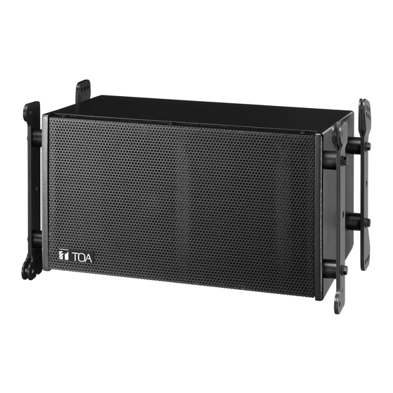
• The SR-C8L is a two-way speaker mounting a high-power 20 cm woofer and two compression drivers, and featuring a 5 degree angle of vertical directivity and 110 degrees of horizontal. It is ideal for long distance applications and can be powered by either one or two amplifiers. -
Page 6: Dimensional Diagrams
5. DIMENSIONAL DIAGRAMS 5.1. Speaker Systems 5.1.1. SR-C8L Line array speaker Unit: mm (Rear view) 526.6 [20.73"] 296 [11.65"] 470 [18.5"] (Left side view) (Front view) (Right side view) 5.1.2. SR-C8S Line array speaker Unit: mm (Rear view) 526.6 [20.73"] 470 [18.5"]... -
Page 7: Sub-Woofer Speaker System
5.2. Sub-Woofer Speaker System 5.2.1. SR-C15B Line array speaker Unit: mm (Rear view) 526.6 [20.73"] 470 [18.5"] 550 [21.65"] (Left side view) (Front view) (Right side view) 5.3. Frame and Brackets 5.3.1. SR-RF8 Rigging frame Unit: mm 167 [6.58"] 95 [3.74"] 16-M10 (For caster mounting) 71 [2.8"]... -
Page 8: Sr-Sb8 Rigging Support Bracket
5.3.2 SR-SB8 Rigging support bracket Unit: mm 270 [10.63"] (Top view) 517.5 [20.37"] 2-ø10.5 [ø0.41"] 20 [0.79"] 150 [5.91"] (Front view) 5.3.3. SR-TP8 Tilt joint bracket Unit: mm 294 [11.57"] 5.3.4 SR-CL8 Cluster bracket 15-ø13 [ø0.51"] Unit: mm 15 [0.59"] 20 [0.79"] 310 [12.2"] 4-ø10.5 [ø0.41"]... -
Page 9: Bi-Amplifier And Single-Amplifier Operations
6.1. Bi-Amplifier Operation 6.1.1. System diagram Woofer HIGH HIGH Mixer/ Digital Tweeter preamplifier processor Power amplifier SR-C8L/C8S 6.1.2. Internal wiring diagram Woofer Neutrik NL4MP connector Screw terminal HIGH HIGH Tweeter Input terminal panel 6.2. Single-Amplifier Operation 6.2.1. System diagram Woofer... -
Page 10: Switching To Single-Amplifier Operation Mode
7. SWITCHING TO SINGLE-AMPLIFIER OPERATION MODE To switch the speaker's bi-amplifier operation mode to single-amplifier operation, remove the speaker's rear input panel and change the speaker's internal wiring. Switching Power Modes Step 1. Remove the four screws securing the input terminal panel and pull out the panel. Step 2. -
Page 11: Digital Processor Settings
8. DIGITAL PROCESSOR SETTINGS Set the digital processor's parameters as follows: 8.1. SR-C8L and SR-C8S Systems 8.1.1. Bi-amplifier operation Filter Gain Delay Channel Polarity (dB) (msec) TYPE Freq. (Hz) Gain (dB) Pre-stage Filter 1.4k –3.0 0.700 LPF (12 dB) 2.0k 0.707... -
Page 12: Combined Sr-C8L Or Sr-C8S And Sr-C15B Systems
8.2. Combined SR-C8L or SR-C8S and SR-C15B Systems 8.2.1. Bi-amplifier operation Filter Gain Delay Polarity Channel (dB) (msec) TYPE Freq. (Hz) Gain (dB) Pre-stage Filter 1.4k 0.700 HPF (12 dB) 2.053 LPF (6 dB) Normal SR-C15B (Positive) LPF (12 dB) 0.500... -
Page 13: Flying Systems Using The Sr-Rf8 Rigging Frame
SR-C8L speakers together. Shown below is a basic flying system. Rigging frame SR-C15B SR-C8L SR-C8S The line array speaker's vertical directivity angle is 5 degrees for the SR-C8L and 15 degrees for the SR-C8S. [SR-C8L] [SR-C8S] 5 degrees 15 degrees... - Page 14 This flying system consists of four SR-C8L units, two SR-C8S units and one SR-C15B unit. To enhance long- distance sound transmission capabilities, the four SR-C8Ls are linked together at overlap angles of four, two and one degree. As a result of this, the system's overall vertical directivity angle is 43 degrees.
-
Page 15: Assembling The Sr-Rf8 Rigging Frame
9.2. Assembling the SR-RF8 Rigging Frame Assemble the rigging frame referring to the figure below. Ensure that fixing plates are correctly secured using two bolts (including plain and spring washers) supplied with the rigging frame for each plate. Since each fixing plate has its own installation position and orientation, refer to the figure for correct assembly. Be sure that the forward mounting holes are always used in flying applications. -
Page 16: Connecting The Rigging Frame To The Speaker
Connect the rigging frame to the speaker referring to the figures below. Confirm the positioning of the horn (SR-C8L and SR-C8S only), then correctly mount the rigging frame to the speaker by tightening the supplied nuts and bolts from both left and right sides. -
Page 17: Connection Between Speakers
9.4. Connection Between Speakers Inter-connect speaker sections referring to the figures below. Ensure that both speakers are securely connected by tightening the supplied nuts and bolts from both left and right sides. Since connection holes for setting the overlap angle are provided at the back of the speaker, assemble using the connection holes matching the required overlap angle. -
Page 18: About The Flying Installations
9.5. About the Flying Installations Cautions • Suspension wires and shackles are not supplied with the speaker. Separately prepare and use those which are strong enough to suspend the speaker system. Further, ensure that the ceiling structure from which the speaker system is suspended is also robust and capable of supporting the system's total weight. -
Page 19: Installing The Flying System Using The Sr-Cl8 Cluster Bracket
10. INSTALLING THE FLYING SYSTEM USING THE SR-CL8 CLUSTER BRACKET 10.1. Flying System Outline This flying system uses the SR-CL8 Cluster Bracket. Using the cluster bracket, up to four speakers can be connected to each other when suspending in vertical or horizontal orientation. Note that the sub-woofer cannot be installed using the cluster bracket. - Page 20 10.2.2. Vertical flying installation Cautions • Wires and shackles to be used for suspension are not supplied with the speaker. Separately prepare and use those which are strong enough to suspend the speaker system. Further, ensure that the ceiling structure from which the speaker system is suspended is also robust and capable of standing the system's total weight.
-
Page 21: Horizontal Flying
• Add an anti-swing guy wire as required. However, take care that the speaker's weight is not applied to the wire. Anti-swing guy wire 10.3. Horizontal Flying 10.3.1. Cluster bracket attachment Attach the cluster brackets to the leftmost and rightmost of the connected speakers referring to the figure below. - Page 22 10.3.2. Horizontal Flying Installation Cautions • Wires and shackles to be used for suspension are not supplied with the speaker. Separately prepare and use those which are strong enough to suspend the speaker system. Further, ensure that the ceiling structure from which the speaker system is suspended is also robust and capable of standing the system's total weight.
-
Page 23: Speaker Stacking
It is possible to stack the line array speakers using the SR-RF8 Rigging Frame. Up to eight speakers can be stacked, noting that each line array speaker is calculated as 1 unit and each SR-C15B sub-woofer as 2 units. Shown below is a basic stack system. Note that casters must be prepared separately. SR-C8L SR-C15B Rigging support bracket... -
Page 24: Assembling The Sr-Rf8 Rigging Frame
11.2. Assembling the SR-RF8 Rigging Frame Before assembly, first determine whether to set the mounting position of the fixing plate at the center or forward, taking the stack system's center of gravity into consideration. Ensure that fixing plates are correctly secured using two bolts (including plain and spring washers) supplied with the rigging frame for each plate. -
Page 25: Connecting The Rigging Frame To The Speaker
11.3. Connecting the Rigging Frame to the Speaker Connect the rigging frame to the speaker referring to the following figure. Correctly connect both units by tightening the supplied nuts and bolts from both the left and right sides. When using the SR-C15B sub-woofer in the stack system, mount it in the lowermost position (i.e. immediately above the rigging frame). -
Page 26: About Stacking
11.5. About Stacking • Separately prepare casters and mounting hardware, which function as the rigging frame's feet. • When stacked, the overhang of the front or rear portion of the line array speaker cannot extend more than 10 cm beyond the edge of the rigging frame. Notes •... -
Page 27: Using The Sr-Sb8 Rigging Support Bracket
12. USING THE SR-SB8 RIGGING SUPPORT BRACKET The SR-SB8 Rigging Support Bracket is used to prevent the stacked SR-C8 series line array speakers from tipping over. Be sure the SR-SB8 is used whenever six or more SR-C8 series speakers are stacked. Count the SR-C15B sub-woofer as two units when configuring a system. -
Page 28: Frequent Attachment And Detachment Of The Rigging Support Bracket
12.3. Frequent Attachment and Detachment of the Rigging Support Bracket Quick release pins are convenient way of quickly attaching and detaching the rigging support bracket. Quick release pins Rigging support bracket Quick release pins Notes • Quick release pins are not supplied with the speaker. •... -
Page 29: Tilting The Speaker Downward
[Attachment to the sub-woofer] Tilt joint bracket SR-TP8 Tilt joint bracket SR-TP8 Representative stacking example using the tilt joint bracket [SR-C15B x 1, SR-C8S x 1, SR-C8L x 3] [SR-C8S x 1, SR-C8L x 4] 5degrees 15degrees 5degrees 15degrees Note Avoid using the tilt joint bracket for connections between the line array speakers (except the sub-woofer) or between the sub-woofer and the rigging frame, as well as in flying applications. -
Page 30: Specifications
14. SPECIFICATIONS 14.1. SR-C8L and SR-C8S Model No. SR-C8L SR-C8S Enclosure Bass-reflex type Allowable Input Continuous program: 360 W (single-amplifier operation) Low frequency: 360 W, high frequency: 180 W (bi-amplifier operation) Rated Impedance 16 Ω (single-amplifier operation) Low frequency: 16 Ω, high frequency: 16 Ω (bi-amplifier operation) -
Page 31: Sr-Rf8
14.3. SR-RF8 Applicable Speaker SR-C8L, SR-C8S and SR-C15B No. of Mountable Speakers Flying: Max. 12 speakers (optional SR-C15B is counted as 2 units) Stacking: Max. 8 speakers (optional SR-C15B is counted as 2 units) Finish Rolled steel plate, black, paint... - Page 32 Traceability Information for Europe (EMC directive 2004/108/EC) Manufacturer: Authorized representative: TOA Corporation TOA Electronics Europe GmbH 7-2-1, Minatojima Nakamachi, Chuo-ku, Kobe, Hyogo, Suederstrasse 282, 20537 Hamburg, Japan Germany URL: http://www.toa.jp/ 133-01-473-2A...
Need help?
Do you have a question about the SR-C8L and is the answer not in the manual?
Questions and answers