Linear DVS 1200 Installation Instructions Manual
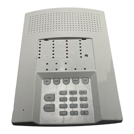
Supervised wireless security console
Hide thumbs
Also See for DVS 1200:
- Software manual (48 pages) ,
- Installation & programming instructions (44 pages) ,
- Installation instructions manual (44 pages)

Related Manuals for Linear DVS 1200


Summary of Contents for Linear DVS 1200
- Page 1 SUPERVISED WIRELESS SECURITY CONSOLE Installation & Programming Instructions (760) 438-7000 FAX (760) 438-7043 USA & Canada (800) 421-1587 & (800) 392-0123 Toll Free FAX (800) 468-1340...
- Page 2 INTRODUCTION CONGRATULATIONS for selecting Linear’s DVS-1200 Security System. The DVS-1200 Console incorporates many advanced and sophisticated features. The system can be expanded and customized to fit the installation’s specific needs. The DVS-1200 Console and its accessories are designed and manufactured by the oldest wireless security company in North America.
-
Page 3: Table Of Contents
IMPORTANT INFORMATION ....... . 42 LINEAR LIMITED WARRANTY ......42 WIRELESS PRODUCT NOTICE . -
Page 4: The Dvs-1200 Security System
The Console can be programmed locally using its own With a monitored system, the central station can dispatch keypad, or remotely, using Linear’s Model RA-2400 authorities in case of burglary, fire or other emergency. The Remote Access software program. The RA-2400... -
Page 5: Door/Window Sensors
DOOR/WINDOW SENSORS PANIC BUTTONS The DXS-31 sensors monitor doors and windows. They send The DXT-21 and DXT-23 transmitters can be used as portable radio signals to the Console. One type of signal is sent when “panic buttons”. Pressing the front or top button on the DXT-21 the door or window is opened, and a different type of signal is at any time will trigger the emergency siren. -
Page 6: Security System Floor Plan
2. SECURITY SYSTEM FLOOR PLAN EXAMPLE SYSTEM The example shows a typical DVS-1200 system. Any or all of the accessories shown can be used. A total of 12 sensors (including keypads) can be used with each Console. DESIGN THE INSTALLATION Create a floor plan of the installation. -
Page 7: Typical System Sensors
3. TYPICAL SYSTEM SENSORS DOOR/WINDOW SENSOR Sensor mounts on door or window with adjacent magnet. Opening door or window moves magnet away, triggering sensor. Pressing the case causes sensor to send a test signal. Jumper inside for INSTANT or DELAYED alarm setting. -
Page 8: Console Features
4. CONSOLE FEATURES MODE INDICATORS Specific indicator will light showing the mode the Console is in. HOME indicator will blink during secure exit and home instant modes. AWAY indicator will blink during the exit delay in the Away Mode. CONSOLE STATUS INDICATORS Show the current status of the Console. - Page 9 AUXILIARY FUSE RADIO TEST POINTS Type 2AG, 1-amp fuse. Used to monitor the Console’s radio receiver during troubleshooting. Protects the external relay output when used with wet contacts (12 VDC Provides connection for an audio amplifier to listen to the receiver’s output. switched out).
-
Page 10: Console Installation
5. CONSOLE INSTALLATION CONSOLE LOCATION NOTE: Sensor signals must be able to reach the Console. Try to centrally locate the Console. Keep Console away from large metal USE A PAPER appliances. CLIP TO REMOVE Maximum recommended sensor range is THE CLEAR DISPLAY WINDOW 400 feet (system tested at 1000 feet). -
Page 11: External Console Speaker Connection (Optional)
With the VB-2 module installed, the Central Station can talk to the occupants through the external console speaker. Use an 8-ohm, 10 watt minimum rated LINEAR SECURITY CONSOLE MODEL DVS-1200 speaker. Do not use a horn/siren with a MAIN TERMINAL BLOCK built-in siren driver. -
Page 12: Telephone Line Connection (Optional)
TELEPHONE LINE CONNECTION (OPTIONAL) TELEPHONE Connect the Console to the telephone line if TERMINAL LINEAR SECURITY CONSOLE MODEL DVS-1200 BLOCK the system is monitored, requires 2-way audio, or requires telephone remote command. TELEPHONE TERMINAL BLOCK SEIZED RING Telephone ring & tip terminals are for... -
Page 13: Console Power Connection
CONSOLE POWER CONNECTION The Console is powered by a low voltage LINEAR SECURITY CONSOLE MODEL DVS-1200 MAIN TERMINAL BLOCK plug-in transformer. Use up to 25 feet of 20 AWG or larger EXT. SPKR two-conductor wire to connect the transformer PLUG-IN TRANSFORMER... -
Page 14: Basic Console Programming
6. BASIC CONSOLE PROGRAMMING In a new installation, when power is first applied, the Console’s master user code is “1234”. CHANGE THE MASTER USER CODE NOTE: Local programming must be entered on the Console’s keypad, not on a wireless remote keypad. ENTERING SETTING A SETUP... -
Page 15: Programming Different Sensor Types
PROGRAMMING DIFFERENT SENSOR TYPES Follow the instructions on the previous page to select a sensor number to program the sensor into. NOTE: A sensor can be programmed into more than one location. Be sure to choose an unused sensor number. If a sensor gets entered into more than one location, delete the duplicates using the remove sensor function. -
Page 16: Basic Sensor Installation
7. BASIC SENSOR INSTALLATION Each accessory sensor is packaged with its own set of installation instructions specific to the model of sensor. FROM TOP OF CASE TWIST SCREWDRIVER BETWEEN Refer to the sensor’s instructions for details on CASE HALVES UNTIL IT installing, operating, and testing of the sensor. -
Page 17: Dxs-31 Door/Window Sensors
EXAMPLE INSTALLATIONS DXS-31 DOOR/WINDOW SENSORS LEFT OPENING DOOR The DXS-31 sensors can be used to monitor SLIDING WINDOW TRANSMITTER doors, windows, cabinets, crawl space doors, MOUNTED ON DOOR JAMB MAGNET MOUNTED gates, freezer doors, and many other moving ON WINDOW FRAME objects that could be used for intrusion or (NOTE: SMALL END OF TRANSMITTER UP) -
Page 18: Customizing The Console
8. CUSTOMIZING THE CONSOLE The Console can be customized for the specific installation. USE SENSOR LABELS PROVIDED A label sheet with sensor location names is provided with the Console. Labeling the sensors allows quick and easy identification of where any alarms have occurred, where a sensor with a low battery is, WRITE IN SPECIAL where a sensor with radio trouble is, etc. -
Page 19: Console Operating Modes
9. CONSOLE OPERATING MODES OFF MODE Use this mode to disarm the burglary portion of the system. OFF MODE Switching to Off Mode stops any alarms in progress. START HERE The 24-hour functions are still active in Off Mode and can be triggered by pressing the (OPTIONAL) [ FIRE ] or [ EMERGENCY ] button. -
Page 20: Home Mode
HOME MODE MANUAL BYPASSING OF SENSORS Use this mode when sleeping or when anyone Manual bypassing of sensors in the Home is staying inside. Mode allows arming of the system at night with open windows, while still having Home Mode causes an instant alarm when perimeter protection with other closed doors any perimeter sensor is triggered. -
Page 21: Away Mode
AWAY MODE MANUAL BYPASSING OF SENSORS Use this mode when no one will be staying home. Manual bypassing of sensors in the Away Mode allows arming of the system with open Each burglary sensor can trigger the siren once doors and windows, while still having per arming period. -
Page 22: Test Mode
TEST MODE Even though this is a self-monitoring supervised system, the National Burglar and Fire Alarm Association recommends that all security systems should be tested manually on a regular basis. The Console must be in Off Mode before going TEST MODE to Test Mode. -
Page 23: System Trouble Indications
10. SYSTEM TROUBLE INDICATIONS The DVS-1200 Console is a self-monitoring supervised wireless system. If the Console detects a problem with any of the supervised system sensors or backup battery, it will display the appropriate trouble indication and, if monitored, report the trouble to the Central Station through the communicator (depending on communicator programming). -
Page 24: Customizing The System
11. CUSTOMIZING THE SYSTEM Adding additional sensors will increase the protection provided by the system. All ground-level perimeter openings and accessible upper-story openings need protection. Motion detectors can protect interior areas and areas where valuables are kept. START IN TEST ADDING SENSORS TO THE SYSTEM Always start with the Console in Test Mode (enter a user code and press [ TEST ]). -
Page 25: Making A Sensor A 24-Hour Door Chime
MAKING A SENSOR A 24-HOUR DOOR CHIME START IN TEST Sensors can be programmed to cause the Console to chime any time they’re activated. Chime-only sensors will not be able to trigger MASTER the alarm in any Console mode. USER The sensor must have already been learned CODE by the Console (see “Adding sensors to the... -
Page 26: Making A Sensor Activate A Different Zone
MAKING A SENSOR ACTIVATE A DIFFERENT ZONE Any sensor can be reprogrammed to activate START IN TEST any of the Console’s zones. The sensor must have already been learned by the Console (see “Adding sensors to the MASTER System” for details). USER Start with the Console in Test Mode. -
Page 27: Advanced Programming
12. ADVANCED PROGRAMMING To perform any of the advanced programming SETUP MODE steps, the Console must be in the Setup Mode. Start with the Console in Test Mode (Setup Each programming function is performed with Mode cannot be reached from any other similar keystrokes. -
Page 28: Changing A Sensors Supervision
CHANGING A SENSORS SUPERVISION When a sensor is programmed, the Console SENSOR NUMBER TO CHANGE automatically recognizes it as supervised or non-supervised. PROGRAM HOME The Console expects hourly status transmissions from any sensor programmed as supervised. 16 FOR NON-SUPERVISED 17 FOR SUPERVISED Any sensor can be programmed as supervised or non-supervised. -
Page 29: Fire Siren Time
FIRE SIREN TIME The factory-set fire siren time is five minutes PROGRAMMING STEP #32 (UL installation maximum). The fire siren time can be adjusted from one PROGRAM HOME to 30 minutes. TIME IN MINUTES (1-30) AWAY STORE PROGRAM AUTOMATION OUTPUT TIME The factory setting causes the Automation PROGRAMMING STEP #40 Output to toggle between on and off with each... -
Page 30: Silent Burglary Alarms
SILENT BURGLARY ALARMS The factory setting causes audible burglary alarms. PROGRAMMING STEP #63 Alternately, the Console can be programmed for silent burglary alarms. PROGRAM HOME 0 FOR AUDIBLE BURG 1 FOR SILENT BURG STORE PROGRAM AWAY SILENT EMERGENCY ALARMS The factory setting causes audible emergency alarms. -
Page 31: Automation Output Mode During Alarm
AUTOMATION OUTPUT MODE DURING ALARM NOTE: For the Automation Output to activate during an alarm, that function must be enabled PROGRAMMING STEP #68 with Programming Step 71 or 72. If the Automation output is programmed to PROGRAM HOME activate during an alarm, it can be 0 FOR FLASHING OUTPUT ON ALARM programmed to flash or be steady. -
Page 32: Automation Output While Armed
AUTOMATION OUTPUT WHILE ARMED The factory setting causes the Console’s PROGRAMMING STEP #73 Automation Output to activate when pressing the [ (A) ] key, or when it’s triggered with a PROGRAM HOME two-button remote control. 0 FOR STANDARD TRIGGER In addition, the Console can be programmed 1 FOR OUTPUT WHEN ARMED to activate the Automation Output when the AWAY... -
Page 33: Additional User Codes
ADDITIONAL USER CODES PROGRAMMING STEPS The Console can be programmed with five #93 TO 98 restricted user codes and one page alert user code. The additional codes operate the system as PROGRAM usual, but cannot access Setup Mode. The additional codes can access a special 1-5 DIGIT CODE Code Mode that can be used to change or (3-5 DIGITS RECOMMENDED) -
Page 34: Communicator Programming
13. COMMUNICATOR PROGRAMMING SETUP MODE To perform any of the communicator programming steps, the Console must be in the Setup Mode. Each programming function is performed with similar keystrokes. After the Console is in SETUP MODE Setup Mode, enter the programming step number, press the [ HOME ] key (HOME = START IN TEST program), enter the new value, and press the... -
Page 35: General Communicator Options
REMOTE LOCKOUT The factory setting for the communicator is to PROGRAMMING STEP #100 allow remote connection to the Console with Linear’s RA-2400 Remote Access Software PROGRAM HOME and a modem (unlocked). 0 FOR UNLOCK Alternately, the Console can be programmed... -
Page 36: Call Limiter
CALL LIMITER The factory setting for the call limiter is OFF. PROGRAMMING STEP #101 This allows the communicator to report burglary alarms, once for each sensor, as many times as they are triggered. PROGRAM HOME Optionally, the Console can be programmed 0 FOR OFF (UNLIMITED) to only allow five burglary reports total per 1 FOR ON (5 VIOLATIONS) -
Page 37: Communicator Reporting Options
COMMUNICATOR REPORTING OPTIONS REPORTING FORMAT The factory setting causes the communicator to report using the 4 by 2 format. This format PROGRAMMING STEP #105 allows four-digit account numbers from 0000 to 9999 and provides two-digit alarm codes. PROGRAM HOME Alternately ADEMCO CONTACT ID can be chosen as a reporting format. -
Page 38: Account Number
ACCOUNT NUMBER The communicator’s account number entered PROGRAMMING STEP #88 must be 4-digits long. The factory setting for the account number is PROGRAM HOME 0000. Enter an account number from 0000 to 9999. 4 DIGIT ACCOUNT NUMBER AWAY STORE PROGRAM PRIMARY TELEPHONE NUMBER The primary Central Station telephone number can be up to 20-digits long. -
Page 39: Report Console Trouble
REPORT CONSOLE TROUBLE The factory setting does not report Console trouble events to the Central Station. PROGRAMMING STEP #108 Alternately, the communicator can be programmed to report Console trouble events. PROGRAM These include all conditions that light the Console’s BATTERIES or TROUBLE indicator. 0 FOR NO CONSOLE TROUBLE It also includes low Console backup battery. -
Page 40: Communicator Reporting Codes
COMMUNICATOR REPORTING CODES The two-digit communicator reporting code for each event has a factory set value. These values may be customized to fit the specific installation and the reporting requirements of the Central Station monitoring the system. If Point ID reporting is enabled (the factory = REMOVE = PROGRAM default setting), each sensor can report a... -
Page 41: Force Arming Reporting Code
FORCE ARMING REPORTING CODE Programming Step #258 The factory set reporting code for force PROGRAMMING STEP #258 arming is “65” (Code 574 with Ademco). Any value from 0-99 can be programmed for PROGRAM HOME this event (0 = no report). NOTE: For force arming reporting, force arming 0 - 99 FOR FORCE ARMING REPORTING CODE... -
Page 42: By 2 Format Point Id Reporting Codes
4 BY 2 FORMAT POINT ID REPORTING CODES 4 BY 2 FORMAT POINT ID ALARM REPORT CODES Refer to the 4 by 2 Format Point ID Reporting Code table to view/edit the alarm reporting codes for each of the 12 sensors. The DVS12K24.EPS communicator will send these codes if Point ID is enabled and any sensor triggers an... - Page 43 POINT ID REPORTING CODES PROGRAMMING POSSIBLE FACTORY INSTALLATION STEP # FUNCTION VALUES VALUE VALUE SENSOR 1 ALARM REPORT CODE 0 - 99 SENSOR 2 ALARM REPORT CODE 0 - 99 SENSOR 3 ALARM REPORT CODE 0 - 99 SENSOR 4 ALARM REPORT CODE 0 - 99 SENSOR 5 ALARM REPORT CODE 0 - 99...
-
Page 44: Important Information
There family: are no obligations or liabilities on the part of Linear Corporation for consequential damages arising out of or in connection with use or Status of bedroom doors.
Need help?
Do you have a question about the DVS 1200 and is the answer not in the manual?
Questions and answers