Sign In
Upload
Download
Table of Contents
Contents
Add to my manuals
Delete from my manuals
Share
URL of this page:
HTML Link:
Bookmark this page
Add
Manual will be automatically added to "My Manuals"
Print this page
×
Bookmark added
×
Added to my manuals
Manuals
Brands
Kramer Manuals
Media Converter
VM-1010
User manual
Kramer VM-1010 User Manual
Video distributor
Hide thumbs
Also See for VM-1010
:
User manual
(23 pages)
,
User manual
(25 pages)
1
Table Of Contents
2
3
4
5
6
7
8
9
10
11
12
13
14
15
16
17
18
19
20
21
22
23
24
25
26
27
page
of
27
Go
/
27
Contents
Table of Contents
Bookmarks
Table of Contents
User Manual
Table of Contents
1 Introduction
2 Getting Started
Achieving the Best Performance
3 Installing in a Rack
4 Your VM-1010
Overview
Figure 1: VM-1010 Programmable Video Distributor Front Panel
Figure 2: VM-1010 Programmable Video Distributor Rear Panel
Connecting the VM-1010
Figure 3: Connecting the VM-1010
VM-1010 Technical Specifications
5 Your VM-1021
Overview
Figure 4: VM-1021 1:20 Video Distributor Front Panel
Figure 5: VM-1021 1:20 Video Distributor Rear Panel
Connecting the VM-1021
Figure 6: Connecting the VM-1021
VM-1021 Technical Specifications
6 Your VM-1055
Overview
Figure 7: VM-1055 Video Component Distributor Front Panel
Figure 8: VM-1055 Video Component Distributor Rear Panel
Connecting the VM-1055
Figure 9: Connecting the VM-1055
VM-1055 Technical Specifications
7 Your
Overview
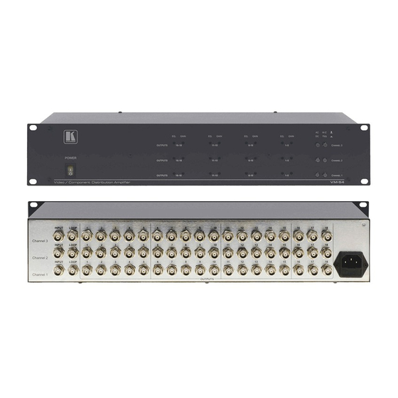
Figure 10: VM-54 Video/Component Distributor Amplifier Front Panel
Figure 11: VM-54 Video/Component Distributor Amplifier Rear Panel
Connecting the
Figure 12: Connecting the
VM-54 Technical Specifications
Advertisement
Quick Links
Download this manual
KR AMER ELECTRON ICS LT D.
USER MANUAL
MODELS:
VM-1010
Programmable Video
Distributor
VM-1021
1:20 Video Distributor
VM-1055
Video Component Distributor
VM-54
Video/Component Distributor
Amplifier
P/N: 2900-300182 Rev 1
Table of
Contents
Previous
Page
Next
Page
1
2
3
4
5
Advertisement
Table of Contents
Need help?
Do you have a question about the VM-1010 and is the answer not in the manual?
Ask a question
Questions and answers
Related Manuals for Kramer VM-1010
Amplifier Kramer VN-1055 User Manual
Distribution amplifiers (25 pages)
Amplifier Kramer VM-1010 User Manual
Kramer vm-1010 distribution amplifiers: user guide (23 pages)
Media Converter Kramer VM-100C User Manual
1:10 video component distributor (11 pages)
Media Converter Kramer VM-100CB User Manual
1:10 video component distributor (12 pages)
Media Converter Kramer VM-100CA User Manual
1:10 video component / audio distributor (14 pages)
Media Converter Kramer VM-1120 User Manual
1:10 balanced stereo audio distributor (10 pages)
Media Converter Kramer VM-1120 User Manual
1:10 balanced stereo audio distributor (16 pages)
Media Converter Kramer VM-1610 User Manual
(14 pages)
Media Converter Kramer VM-1610 Quick Start Manual
(2 pages)
Media Converter Kramer VM-127 User Manual
3/6/12 channel video clamper (14 pages)
Media Converter Kramer VM-16HDMI User Manual
1:8/1:16 hdmi distributor (15 pages)
Media Converter Kramer VM-8H User Manual
1:8 hdmi distributor and 1:16 hdmi distributor (16 pages)
Media Converter Kramer VM-8H User Manual
1:8 hdmi distributor; 1:16 hdmi distributor (17 pages)
Media Converter Kramer VM-1110xl User Manual
Balanced audio distributor (9 pages)
Media Converter Kramer VM-1110xl User Manual
Balanced audio distributor (14 pages)
Media Converter Kramer VM-1110xl Quick Start Manual
(2 pages)
This manual is also suitable for:
Vm-54
Vm-1021
Vm-1055
Table of Contents
Print
Rename the bookmark
Delete bookmark?
Delete from my manuals?
Login
Sign In
OR
Sign in with Facebook
Sign in with Google
Upload manual
Upload from disk
Upload from URL


Need help?
Do you have a question about the VM-1010 and is the answer not in the manual?
Questions and answers