
Subscribe to Our Youtube Channel
Related Manuals for Elmo MO-1


Summary of Contents for Elmo MO-1
- Page 1 INSTRUCTION MANUAL VISUAL PRESENTER MO-1 Please read this instruction manual carefully before using this product and keep it for future reference...
-
Page 2: Important Safeguards
IMPORTANT SAFEGUARDS Read Instructions ■ All the safety and operating instructions should be read before the appliance is operated. Retain Instructions ■ The safety and operating instructions should be retained for future reference. Heed Warnings ■ All warnings on the product and in the operating instructions should be adhered to. ■... - Page 3 ■ Power Sources This product should be operated only from the type of power source indicated on the marking label. If you are not sure of the type of power supply to your home consult your appliance dealer or local power company. For products intended to operate from battery power, or other sources, refer to the operating instructions.
- Page 4 ■ Damage Requiring Service Unplug this product from the wall outlet and refer servicing to qualified service personnel under the following conditions: • When the power-supply cord or plug is damaged. • If liquid has been spilled, or objects have fallen into the product. •...
- Page 5 The lightning flash with arrowhead symbol, within an equilateral triangle, is intended to alert the user to the presence of uninsulated “dangerous voltage” within the product’s enclosure that may be of sufficient magnitude to constitute a risk of electric shock to persons. SA 1965 The exclamation point within an equilateral triangle is intended to alert the user to the presence of important operating and maintenance...
- Page 6 WARNING: TO REDUCE THE RISK OF FIRE OR ELECTRIC SHOCK, DO NOT EXPOSE THIS PRODUCT TO RAIN OR MOISTURE. THIS IS A CLASS A PRODUCT. IN A DOMESTIC ENVIRONMENT THIS PRODUCT MAY CAUSE RADIO INTERFERENCE IN WHICH CASE THE USER MAY BE REQUIRED TO TAKE ADEQUATE MEASURES.
-
Page 7: Before You Use
BEFORE YOU USE ■ The supplied power cord and AC adapter are designed for exclusive use with this product. Do not use them with other equipments. ■ Be sure to use the power cord applicable to your local power specifications. If the product was sold in Japan, use the AC adapter sold with the product with 100VAC and 50 or 60 Hz. - Page 8 ■ Depending on the type of SD card being used, it may not be used with the product. ■ Transfer the data from the SD card onto a device such as a PC to save a backup copy. Malfunction of the product or repairs to it may cause the data saved in the SD card to be deleted.
-
Page 9: Table Of Contents
CONTENTS IMPORTANT SAFEGUARDS..................... 2 BEFORE YOU USE ......................7 1 BUNDLED ITEMS ......................11 2 PART NAMES AND FUNCTIONS ................12 Appearance ........................12 Operating panel ......................13 Rear panel and cable connections .................15 Side Panel ........................18 Bottom panel .........................19 3 PREPARATION AND CONNECTION ................20 Setting Up ........................20 Moving Parts of the Mobile Document Camera ..............21 Connecting to a projector or a monitor ................22... - Page 10 7 USING AN SD CARD ....................35 Saving images .......................36 Displaying the saved data ....................36 Thumbnail display mode ....................37 8 TROUBLE SHOOTING ....................38 9 SPECIFICATIONS ......................40 General..........................40 Main Camera .........................40 Illumination Device ......................41 Trademarks and License ....................42 Repairable Period ......................42...
-
Page 11: 1 Bundled Items
1 BUNDLED ITEMS Product's package has the following contents. Contact your dealer if any of the following items are not included in the package you purchased. VISUAL PRESENTER Image Mate CD-ROM Instruction manual Manual/Image Mate CD Contents of the CD -Image Mate -Instruction manual -Basic Startup Guide... -
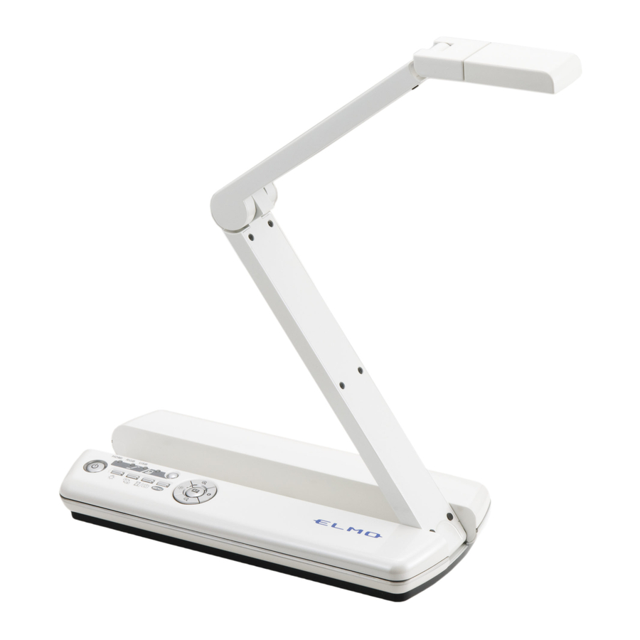
Page 12: 2 Part Names And Functions
2 PART NAMES AND FUNCTIONS Appearance Operation of the main unit: ① ④ ⑤ ⑦ ② ③ ⑧ ⑥ Name Camera head ① ② Operating panel ③ Rear panel ④ Side panel ⑤ Bottom panel ⑥ Lamp ⑦ Microphone ⑧... -
Page 13: Operating Panel
Operating panel ⑧ ⑭ ⑥ ⑬ ⑮ ⑫ ⑦ ⑪ ① ② ④ ③ ⑩ ⑨ ⑤ Mark Name Function To turn the power ON/OFF. Power Power ON : Blue light ① Power OFF (standby status) : Red light To turn the lamp ON/OFF Lamp ②... - Page 14 Mark Name Function To zoom in an object. Zoom In ⑧ N o t e The lamp is always OFF when power is turned on. 。 Zoom Out To zoom out an object. ⑨ Bright To brighten the camera image. ⑩...
-
Page 15: Rear Panel And Cable Connections
Rear panel and cable connections ⑥ ⑦ ① ② ③ ④ ⑤ Mark Function Name Security slot ① Plug-in for the AC adapter. ② Connect the supplied AC adapter. To connect the product to a PC. (USB cable is supplied with the ③... - Page 16 ・ Use a monitor that supports video signals (resolution) higher than 720p. The product does not operate with a cable that is not compliant with HDMI standard. ・ HDMI of the product is compliant with HDMI standard. Elmo does not guarantee operation of all HDMI-compatible monitors.
- Page 17 ⑦ To connect the product to a device with an HDMI output terminal. Connect a commercially available HDMI cable to the [HDMI IN] terminal on the rear panel. The product has a Standard HDMI (Type A) terminal. Press the Image Selection button to light up the Video Output LED [EXT]. N o t e •...
-
Page 18: Side Panel
Side Panel ① Function To insert an SD card (commercially available). ① Push the card again to remove the SD card. -
Page 19: Bottom Panel
Bottom panel ① Output resolution from the RGB OUT terminal can be changed with the dip switch. Change Resolution Function Switch MENU MENU Analog RGB output resolution can be changed from WXGA the OSD menu settings. MENU ① Analog RGB output resolution is fixed to XGA. WXGA MENU WXGA... -
Page 20: 3 Preparation And Connection
3 PREPARATION AND CONNECTION Setting Up N o t e ・Carry the product by holding the lower part of the body in both hands. Never hold the product by the arm or the camera head. ・Pay attention to prevent the camera head from knocking against a desk or the like. ・Move the arm while supporting the body with your hand. -
Page 21: Moving Parts Of The Mobile Document Camera
Moving Parts of the Mobile Document Camera This unit can be moved as shown below. 180° 180° 170° 150° Camera head 120° 180°... -
Page 22: Connecting To A Projector Or A Monitor
Connecting to a projector or a monitor Set up the product as shown in the above drawing and turn on the power after connecting a projector or a monitor. N o t e • Either an HDMI signal or an analog RGB signal can be output to a projector or a monitor. -
Page 23: Connecting To A Pc
Connecting to a PC Set up the product as shown in the above drawing and turn on the power after connecting a PC. -
Page 24: Turning On The Power
Turning on the power Power supply from the AC adapter 1. Connect the AC cord and the AC adapter. Then connect the AC adapter to the ] terminal at the rear panel of the product, and insert the AC cord into an outlet. -
Page 25: Shooting Images
4 SHOOTING IMAGES Adjusting the size The display range of the document can be adjusted by pressing the [ ] buttons on the operating panel. ]:ZOOM-IN・・・・・・The object can be shown in large size. ]:ZOOM-OUT・・・・The object can be shown in small size. N o t e Zoom ratio: Digital Max 8x. -
Page 26: Saving A Still Image
Saving a still image Press the [ ] button for long (more than 1 second) to save a still image to the SD card. Rotating the image ・Live image (Camera image): 【Upside▲】 mark in the camera head indicates the direction of the sensor. The image appears upside-down when the camera head is set as shown in the below drawing. -
Page 27: Switching The Output Video
Switching the output video The Video Output LED of the output terminal used is lit. The output video can be selected by pressing the Image Selection button. Video Output Function HDMI A video signal is output from the HDMI OUT terminal. ①... -
Page 28: In The Order That The Output Video Changes (In The Order That The Led Lights Up)
In the order that the output video changes (in the order that the LED lights up) Image Image Image Connected ① ② ③ Selection Selection Selection Item Button Button Button Power HDMI → → AC Adaptor → ① Power USB Cable →... -
Page 29: Changing The Settings
5 CHANGING THE SETTINGS Various settings for the product are changed through the menu (characters and icons) displayed on the screen. Changing the settings ① Press the [ ] button on the operating panel to display the menu on the screen, and then use the[ ] button to move the cursor to the icon you want to operate or set. -
Page 30: Descriptions Of Each Menu
Descriptions of each menu Camera output display mode menu Factory Icon Name Selection Item Function Setting To display the setting menu Preferences for the camera image. To display thumbnails of Thumbnails images saved in the SD card. Exit To hide the menu. Setting menu (Second layer) Factory Icon... - Page 31 Factory Icon Name Selection Item Function Setting To lower the fluorescent light flickering due to Japan/ power frequency. Flickerless 60Hz U.S. Select the same value as used for the power supply 50Hz Others frequency. The white balance is adjusted automatically to Auto ensure a more natural color ...
-
Page 32: Setting Date/Time(Clock Set
Factory Icon Name Selection Item Function Setting To format the SD card. (No operation is allowed Format during the formatting process.) Clock Set To set the time. To return to the camera Exit output display mode menu. N o t e When the output resolution is HDMI, actual output resolution might be different from the resolution set by the Setting menu depending on the connected monitor. -
Page 33: Using A Usb
6 USING A USB Installing the software Install the control software “Image Mate” contained in the supplied CD-ROM onto your PC to connect the product to a PC. For details about the operating environment and the OS of the connected computer or the operation of the software, refer to the installation manual of Image Mate. -
Page 34: Controlling The Product From A Usb-Connected Pc
Controlling the product from a USB-connected PC By using the “Image Mate”, you can perform the following tasks: ・To transfer the camera image to a PC ・To operate the product from a PC CAUTION ・Do not connect/disconnect the USB cable while operating the operating panel. ・We recommend using a USB 2.0-compliant USB cable. -
Page 35: Using An Sd Card
7 USING AN SD CARD With this product, you can save the camera image as a picture on an SD card. You can also display the data stored in the SD card on the screen. Before you begin, insert a commercially available SD card into the SD card slot of the side panel. -
Page 36: Saving Images
Saving images ① Press the [ ] button on the operating panel for 1 second or more while the menu is not displayed on the screen. ② Saving begins when [ ] appears on the screen. Displaying the saved data ①... -
Page 37: Thumbnail Display Mode
Thumbnail display mode Thumbnail display mode menu Factory Icon Name Selection Item Function Setting To display the camera Camera image. Still image display mode menu Factory Icon Name Selection Item Function Setting To display the camera Camera image. To delete the displayed still Delete image. -
Page 38: Trouble Shooting
8 TROUBLE SHOOTING If you have a problem or questions about this product, please read this troubleshooting guide first. If the problem still exists, consult the dealer from whom you purchased this product. Symptom Possible cause/ remedy No image is displayed. •... - Page 39 Symptom Possible cause/ remedy The image is striped. • This may be interference fringes between dots of the printed material and TV scanning lines or CMOS pixels. Changing the shooting range may help the problem. • Vertical stripes may appear on an LCD projector image. Manually adjusting the dot clock at the projector side may help the problem.
-
Page 40: Specifications
9 SPECIFICATIONS General Item Specifications DC5V(AC adapter AC100~240V) PC requirements for the power supply from a USB: - A PC with the USB3.0 port Power source - A PC with 2 USB ports Refer to P22 for details about the connection procedure. 4.2W(DC5.0V) Power consumption (USB Power Supply:3.3W) -
Page 41: Illumination Device
Item Specifications Limit of focus From lens surface 70mm~∞ adjustment Focus Auto/ Manual Image pick-up element 1/3.2” 5M pixel CMOS Sensor Effective pixels Horizontal 2048, Vertical 1536 Sync. system Internal HDMI output Image output 1080i, 720p(max Shooting area: 342mmx192mm) 720p (max Shooting area: 214mmx120mm) Analog RGB output 0.7V(p-p) WXGA:1280x800 @60Hz Analog RGB output... -
Page 42: Trademarks And License
• Repairable Period ELMO will maintain and keep spare parts for this product for eight years after the discontinuation of this product. After this period, ELMO will no longer offer repair service for this product. - Page 43 OVERSEAS SUBSIDIARY COMPANIES ELMO USA CORP. Headquarters 1478 Old Country Road Plainview, NY 11803-5034, U.S.A Tel:(516) 501-1400 Fax:(516) 501-0429 E-mail: elmo@elmousa.com Web: http://www.elmousa.com West Coast Branch Cypress Pointe Business Park 5676 Corporate Avenue Cypress, CA 90630, U.S.A Tel:(714) 828-8457 Fax:(714) 828-8429 ELMO Europe SAS Immeuble Elysées la Défense,...
Need help?
Do you have a question about the MO-1 and is the answer not in the manual?
Questions and answers