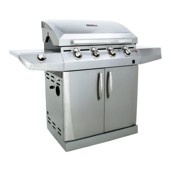
Char-Broil Performance T-47D Product Manual
463273112
Hide thumbs
Also See for Char-Broil Performance T-47D:
- Product manual (30 pages) ,
- Product manual (32 pages) ,
- Product manual (28 pages)
Advertisement
© 2011 Char-Broil, LLC Columbus, GA 31902
PRODUCT GUIDE
MODEL 463273112
Char-Broil Performance T-47D
IMPORTANT: Fill out the product record information below.
Serial Number
Date Purchased
For support and to register your
grill, please visit us at
www.charbroil.com
If you have questions or need
assistance during assembly,
please call 1-888-430-7870.
Printed in China
See rating label on grill for serial number.
Assembly instructions © 2011
11/07/11 • G520-001-210801
Advertisement
Table of Contents

Related Manuals for Char-Broil Char-Broil Performance T-47D


Summary of Contents for Char-Broil Char-Broil Performance T-47D
- Page 1 For support and to register your grill, please visit us at www.charbroil.com If you have questions or need assistance during assembly, please call 1-888-430-7870. © 2011 Char-Broil, LLC Columbus, GA 31902 Assembly instructions © 2011 Printed in China 11/07/11 • G520-001-210801...
-
Page 2: Table Of Contents
TABLE OF CONTENTS DANGER For Your Safety ........2-3 If you smell gas: Use and Care . - Page 3 WARNING CAUTION CALIFORNIA PROPOSITION 65 Using pots larger than 6 quarts in capacity could exceed weight limit of the 1. Combustion by-products produced when using this product contain chemicals known to the State of side burner shelf California to cause cancer, birth defects, and other or side shelf, reproductive harm.
-
Page 4: Use And Care
LP Cylinder USE AND CARE •The LP cylinder used with your grill must meet the following requirements: DANGER •Use LP cylinders only with these required measurements: 12" (30.5cm) (diameter) x 18" (45.7 cm) (tall) with 20 lb. (9 kg.) capacity maximum. •... -
Page 5: For Your Safety
LP Cylinder Exchange Connecting Regulator to the LP Cylinder •Many retailers that sell grills offer you the option of replacing 1.LP cylinder must be properly secured onto grill. (Refer to your empty LP cylinder through an exchange service. Use only assembly section.) those reputable exchange companies that inspect, precision fill, 2.Turn all control knobs to the OFF position. - Page 6 Leak Testing Valves, Hose and Regulator 1.Turn all grill control knobs to OFF. 2.Be sure regulator is tightly connected to LP cylinder. 3.Completely open LP cylinder valve by turning hand wheel counterclockwise. If you hear a rushing sound, turn gas off immediately.
- Page 7 Safety Tips WARNING Before opening LP cylinder valve, check the coupling nut for tightness. When grill is not in use, turn off all control knobs and LP cylinder valve. For Safe Use of Your Grill and to Avoid Serious Never move grill while in operation or still hot. Injury: Use long-handled barbecue utensils and oven mitts to avoid •...
- Page 8 Burner Flame Check Ignitor Lighting (continued) • Remove cooking grates and flame tamers. Light burners, rotate 8. For grills equipped with ELECTRONIC IGNITION at each burner: knobs from HI to LOW. You should see a smaller flame in Repeat steps 4 through 6 to light each burner. LOW position than seen on HI.
-
Page 9: Spider Alert
3. Remove carryover tubes and burners. CAUTION Detach electrode from burner. NOTE: Removal/Detachment method will depend on the SPIDER ALERT! burner configuration. See different configurations in illustrations below. 5. Carefully lift each burner up and away from valve openings. We suggest three ways to clean the burner tubes. Use the one SPIDER AND WEBS easiest for you. -
Page 10: Limited Warranty
LIMITED WARRANTY This warranty only applies to units purchased from an authorized retailer. Manufacturer warrants to the original consumer-purchaser only that this product shall be free from defects in workmanship and materials after correct assembly and under normal and reasonable home use for the periods indicated below beginning on the date of purchase*. -
Page 11: Parts List
PARTS LIST Key Qty Description Key Qty Description RUBBER BUMPER, RECTANGLE, F/ BOTTOM SHELF TOP LID TANK SCREW, F/ BOTTOM SHELF HEAT SHIELD F/ TANK CASTER, LOCKING TEMPERATURE GAUGE, UFC CASTER, FIXED MOUNTED CART LEFT SIDE PANEL LOGO PLATE GROMMET, F/ REGULATOR HOLE HARDWARE F/ TOP LID ASSEMBLY CART RIGHT SIDE PANEL LEFT DOOR, NO HANDLE... -
Page 12: Parts Diagram
PARTS DIAGRAM... -
Page 13: Assembly
ASSEMBLY Place bottom shelf upside down. Insert Caster Pin into the caster mounting plate to lock it in place, shown A. Spin the caster clockwise into the threads on the bottom shelf until secure. Remove the Caster Pin and repeat for remaining casters. - Page 14 Place lower back panel between side panels at rear of bottom shelf. Make sure the slots noted in the view (A) below are positioned as shown. Secure lower back panel to side panels using two 1/4-20x1/2” screws, 7mm lock washers, and 7mm flat washers on each side.
- Page 15 On back of grill, place upper back panel between side panels and above lower back panel. Secure upper back panel, in lower hole, using one 1/4-20x1½” screw, 7mm lock washer, and 7mm flat washer on each side. Do not fully tighten screws until side shelf installation is complete in later steps. Upper back panel 7mm flat 1/4-20x1½”...
- Page 16 NOTE: DO NOT over tighten screws and washers that come into contact with porcelain coated surfaces. Over tightening may cause the porcelain coating to crack and break, resulting in exposed metal that will be prone to rust. Insert flange on right side shelf into side shelf brackets on side of firebox. Attach right side shelf using three 1/4-20x3/4”...
- Page 17 Insert flange on left sideburner shelf into side shelf brackets on side of firebox. Attach left sideburner shelf using three 1/4-20x3/4” screws, 7mm lock washers, 7mm flat washers, 1/4” nuts, shown A. screw, 7mm lock washer, and 7mm Attach rear of shelf using one flat washer in lower hole, shown B.
- Page 18 Insert front brace under control panel and between cart side panels. Make sure door hinge pins are on the top side and facing the front. Secure using two 1/4-20x1½” screws, 7mm lock washers, and 7mm flat washers on each side. 1/4-20x1½”...
- Page 19 Insert sideburner into left shelf. The stud on bottom of burner fits into rear small hole in sideburner drip pan on shelf, shown A. Secure burner to sideburner drip pan with one Wing nut, shown B. Make sure burner tube engages sideburner valve, shown C.
- Page 20 Inside of cart, insert rear tabs (without holes) of tank heat shield into three slots between upper and lower back panels, shown A. Attach front tabs of tank heat shield under front brace with three #8x3/8” self-tapping screws, shown B. Insert left and right grease tray rails into slots beneath greas tray opening in rear upper panel.
- Page 21 Inside of cart, insert tank exclusion wire ends into lower back panel. Attach front right side of wire shelf to the right side panel with one #8-32x3/8” screw, 4mm lock washer and 4mm flat washer, shown A. Leg attaches to bottom shelf with screw, one #8-32x3/8”...
- Page 22 Inside of cart, connect each of the wires from the main burner electrodes, and sideburner electrode into the back of the electronic ignition module. Total (5) connections. Connect the two wires {(a) and (b)} from the switch wiring harness into the back of the electronic ignition module.
- Page 23 Insert hinge pin on bottom of doors into hole in bottom shelf. Press upper hinge pin in front brace, align hinge hole on top of door, and release hinge pin into door. PRESS Top of door Right door Hinge pin on bottom of door Install flame tamers by sliding one end of each flame tamer into slots at front of firebox and resting opposite end on pins in...
- Page 24 Place cooking grates onto the firebox as shown. Insert the two wire ends at rear of warming rack into holes in back of firebox. Front wires of warming rack rest on sides of firebox. Cooking grate On back of grill, slide grease tray into opening in upper back panel. CAUTION Failure to install grease tray will cause hot grease to drip from bottom...
- Page 25 LP CYLINDER IS SOLD SEPARATELY. Fill and leak check the cylinder before attaching to grill and regulator (see Use & Care section). Once cylinder has been filled and leak checked, place cylinder into hole in bottom shelf. Make sure cylinder valve is facing front of grill.
-
Page 26: Troubleshooting
DANGER: If a gas leak cannot be stopped, or a fire occurs due to gas leakage, call the fire department. Emergencies Possible Cause Prevention/Solution Gas leaking from • Damaged hose. • Turn off gas at LP cylinder or at source on natural gas systems. If cracked/cut/burned anything but burned, replace valve/hose/regulator. - Page 27 Troubleshooting (continued) Problem Possible Cause Prevention/Solution Burner(s) will not light ELECTRONIC IGNITION: using ignitor. • No spark, no ignition noise. • See Section I of Electronic Ignition System. (See Electronic Ignition Troubleshooting also) • No spark, some ignition noise. • See Section II of Electronic Ignition System. •...
- Page 28 Troubleshooting - Electronic Ignition Problem (Ignition) Possible Cause Check Procedure Prevention/Solution SECTION I No sparks appear at • Battery not installed • Check battery orientation. • Install battery (make sure that “+” and “–” any electrodes when properly. connectors are oriented correctly, with “+” end up Electronic Ignition Button and “–”...
- Page 29 NOTES...
- Page 30 NOTES...
Need help?
Do you have a question about the Char-Broil Performance T-47D and is the answer not in the manual?
Questions and answers