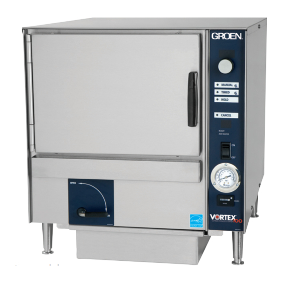
Groen VRC-3E Service Manual
Connectionless steamer
Hide thumbs
Also See for VRC-3E:
- Service manual (61 pages) ,
- Operator's manual (23 pages) ,
- Brochure (2 pages)
Table of Contents
Advertisement
SERVICE MANUAL
IMPORTANT INFORMATION, KEEP FOR OPERATOR
This manual provides information for:
MODELS VRC-3E
& VRC-6E
VORTEX100
CONNECTIONLESS
STEAMER
· Self Contained
· Electric Heated
· Capacity:
VRC-3E=3 Steamer Pans Per Cavity
VRC-6E=6 Steamer Pans Per Cavity
Information contained in this document is known to be current and accurate at the time
of printing/creation. Unified Brands recommends referencing our product line websites,
unifiedbrands.net, for the most updated product information and specifications.
PART NUMBER 145702, REV. C (01/07)
Domestic
®
1055 Mendell Davis Drive
Jackson, MS 39272
888-994-7636, fax 888-864-7636
groen.com
Advertisement
Table of Contents

Related Manuals for Groen VRC-3E


Summary of Contents for Groen VRC-3E
- Page 1 STEAMER · Self Contained · Electric Heated · Capacity: VRC-3E=3 Steamer Pans Per Cavity VRC-6E=6 Steamer Pans Per Cavity 1055 Mendell Davis Drive Information contained in this document is known to be current and accurate at the time Jackson, MS 39272 of printing/creation.
-
Page 2: Table Of Contents
Table of Contents INTRODUCTION Page THE GROEN SERVICE CONCEPT ..................5 THE GROEN CERTIFIED SERVICE..................5 WARRANTY AND NON-WARRANTY REPAIRS ..............SAFETY ..........................5-6 GLOSSARY OF TERMS ......................6 TOOLS AND SUPPLIES ......................6 1.6.1 Reqired Tools ......................6 1.6.2 Recommended Instruments..................6 1.6.3 Helpful Hardware .................... - Page 3 Table of Contents ASSEMBLY / DISASSEMBLY Page AIR TEMPERATURE PROBE....................21 CAVITY VENT ASSEMBLY ....................22 CONTROL PC BOARD ......................22 DOOR REMOVAL/INSTALLATION/ALIGNMENT ..............22 DOOR SWITCH ........................23 DOOR REVERSING PROCEDURE ..................23 DOOR GASKET ........................23-24 DOOR SPRING........................24 DOOR LOCKING PIN AND LOCK ..................
- Page 4 Table of Contents PARTS IDENTIFICATION • VRC-3E Page CAVITY VENT ASSEMBLY ....................32 CONTROL BOARD AND WIRING HARNESSES ..............33 DOOR ASSEMBLY........................ 34 ELECTRICAL COMPONENTS 208/240/240 VOLTS..............35 HEATER ELEMENTS......................36 MOTOR ASSEMBLY......................37 FLOAT ASSEMBLY ....................... 38 INTERIOR & EXTERIOR CABINET..................39 PARTS IDENTIFICATION •...
-
Page 5: The Groen Service Concept
ANSI 535 Standard. Three different signal words alert you to a • Groen certifies that this manual will be updated by means of hazardous situation: DANGER, WARNING, AND CAUTION periodic service bulletins to provide the most up-to-date DANGER: The signal word DANGER indicates that a information for field maintenance and service personnel. -
Page 6: Safety
INTRODUCTION 1.6 Tools and Supplies WARNING: The signal word WARNING tells you that a possibly hazardous situation is about to take place which, if not avoided, could cause death or serious injury. This Section identifies the tools, instruments and supplies which •... -
Page 7: Recommended Supplies
1.6.4 Recommended Supplies 1.7.1 Technical Bulletins • Pipe Thread Compound: Brand: LACO PipeTite Stik Technical bulletins are issued by Groen to provide additional and No. 11176 or equivalent specific technical information to this manual. The technical • Motor Sealant Grease: Bel-Ray Bulletin Section of this manual should be used to file all of the •... - Page 8 TECHNICAL BULLETINS 1.7.1a PART NUMBER 145702, REV. B (7/06) CALL 888-994-7636 FOR TECHNICAL SUPPORT PART NUMBER 145702, REV. C (01/07) Call 1-800/676-9040 for Technical Support...
-
Page 9: Operation
OPERATION 2.1 Controls Operator controls are on the front right of the unit. The VRC-3E and VRC-6E control panels have the following touch pads and indicator lights: TIME display • The ON/OFF rocker switch gets the Vortex ready for use, TIMER knob or shuts it off. -
Page 10: Operating Procedure
OPERATION 2.2 Operating Procedure 6. To remove pans from cavity, open the door. Remove the 1. Push the ON switch and make sure drain handle is in the pans from the steamer, using hot pads or oven mitts to closed position. 2. -
Page 11: Installation
Electrical Supply Connection – Observe all local, national, or 60 hz only Demand (amps) other applicable codes. VRC-3E VRC-6E 9KW 6.76KW 12KW 10KW 9KW Three phrase models of the Vortex100 Connectionless Steamer are supplied with a cord set ready to be connected to a power supply. -
Page 12: Installation
INSTALLING, CLEANING AND TESTING Water Connections(s) Stacking Units Instructions • Units with Manual Fill Remove drain containment pan from the bottom of unit(s). No water connection is needed. The water will be poured directly Unscrew to remove adjustable legs from base of Vortex unit(s). into the water cavity reservoir. -
Page 13: Installation Checklist
INSTALLING, CLEANING AND TESTING 3.2 Installation Checklist 3.3 Cleaning General To keep your VRC-3E or VRC-6E Connectionless Steamer in proper working condition, use the following procedure to clean the unit. _____ Remove all packaging. A. Suggested Tools _____ Make sure there is a minimum of 2 inches of free space around the steamer. - Page 14 INSTALLING, CLEANING AND TESTING WARNING Keep water and cleaning solutions out of controls and electrical components. Never hose or steam clean any part of the unit. Even when the unit has been shut off, don’t put hands or tools into the cooking chamber until the fan has stopped turning.
- Page 15 INSTALLING, CLEANING AND TESTING Notes CALL 888-994-7636 FOR TECHNICAL SUPPORT PART NUMBER 145702, REV. B (7/06) PART NUMBER 145702, REV. C (01/07) Call 1-800/676-9040 for Technical Support...
-
Page 16: Troubleshooting Procedures & Quick Reference
TROUBLESHOOTING 4.1 Vortex100 Troubleshooting Procedure Each test procedure builds on the prior ones. Always start at the beginning of this procedure, and continue until the results indicate a malfunction. Do not skip steps. WARNING: Disconnect electrical power before servicing. SETUP EXPECTED RESULTS PROBABLE DEFECT TEST or COMMENTS... - Page 17 TROUBLESHOOTING SETUP EXPECTED RESULTS PROBABLE DEFECT TEST or COMMENTS Factory optional water fill kit. Water fills to high water float High water float Use sensor diagnostics Close door. Water fill solenoid valve Use 02 diagnostic to test valve Incorrect wiring Check per wiring diagram Control or relay board Substitute to test...
- Page 18 TROUBLESHOOTING SETUP EXPECTED RESULTS PROBABLE DEFECT TEST or COMMENTS Look for temperature rise on the Heats to 200 + degrees in Heater element Measure amperage for each dial temperature guage 22 +/- 5 minutes leg and compare to the chart on next page.
- Page 19 480* Three Phase 14.4 19.2 23.0 VRC-6E 208 Single Phase 10.8 13.0 14.4 VRC-6E 240 Single Phase 14.4 17.3 19.2 VRC-3E 208 Three Phase 14.4 19.2 VRC-3E 240 Three Phase 19.2 VRC-3E 480* Three Phase 10.8 VRC-3E 208 Single Phase 14.4 19.2...
-
Page 20: Vrc Checkout
TROUBLESHOOTING 4.2 VRC Checkout SETUP EXPECTED RESULTS PROBABLE DEFECT TEST or COMMENTS 1. Apply power to the VRC. On the back of the front-panel control Reconnect the terminal. The Heater Overtemp (top) bar should board, flip the left DIPswitch up to start the diagnostics. go out. -
Page 21: Air Temperature Probe
ASSEMBLY / DISASSEMBLY WARNING Be sure the steamer is disconnected from the branch circuit power before performing any repair work. 5.1 Air Temperature Probe Installation 7. If the air probe guard is not in place, one will have to be installed. -
Page 22: Cavity Vent Assembly
4. Remove the hose from the hose fittings. 5.4 Door Removal/lnstallation/Alignment 5. Unscrew the assembly from the nipple attached to the cavity. P/N 130858 Door Assembly for VRC-3E Installation P/N 140749 Door Assembly for VRC-6E 6. Thread the new assembly onto the nipple attached to the cavity. -
Page 23: Door Switch
Install these two items 5.7 Door Gasket so that the lock nut to end of the bullet distance is P/N 124849 VRC-3E approximately the same as measured in step 4. P/N 140748 VRC-6E 7. Remove the two screws from above and below the old... -
Page 24: Door Spring
ASSEMBLY / DISASSEMBLY 5.9 Door Locking Pin Installation 7. Apply a RTV 732 or equivalent, to the door spacers. P/N 078914 Door Locking Pin 8. Install the new door gasket around the outer door panel on P/N 003823 Lock Nut the insulation board. -
Page 25: Fan
P/N 142355 208 Volts 9 KW VRC-6E P/N 142500 240 Volts 9 KW VRC-6E P/N 141075 208 Volts 9 KW VRC-3E P/N 141079 240 Volts 9 KW VRC-3E P/N 141080 480 Volts 9 KW VRC-3E P/N 141079 208 Volts 6.76 KW... -
Page 26: Hi-Limit Thermostat
ASSEMBLY / DISASSEMBLY Installation 16. Place the lower aluminum heat sink plate on the element. 12. Assemble the plate assembly DRY to be sure the orientation This plate has orientation studs. Carefully adjust the of the assembly is correct and the correct sides of the plates element so the orientation studs do not sit on the are marked. -
Page 27: Motor, Fan Assembly
ASSEMBLY / DISASSEMBLY 5.15 Fan Motor Assembly P/N 096740 Fan Motor IMPORTANT P/N 096868 Motor Shaft Seal The oil slinger washer has a rubber P/N 096831 Oil Slinger Washer surface and a phenolic surface. Make sure the phenolic surface is Removal facing the motor. -
Page 28: Motor, Starting Capacitor
ASSEMBLY / DISASSEMBLY 5.16 Motor Starting Capacitor - P/N096813 5.18 Right Side Panel and Left Side Panel P/N 140447 Right Side Panel VRC-3E Removal P/N 140448 Left Side Panel VRC-3E 1. Turn off the steamer power and disconnect the steamer P/N 140761 Right Side Panel VRC-6E from the branch circuit. -
Page 29: Remote Reading Thermometer
ASSEMBLY / DISASSEMBLY 5.20 Remote Reading Thermometer 5.21 Water Level Float P/N 141055 Remote Reading Thermometer Removal 1. Turn off the steamer power and disconnect the steamer Removal from the branch circuit. 1. Turn off the steamer power and disconnect the steamer 2. -
Page 30: Water Drain Kit Installation
ASSEMBLY / DISASSEMBLY 5.22 WATER DRAIN KIT INSTALLATION 1. Remove all parts from shipping cartons. 3.5 A 10ft piece of hose is supplied with this kit, it can be cut 2. Check-identify all parts as follow. to length and used with the elbow to help route the hose 2.1 Water Drain Parts to the proper drain location. - Page 31 ASSEMBLY / DISASSEMBLY ATTACH HOSE 143254 (3/8" DIAMETER X 30"LONG) Item # Part # Description TO THIS PORT USING THE TENSION CLAMP. 142549 Elbow, 3/4 ” Hose Barb 141067 Chamber Assembly. Reference only 142550 Tee, 3/4” Hose Barb 140789 Back Panel - Reference Only. 143246 Drain Assembly, Autodrain Kit 143250...
-
Page 32: Cavity Vent Assembly
PARTS IDENTIFICATION • VRC-3E 6.1 Cavity Vent Assembly Description Qty. Part No. Pressure Relief Valve 1/2 PSI 140867 (Remove used plug if needing to replace) Kit Motor Assembly 14688OS Exhaust Assembly 141512 Constant Tension Band 127524 Clamp, Constant Tension 127523 Condensate Hose 9”... -
Page 33: Control Board And Wiring Harnesses
PARTS IDENTIFICATION • VRC-3E 6.2 Control Board and Wiring Harnesses Description Qty. Part No. Harness, VRC Control to 160879 Relay Board Motor 1/15HP 2-Pole 096739 Harness, VRC Low Voltage 160875 Harness, Steamer High Voltage 160874 Harness, VRC Forward 160876 Harness, VRC RTD to Control Board... -
Page 34: Door Assembly
PARTS IDENTIFICATION • VRC-3E 6.3 Door Assembly (130858) Description Qty. Part No. Outer Door Panel 130895 Gasket 124849 Inner Door Panel 130861 Truss Head Screws 005764 Hex Head Screws 005608 Door Handle 129723 Door Hinge 140755 Door Cam 074252 Latch Assembly... -
Page 35: Parts Identification Vrc-3E
PARTS IDENTIFICATION VRC-3E 6.4 Electrical Components 208/240/480 Volts No. Description Qty. Part No. High Voltage Panel 160488 Transformer, 75VAC 121716 Contactor, 3-Pole 144418 Capacitor Foil 3 Mfd 096813 Screw Hex Slotted Washer Head Cap 069789 Screw Round Head 8-32 1 1/4”... -
Page 36: Heater Elements
PARTS IDENTIFICATION • VRC-3E 6.5 Heater Element Assembly Description Qty. Part No. Heater Element Replacement Kit 143320 208 volts 9 KW Heater Element Replacement Kit 143321 240 volts 9 KW Heater Element Replacement Kit 143322 480 volts 9 KW Heater Support Bracket... -
Page 37: Motor Assembly
PARTS IDENTIFICATION • VRC-3E 6.6 Motor Assembly Description Qty. Part No. Motor Assembly (Kit) 14688OS Motor Insulator 094135 Motor Shaft Seal 096868 Keps Nut 1/4”-20 012940 Blower Wheel (Fan) 096790 Set Screw 096789 *Not shown PART NUMBER 145702, REV. B (7/06) CALL 888-994-7636 FOR TECHNICAL SUPPORT PART NUMBER 145702, REV. -
Page 38: Float Assembly
PARTS IDENTIFICATION • VRC-3E 6.7 Float Assemblies Description Qty. Part No. Cavity Air Temperature Probe 085187 Probe Protector Assembly 074827 Compression Nut 1/8” 071284 Probe Male Fitting 071217 Remote Reading Thermometer 141055 Temperature Gauge Bulb Fitting 141058 Jam Nut 3/4 ”-16 141056 Fiber Washer 3/4 ”... -
Page 39: Interior & Exterior Cabinet
PARTS IDENTIFICATION • VRC-3E Interior and Exterior Cabinet Description Qty. Part No. Blower wheel 096790 Blower cover assembly 139773 Left side rack 124873 Water Level Float 142689 PART NUMBER 145702, REV. B (7/06) CALL 888-994-7636 FOR TECHNICAL SUPPORT PART NUMBER 145702, REV. C (01/07) -
Page 40: Parts Identification • Vrc-6E
PARTS IDENTIFICATION • VRC-6E 7.1 Cavity Vent Assembly Description Qty. Part No. Pressure Relief Valve 1/2 PSI 140867 (Remove used plug if needing to replace) Kit Motor Assembly 14688OS Exhaust Assembly 141512 Constant Tension Band 127524 Clamp, Constant Tension 127523 Condensate Hose 9”... -
Page 41: Control Board And Wiring Harnesses
PARTS IDENTIFICATION • VRC-6E 7.2 Control Board and Wiring Harnesses Description Qty. Part No. Harness, VRC Control to 160879 Relay Board Motor 1/15HP 2-Pole 096739 Harness, VRC Low Voltage 160875 Harness, Steamer High Voltage 160874 Harness, VRC Forward 160876 Harness, VRC RTD to Control Board 160878 Harness, VRC Auto-Fill 160877... -
Page 42: Door Assembly
PARTS IDENTIFICATION • VRC-6E 7.3 Door Assembly (140749) Description Qty. Part No. Outer Door Panel 140750 Gasket 140748 Inner Door Panel 140751 Truss Head Screws 005764 Hex Head Screws 005608 Door Handle 129723 Door Hinge 140755 Door Cam 074252 Latch Assembly 140752 Door Spacers 071206... -
Page 43: Electrical Components 208/240/480 Volts
PARTS IDENTIFICATION • VRC-6E PARTS IDENTIFICATION 7.4 Electrical Components 208/240/480 Volts No. Description Qty. Part No. High Voltage Panel 160488 Transformer, 75VAC 121716 Contactor, 3-Pole 144418 Capacitor Foil 3 Mfd 096813 Screw Hex Slotted Washer Head Cap 069789 Screw Round Head 8-32 1 1/4” 005056 Nut Lock 6-32 119855... -
Page 44: Heater Elements
PARTS IDENTIFICATION • VRC-6E 7.5 Heater Element Assembly Description Qty. Part No. Heater Element Replacement Kit 143323 208 volts 9 KW Heater Element Replacement Kit 143324 240 volts 9 KW Heater Element Replacement Kit 143325 480 volts 9 KW Heater Support Bracket 142561 Heater Support Bracket 143037... -
Page 45: Motor Assembly
PARTS IDENTIFICATION • VRC-6E 7.6 Motor Assembly Description Qty. Part No. Motor Assembly (Kit) 14688OS Motor Insulator 094135 Motor Shaft Seal 096868 Keps Nut 1/4”-20 012940 Blower Wheel (Fan) 096790 Set Screw 096789 *Not shown PART NUMBER 145702, REV. B (7/06) CALL 888-994-7636 FOR TECHNICAL SUPPORT PART NUMBER 145702, REV. -
Page 46: Float Assemblies
PARTS IDENTIFICATION • VRC-6E 7.7 Float Assemblies Description Qty. Part No. Cavity Air Temperature Probe 085187 Probe Protector Assembly 074827 Compression Nut 1/8” 071284 Probe Male Fitting 071217 Probe Nut 7/16”-28 070452 Probe Washer 071253 Fiber Washer 071252 Probe Fitting 071231 Remote Reading Thermometer 141055... -
Page 47: Interior & Exterior Cabinet
PARTS IDENTIFICATION • VRC-6E 7.8 Interior and Exterior Cabinet Description Qty. Part No. Blower wheel 096790 Blower cover assembly 140785 Left side rack 140782 Water Level Float 142689 PART NUMBER 145702, REV. B (7/06) CALL 888-994-7636 FOR TECHNICAL SUPPORT PART NUMBER 145702, REV. C (01/07) Call 1-800/676-9040 for Technical Support... -
Page 48: Specifications • Vrc-3E, Vrc-6E
SPECIFICATIONS • VRC-3E, VRC-6E Electrical Specifications General Specifications Electrical requirement are, 208, 240 or 480 volts, single Atmospheric Steamer (208 or 240 volts steamers) or three phase power supply. Note: 480-volt steamers are three phase only. The Vortex100 Connectionless Steamer has an electric heated water... -
Page 49: Wiring Diagram
WIRING DIAGRAM • VRC-3E, VRC-6E Single Contractor Versions 24VAC 208V 240V 24VAC BOARD RELAY 160649 BOARD CONTROL STEAMER J5A1 160648 BOARD CONTROL BLACK BLACK BLACK ACHI BLACK ORANGE LEFT 10VAC ORANGE ORANGE RIGHT ORANGE BLACK WHITE SWITCH DOOR GREEN BOARD... -
Page 50: Ladder Diagram
WIRING DIAGRAM • VRC-3E, VRC-6E LADDER DIAGRAM Single Contractor Versions 24VAC 208V 240V 24VAC BOARD CONTROL STEAMER J5A1 ACHI BLACK LEFT 10VAC RIGHT BLACK WHITE SWITCH DOOR 10VAC BLUE ACLO BLUE 24(DONE) BLUE 22(TIMING) BLUE BLUE BLUE 12(MANUAL) BLUE PART NUMBER 145702, REV. B (7/06) CALL 888-994-7636 FOR TECHNICAL SUPPORT PART NUMBER 145702, REV. - Page 51 INSTALLING, CLEANING AND TESTING Notes CALL 888-994-7636 FOR TECHNICAL SUPPORT PART NUMBER 145702, REV. B (7/06) PART NUMBER 145702, REV. C (01/07) Call 1-800/676-9040 for Technical Support...
- Page 52 1055 Mendell Davis Drive • Jackson MS 39272 888-994-7636 • 601-372-3903 • Fax 888-864-7636 groen.com PART NUMBER 145702, REV. C (01/07)
Need help?
Do you have a question about the VRC-3E and is the answer not in the manual?
Questions and answers