Table of Contents
Advertisement
Copyright
All rights are reserved. No part of this publication may be reproduced, transmitted, transcribed, stored in a
retrieval system or translated into any language or computer language, in any form or by any means,
electronic, mechanical, magnetic, optical, chemical, manual or otherwise, without the prior written
permission of the company. Brands and product names are trademarks or registered trademarks of their
respective companies.
The vendor makes no representations or warranties with respect to the contents herein and especially
disclaim any implied warranties of merchantability or fitness for any purpose. Further the vendor reserves
the right to revise this publication and to make changes to the contents herein without obligation to notify
any party beforehand. Duplication of this publication, in part or in whole, is not allowed without first
obtaining the vendor's approval in writing.
Trademark
All the trademarks or brands in this document are registered by their respective owner.
Disclaimer
We make no warranty of any kind with regard to the content of this user's manual. The content is subject
to change without notice and we will not be responsible for any mistakes found in this user's manual. All
the brand and product names are trademarks of their respective companies.
FCC Compliance Statement
This equipment has been tested and found to comply with the limits of a Class B digital device, pursuant to
Part 15 of the FCC Rules. These limits are designed to provide reasonable protection against harmful
interference in a residential installation. This equipment generates, uses and can radiate radio frequency
energy and, if not installed and used in accordance with the instructions, may cause harmful interference
to radio communications. Operation of this equipment in a residential area is likely to cause harmful
interference in which case the user will be required to correct the interference at his own expense.
However, there is no guarantee that interference will not occur in a particular installation.
CE Mark
The device is in accordance with 89/336 ECC-ENC Directive.
Ver: EG100
PXP35 (V2.0)
Advertisement
Table of Contents

Related Manuals for Albatron PXP35 (V2.0)


Summary of Contents for Albatron PXP35 (V2.0)
-
Page 1: Fcc Compliance Statement
PXP35 (V2.0) Copyright All rights are reserved. No part of this publication may be reproduced, transmitted, transcribed, stored in a retrieval system or translated into any language or computer language, in any form or by any means, electronic, mechanical, magnetic, optical, chemical, manual or otherwise, without the prior written permission of the company. - Page 2 PXP35 (V2.0) ® Intel P35 & ICH7 ® Support Socket 775 Intel Core 2 Quad/ ® Core 2 Extreme/ Core 2 Duo/ Pentium ® ® Pentium 4/Celeron Processors User Manual Dimensions (ATX form-factor): 220 mm x 305 mm ( W x L ) Operating System: ®...
-
Page 3: Packing List
Things You Have To Know The images and pictures in this manual are for reference only and may vary from the product you received depending on specific hardware models, third party components and software versions. This mainboard contains very delicate IC chips. Always use a grounded wrist strap when working with the system. -
Page 4: Table Of Contents
Table of Contents CHAPTER 1. GETTING STARTED ..............1 ....................... 1 NTRODUCTION ....................... 2 PECIFICATION ....................5 ONFIGURATION Layout of PXP35 (V2.0).................. 5 ................... 6 ARDWARE NSTALLATION CPU Processor Installation................6 Memory Installation: DIMM1/2/3/4..............7 Back Panel Configuration................9 Connectors..................... 11 Front Panel Headers: JW_FP, PWRLED, SPEAK ........ -
Page 5: Chapter 1. Getting Started
Mainboard PXP35 (V2.0) Chapter 1. Getting Started Introduction ® Thanks for choosing PXP35 (V2.0) Mainboard. It is based on Intel P35 Northbridge chipset ® ® and Intel ICH7 Southbridge chipset. It supports Intel Core 2 Quad/ Core 2 Extreme/ ® ®... -
Page 6: Specification
Mainboard PXP35 (V2.0) Specification CPU: Support Socket 775 ® ® Support Intel Core 2 Quad/ Core 2 Extreme/ Core 2 Duo/ Pentium ® ® Pentium 4/ Celeron Processors Support Hyper-Threading Technology Support 1333 MHz/ 1066 MHz/ 800 MHz FSB (Front Side Bus) Frequencies Chipset: ®... -
Page 7: Fdd Connector
Mainboard PXP35 (V2.0) Two PCI-E x1 slots: support up to x1 mode Three PCI interface slots for expansion cards FDD Connector: Supports one FDD connector to set up to two floppy disk drives Supports 360KB/ 720KB/ 1.2MB/ 1.44MB/ 2.88MB IDE Connector: One IDE connector Supports up to two IDE devices Supports Ultra ATA 33/66/100... -
Page 8: Flash Memory
Mainboard PXP35 (V2.0) BIOS: Phoenix-Award™ BIOS Support APM 1.2 Support ACPI 2.0 power management Green Function: Supports Phoenix-Award™ BIOS power management function Supports system-wake-from-power-saving-mode by keyboard or mouse touching Shadow RAM: Integrated memory controller provides shadow RAM functionality and supports ROM BIOS Flash Memory: Supports flash memory functionality... -
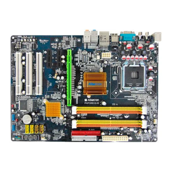
Page 9: Configuration
Mainboard PXP35 (V2.0) Configuration Layout of PXP35 (V2.0) -
Page 10: Hardware Installation
Mainboard PXP35 (V2.0) Hardware Installation This section will assist you in quickly installing your system hardware. Wear a wrist ground strap before handling components. Electrostatic discharge may damage the system’s components. CPU Processor Installation ® ® ® This mainboard supports Intel Core 2 Quad/ Core 2 Extreme/ Core... -
Page 11: Memory Installation: Dimm1/2/3/4
Mainboard PXP35 (V2.0) FAN Headers: CPUFAN, SYSFAN1, SYSFAN2 There are three fan headers available for cooling fans. The cooling fans play an important role in maintaining ambient temperatures in your system. The CPUFAN header is attached with a CPU cooling fan. - Page 12 Mainboard PXP35 (V2.0) How to enable Dual-Channel DDRII: This mainboard provides Dual-Channel functionality for the four DIMM sockets. Enabling Dual-Channel will significantly increase your data access rate than the before. DIMM1 and DIMM3 share one channel, and DIMM2 and DIMM4 share another channel. To enable Dual-Channel, you need to install memories in the same channel of DIMM sockets.
-
Page 13: Back Panel Configuration
Mainboard PXP35 (V2.0) * The pictures above are for reference only. Your actual installation may vary slightly from the pictures. Back Panel Configuration PS/2 Mouse & PS/2 Keyboard Ports: KB/MS This mainboard provides a standard PS/2 mouse port and a PS/2 keyboard port. The Serial Port: COM1 This mainboard provides a serial port COM1 on your back panel, and is used to connect mice, modem and other peripheral devices. - Page 14 Mainboard PXP35 (V2.0) Audio Ports: SOUND This mainboard provides six HD Audio ports for 8/6/4/2 channel playback capability. With jack sensing, auto detecting and adjusting, the device will make it easier to Plug and Play for you. Line-In (blue) This port is for audio input and connects to external audio devices such as CD player, tape player or other audio devices when the 8/6/4/2 channel audio effects driver is enabled.
-
Page 15: Connectors
Mainboard PXP35 (V2.0) Connectors Floppy Disk Drive Connector: FLOPPY The mainboard provides a standard floppy disk drive connector (FDD) that supports 360KB/720KB/ 1.2MB/1.44MB/2.88 MB floppy disk drives using a FDD ribbon cable. Hard Disk Drive Connector: IDE The mainboard provides one IDE connector that supports Ultra ATA 100/ 66/ 33 IDE devices. You can attach a maximum of two IDE devices, such as hard disk drive (HDD), CD-ROM, DVD-ROM, etc. -
Page 16: Front Panel Headers: Jw_Fp, Pwrled, Speak
Mainboard PXP35 (V2.0) Front Panel Headers: JW_FP, PWRLED, SPEAK JW_FP Assignment Function Assignment Function VCC5 (+) VCC5 (+) Hard Drive LED 2-pin Power LED (HDLED) (PWRLED) HDDLE (-) PWRLED (-) PWRBTN Power-on Button Reset Switch (PWRBTN) RSTSW (RESET) Hard Drive LED Header: HDLED If your case front panel has a hard drive LED cable, attach it to this header. -
Page 17: Headers & Jumpers
Mainboard PXP35 (V2.0) Assignment Assignment PWR_LED (+) PWRLED PWR_LED (-) Speaker Header: SPEAK A speaker cable on your case front panel can be attached to this header. When you reboot the computer, this speaker will issue a short audible (beep). If there are problems during the Power On Self-Test, the system will issue an irregular pattern of audible beeps through this speaker. - Page 18 Mainboard PXP35 (V2.0) Front USB Headers: USB2/ USB3 This mainboard provides four onboard USB 1.1/2.0 ports (back panel) that attach to USB devices. There are two additional USB headers that can be connected by cables to four more USB ports on the front panel of your case giving you a possible eight USB ports.
- Page 19 Mainboard PXP35 (V2.0) USB Power On function Header: JP3/ JP4 USB devices attached to the back panel USB ports can awaken the system from sleep mode. In order to enable this functionality, you must adjust the jumper caps on JP3/ JP4 header for +5V or +5VSB mode depending on which USB port that the USB device is attached to.
-
Page 20: Audio Configuration
Mainboard PXP35 (V2.0) Audio Configuration CD-ROM Audio-In Header: CDIN The CD-IN connector is used to attach an audio cable to audio devices such as CD-ROMs, DVD-ROMs etc. HDMI-SPDIF out Header: HDMI-SPDIF (Optional) The SPDIF output is capable of providing digital audio to external speakers or compressed AC3 data to an external Dolby digital decoder. -
Page 21: Slots
Mainboard PXP35 (V2.0) Slots PCI-Express x16 Interface slot: PE1 The PE1 slot is the PCI-Express x16 interface slot which can be supported up to x16 mode. It is recommended that you insert a graphics card onto the PE1 slot which the interface is capable for PCI-E x16 specification. -
Page 22: Power Supply Attachments
Mainboard PXP35 (V2.0) Power Supply Attachments ATX Power Connector: ATXPWR, ATX12V This mainboard provides two ATX power connectors, a 24-pin ATXPWR connector and an 8-pin ATX12V connector. You must use a power supply that has both of these connectors and both connectors must be attached before the system is powered on. -
Page 23: Chapter 2. Bios Setup
Mainboard PXP35 (V2.0) Chapter 2. BIOS Setup Introduction This section describes PHOENIX-AWARD™ BIOS Setup program which resides in the BIOS firmware. The Setup program allows users to modify the basic system configuration. The configuration information is then saved to CMOS RAM where the data is sustained by battery after power-down. The BIOS provides critical low-level support for standard devices such as disk drives, serial ports and parallel ports. -
Page 24: Main Menu
Mainboard PXP35 (V2.0) Main Menu Standard CMOS Features Include all the adjustable items in standard compatible BIOS. Advanced BIOS Features Include all the adjustable items of Award special enhanced features. Advanced Chipset Features Include all the adjustable items of chipset special features. Integrated Peripherals Include all onboard peripherals. -
Page 25: Miscellaneous Control
Mainboard PXP35 (V2.0) PC Health Status It is for monitoring the system status such as temperature, voltage, and fan speeds. Miscellaneous Control It is for you to specify settings for Miscellaneous Control, such as the CPU clock and frequency ratio. Load Optimized Defaults It can load the preset system parameter values to set the system in its best performance configurations. -
Page 26: Chapter 3: Software Setup
Mainboard PXP35 (V2.0) Chapter 3: Software Setup Software List Category Platform ® Windows Vista/ XP/ 2000 Intel Chipset INF ® Windows Vista/ XP/ 2000 Marvell Lan Driver ® Windows Vista/ XP/ 2000 Realtek Audio Driver ® Microsoft DirectX9.0c Windows 2000 Attention: You don’t need to install the driver for USB 2.0 version if you are using Windows®... - Page 27 Mainboard PXP35 (V2.0) For Windows Vista Driver For Windows XP (64bit) Driver Attention ® Before you install the Realtek Audio Driver on Windows XP (64bit) ® operating system, please go to the Microsoft website to install the update for enabling HD Audio.
- Page 28 Mainboard PXP35 (V2.0) For Windows XP (32bit) Driver For Windows 2000 Driver Intel Chipset INF – It provides all drivers for the functions which built in both the Northbridge/ Southbridge.
- Page 29 Mainboard PXP35 (V2.0) Marvell LAN Driver – It provides the driver of Marvell Network. Realtek Audio Driver – It provides the driver of Realtek HD Audio CODEC. Microsoft DirectX 9.0c – It provides the software of Microsoft DirectX9.0c. Click on the “User Manual” button, you can choose the manual to read. Attention Before you read manuals, you must install the driver of Adobe Acrobat Reader 6 to browse PDF files.
-
Page 30: Chapter 4: Troubleshooting
Mainboard PXP35 (V2.0) Chapter 4: Troubleshooting Problem 1: No power to the system. Power light does not illuminate. Fan inside power supply does not turn on. Indicator lights on keyboard are not lit. Causes: 1. Power cable is unplugged. 2. Defective power cable. 3. - Page 31 Mainboard PXP35 (V2.0) Problem 4: System only boots from the CD-ROM. The hard disk can be read and applications can be used but booting from the hard disk is impossible. Causes: Hard Disk boot sector has been corrupted. Solutions: Back up data and applications files. Reformat the hard drive. Re-install applications and data using backup disks.
- Page 32 Mainboard PXP35 (V2.0) Problem 10: Keyboard failure. Causes: Keyboard is disconnected. Solutions: Reconnect keyboard. Replace keyboard if you continue to experience problems. Problem 11: No color on screen. Causes: 1. Faulty Monitor. 2. CMOS incorrectly set up. Solutions: 1. If possible, connect monitor to another system. If no color appears, replace monitor. 2.
-
Page 33: Appendix I: 8/6/4/2 Channel Audio Effect Setup
Mainboard PXP35 (V2.0) Appendix I: 8/6/4/2 Channel Audio Effect Setup Channels Setup After into the system, click the audio icon from the Windows screen. Click “Audio I/O” button, you can see the screen like the picture below. You can choose 2, 4, 6 or 8 channels by your speakers. You can click the “Auto test”...
Need help?
Do you have a question about the PXP35 (V2.0) and is the answer not in the manual?
Questions and answers