Table of Contents
Advertisement
Quick Links
Copyright
All rights are reserved. No part of this publication may be reproduced, transmitted, transcribed, stored
in a retrieval system or translated into any language or computer language, in any form or by any means,
electronic, mechanical, magnetic, optical, chemical, manual or otherwise, without the prior written
permission of the company. Brands and product names are trademarks or registered trademarks of their
respective companies.
The vendor makes no representations or warranties with respect to the contents herein and especially
disclaim any implied warranties of merchantability or fitness for any purpose. Further the vendor
reserves the right to revise this publication and to make changes to the contents herein without
obligation to notify any party beforehand. Duplication of this publication, in part or in whole, is not
allowed without first obtaining the vendor's approval in writing.
Trademark
All the trademarks or brands in this document are registered by their respective owner.
Disclaimer
We make no warranty of any kind with regard to the content of this user's manual. The content is
subject to change without notice and we will not be responsible for any mistakes found in this user's
manual. All the brand and product names are trademarks of their respective companies.
FCC Compliance Statement
This equipment has been tested and found to comply with the limits of a Class B digital device, pursuant
to Part 15 of the FCC Rules. These limits are designed to provide reasonable protection against harmful
interference in a residential installation. This equipment generates, uses and can radiate radio
frequency energy and, if not installed and used in accordance with the instructions, may cause harmful
interference to radio communications. Operation of this equipment in a residential area is likely to
cause harmful interference in which case the user will be required to correct the interference at his own
expense. However, there is no guarantee that interference will not occur in a particular installation.
CE Mark
The device is in accordance with 89/336 ECC-ENC Directive.
Ver: EG100
PM945GC (V2.0)
Advertisement
Table of Contents

Related Manuals for Albatron PM945GC


Summary of Contents for Albatron PM945GC
-
Page 1: Fcc Compliance Statement
PM945GC (V2.0) Copyright All rights are reserved. No part of this publication may be reproduced, transmitted, transcribed, stored in a retrieval system or translated into any language or computer language, in any form or by any means, electronic, mechanical, magnetic, optical, chemical, manual or otherwise, without the prior written permission of the company. -
Page 2: Operating System
PM945GC (V2.0) Intel Support Socket 775 Intel ® Pentium 4/ Celeron (The power consumption for the aforementioned processors must be rated at 65W or less.) User Manual Enabling the Hyper-Threading Technology, your computer system is required to have components as the following: ®... -
Page 3: Packing List
Do not touch any IC chip, lead, connector or other components. Always unplug the AC power when you install or remove any device on the mainboard or when confuguring pins and switches. Packing List PM945GC(V2.0) Mainboard IDE Cable SATA Cable I/O Bracket Mainboard Setup Driver &... -
Page 4: Table Of Contents
CHAPTER 1. GETTING STARTED ... 1 ... 1 NTRODUCTION ... 2 PECIFICATION ... 5 ONFIGURATION Layout of PM945GC (V2.0)... 5 ARDWARE NSTALLATION CPU Processor Installation... 6 Memory Installation: DIMM1/DIMM2... 7 Back Panel Configuration... 9 Front Panel Headers: JW_FP, PWRLED, SPEAK ... 10 Connectors... -
Page 5: Chapter 1. Getting Started
6-channel audio play <See Appendix I>. The mainboard also supports the Sony/Philips Digital Interfaces (S/PDIF) output function (optional). The PM945GC(V2.0) also comes with an onboard 10/100 Mbps Ethernet LAN chip. There is a LAN port on the back panel of your case that you can directly plug into an Internet cable. -
Page 6: Specification
65W or less.) Support Hyper-Threading Technology Support 1333 MHz (by overclocking)/ 1066 MHz (by overclocking)/ 800 MHz/ 533 MHz FSB (Front Side Bus) Frequencies Chipset: Northbridge Chipset – Intel Southbridge Chipset – Intel ® I/O Controller –Fintek F71872FG High Definition Audio Codec –... -
Page 7: Fdd Connector
Four onboard USB 2.0/ 1.1 ports Two front USB headers come with this mainboard for additional four USB ports Support a maximum of eight USB ports to connect USB compliant devices BIOS: Phoenix-Award™ BIOS Support APM1.2 Support ACPI 2.0 power management Mainboard PM945GC(V2.0) -
Page 8: Flash Memory
Shadow RAM: Integrated memory controller provides shadow RAM functionality and supports ROM BIOS Flash Memory: Supports flash memory functionality Supports ESCD functionality Hardware Monitor Function: Monitors CPU/ Chassis Fan Speed Monitors CPU and system temperature Monitors system voltages Mainboard PM945GC(V2.0) -
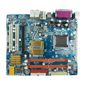
Page 9: Configuration
Mainboard PM945GC(V2.0) Configuration Layout of PM945GC (V2.0) -
Page 10: Hardware Installation
CPU Processor Installation ® This mainboard supports Intel Core using a Socket 775. Before building your system, we suggest you to visit the Intel website and review the processor installation procedures. http://www.intel.com CPU Socket 775 Configuration Steps: Locate the CPU socket 775 on your mainboard and nudge the lever away from the socket as shown. -
Page 11: Memory Installation: Dimm1/Dimm2
Memory Installation: DIMM1/DIMM2 The PM945GC(V2.0) provides two DIMM (Dual In-Line Memory Modules) sockets which allowing you to install 240-pin, unbuffered non-ECC, DDRII 667 (by overclocking)/ DDRII 533 SDRAMs. It also supports Dual Channel Technology and allows you installing a total memory capacity of 4 GB. -
Page 12: Memory Installation Steps
For enabling Dual-Channel, you have to install two memories in the DIMM sockets at the same time; according to the definition by Intel, once one channel of the memory capacity is the same with the other channel, then Dual-Channel will be enabled. -
Page 13: Back Panel Configuration
There are four onboard USB 2.0/ 1.1 ports on the back panel. These USB ports are used to attach with USB devices, such as keyboard, mice and other USB supported devices. There is also a 10/100 Mbps Ethernet LAN port available for you to attach an Internet cable. Mainboard PM945GC(V2.0) -
Page 14: Front Panel Headers: Jw_Fp, Pwrled, Speak
2-channel to 6-channel audio. See Appendix I for more information. Front Panel Headers: JW_FP, PWRLED, SPEAK Assignment VCC5 (+) Hard Drive LED (HDLED) HDDLE (-) Reset Switch RSTSW (RESET) Mainboard PM945GC(V2.0) JW_FP Function Assignment VCC5 (+) PWRLED (-) PWRBTN Function 2-pin Power LED (PWR LED) -
Page 15: Connectors
Connectors Floppy Disk Drive Connector: FLOPPY These mainboards provide a standard floppy disk drive connector (FDD) that supports 360KB/ 720KB/ 1.2MB/ 1.44MB/ 2.88 MB floppy disk drives using a FDD ribbon cable. Mainboard PM945GC(V2.0) Assignment Assignment PWR_LED (+) PWR_LED (-) -
Page 16: Headers & Jumpers
If you are using a USB 2.0 device with Windows 2000/XP, you will need to install the USB 2.0 driver from the Microsoft Service pack 2 (or later) for Windows later) for Windows® 2000, you will not have to install the driver. Mainboard PM945GC(V2.0) Assignment Assignment -DATA... - Page 17 USB port that the USB device is attached to. Assignment Pin 1-2 Closed Pin 2-3 Closed Note: Close stands for putting a jumper cap onto two header pins. Mainboard PM945GC(V2.0) Assignment KB/MS & USB Power ON Disable (Default) KB/MS & USB Power ON Enabled Assignment...
-
Page 18: Audio Configuration
The SPDIF output is capable of providing digital audio to external speakers or compressed AC3 data to an external Dolby digital decoder. Use the feature only when your stereo system has digital input function. Assignment HDMI_SPDIF_OUT Mainboard PM945GC(V2.0) Assignment Normal (Default) Clear CMOS Data... -
Page 19: Slots
PE2 slot which the interface is capable for PCI-E x16 specification. PCI Interface Slots: PCI1/2 PCI stands for Peripheral Component Interconnect, which is a bus standard for installing expansion cards such as network card, SCSI card, etc. to these PCI slots. Mainboard PM945GC(V2.0) AUDIO Assignment AUD_GND AUD_JD... -
Page 20: Power Supply Attachments
Attention In general, power cords are designed and should be attached with a specific direction. The black wire of the power cord is Ground and should be attached onto the header location of Ground. Mainboard PM945GC(V2.0) Assignment +3.3V +3.3V Ground... -
Page 21: Chapter 2. Bios Setup
The PHOENIX-AWARD BIOS installed in your computer system’s ROM is a custom version of an industry standard BIOS. This means that it supports the BIOS of Intel This version of the PHOENIX-AWARD protection as well as special configurations for fine-tuning the system chipset. The defaults for the BIOS values contained in this document may vary slightly with the version installed in your system. -
Page 22: Main Menu
Include all the adjustable items of chipset special features. Integrated Peripherals Include all onboard peripherals. Power Management Setup Include all the adjustable items of Green function features. PnP/PCI Configurations Include all configurations of PCI and PnP ISA resources. Mainboard PM945GC(V2.0) -
Page 23: Load Optimized Defaults
Set change or disable password. It allows you to limit access to the system. Save & Exit Setup Save CMOS value settings to CMOS and exit setup. Exit Without Saving Abandon all CMOS value changes and exit setup. Mainboard PM945GC(V2.0) -
Page 24: Chapter 3: Software Setup
Place the Driver CD into the CD-ROM drive and the Installation Utility will auto-run. You can also launch the Driver CD Installation Utility manually by executing the Intel.exe program located on the Driver CD. (For more details, please refer to the Readme.txt files that in each folder of the Driver.) ◎... - Page 25 For Windows Vista Driver For Windows XP (64bit) Driver Attention Before you install the Realtek Audio Driver on Windows operating system, please go to the Microsoft update for enabling HD Audio. Mainboard PM945GC(V2.0) ® XP (64bit) ® website to install the...
- Page 26 Mainboard PM945GC(V2.0) For Windows XP (32bit) Driver For Windows 2000 Driver...
- Page 27 Intel Chipset INF – It provides all drivers for the functions which built in both the Northbridge/ Southbridge. Intel VGA Driver – It provides the driver of Intel VGA. Marvell LAN Driver – It provides the driver of Marvell Network.
-
Page 28: Chapter 4: Troubleshooting
Problem 4: System only boots from the CD-ROM. The hard disk can be read and applications can be used but booting from the hard disk is impossible. Causes: Hard Disk boot sector has been corrupted. Mainboard PM945GC(V2.0) - Page 29 2. Use anti-virus programs to detect and clean viruses. Problem 9: Screen goes blank periodically. Causes: Screen saver is enabled. Solutions: Disable screen saver. Problem 10: Keyboard failure. Causes: Keyboard is disconnected. Solutions: Reconnect keyboard. Replace keyboard if you continue to experience problems. Mainboard PM945GC(V2.0)
- Page 30 Problem 14: Missing operating system on hard drive. Causes: CMOS setup has been changed. Solutions: Run setup and select the correct drive type. Problem 15: Certain keys do not function. Causes: Keys jammed or defective. Solutions: Replace keyboard. Mainboard PM945GC(V2.0)
-
Page 31: Channels Setup
Click “Audio I/O” button, you can see the screen like the picture below. You can choose 2, 4, 6 or 8 channels by your speakers. You can click the “Auto test” button Mainboard PM945GC(V2.0) from the Windows screen. to test your audio devices.
Need help?
Do you have a question about the PM945GC and is the answer not in the manual?
Questions and answers