Table of Contents
Advertisement
Quick Links
Download this manual
See also:
User Manual
Advertisement
Table of Contents

Related Manuals for Kramer VP-8x8TP


Summary of Contents for Kramer VP-8x8TP
- Page 1 Kramer Electronics, Ltd. USER MANUAL Model: VP-8x8TP 8x8 UXGA/Audio Matrix Switcher...
-
Page 2: Table Of Contents
Defining the VP-8x8TP 8x8 UXGA/Audio Matrix Switcher Installing the VP-8x8TP in a Rack Connecting and Configuring the VP-8x8TP 8x8 UXGA/Audio Matrix Switcher 10 Connecting the VP-8x8TP 8x8 UXGA/Audio Matrix Switcher Connecting to the VP-8x8TP 8x8 UXGA/Audio Matrix Switcher via RS-485 6.2.1... - Page 3 Using the IR Transmitter Operating Multiple VP-8x8TP Units Remotely via RS-232 Operating the VP-8x8TP Remotely via your Web Browser Connecting to the VP-8x8TP 8x8 UXGA/Audio Matrix Switcher via your Browser 25 The Main Switching Matrix Page 9.2.1 Switching an Input to an Output 9.2.2...
- Page 4 Tables Table 1: Terminology Used in this Manual Table 2: VP-8x8TP Front and Rear Panel Features Table 3: Technical Specifications of the VP-8x8TP 8x8 UXGA/Audio Matrix Switcher 34 Table 4: Default Communication Parameters Table 5: VP-8x8TP Video Signal Codes Table 6: VP-8x8TP Audio Signal Codes...
-
Page 5: Introduction
Introduction Introduction Welcome to Kramer Electronics! Since 1981, Kramer Electronics has been providing a world of unique, creative, and affordable solutions to the vast range of problems that confront the video, audio, presentation, and broadcasting professional on a daily basis. In recent years, we have redesigned and upgraded... - Page 6 Getting Started KRAMER: SIMPLE CREATIVE TECHNOLOGY...
-
Page 7: Overview
(optional) • A Web browser over Ethernet The VP-8x8TP is dependable, rugged, and fits into one vertical space (1U) of a standard 19” professional rack. 1 For example, C-GM/5BM The complete list of Kramer cables is available at... -
Page 8: Terminology Used In This User Manual
STP cable available, and we advise you to use the best quality STP cable that you can afford. Our non-skew-free cable, Kramer BC-STP is intended for digital signals and for analog signals where skewing is not an issue. -
Page 9: Defining The Edid
Overview Defining the EDID The Extended Display Identification Data (EDID ) is a data-structure, provided by a display, to describe its capabilities to a graphics card (that is connected to the display’s source). The EDID enables the PC or laptop to “know” what kind of monitor is connected to the output. -
Page 10: Defining The Vp-8X8Tp 8X8 Uxga/Audio Matrix Switcher
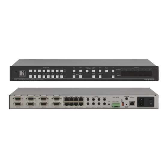
Defining the VP-8x8TP 8x8 UXGA/Audio Matrix Switcher Defining the VP-8x8TP 8x8 UXGA/Audio Matrix Switcher Figure 1 Table 2 define the front panel of the VP-8x8TP 8x8 UXGA/Audio Matrix Switcher. Figure 1: VP-8x8TP 8x8 UXGA/Audio Matrix Switcher Front Panel Figure 2 Table 2 define the rear panel of the VP-8x8TP 8x8 UXGA/Audio Matrix Switcher. -
Page 11: Table 2: Vp-8X8Tp Front And Rear Panel Features
Defining the VP-8x8TP 8x8 UXGA/Audio Matrix Switcher Table 2: VP-8x8TP Front and Rear Panel Features Feature Function IR Receiver Receiver for the infrared remote control transmitter IR LED LED lights yellow when the unit receives IR commands SELECTOR OUT Buttons... - Page 12 AC mains power fuse 25 Power Switch Turns the AC mains power ON/OFF 26 PROG Button Push in for “Program” to upgrade to the latest Kramer firmware via RS-232 (see Section 8), or release for “Normal” operation ( he factory default)
-
Page 13: Installing The Vp-8X8Tp In A Rack
Installing the VP-8x8TP in a Rack Installing the VP-8x8TP in a Rack This section describes what to do before installing in a rack and how to rack mount the VP-8x8TP. -
Page 14: Connecting And Configuring The Vp-8X8Tp 8X8 Uxga/Audio Matrix Switcher
Connecting and Configuring the VP-8x8TP 8x8 UXGA/Audio Matrix Switcher This section includes: • Connecting the VP-8x8TP 8x8 UXGA/Audio Matrix Switcher (see Section 6.1) • Connecting to the VP-8x8TP 8x8 UXGA/Audio Matrix Switcher via RS-485 (see Section 6.2) • Configuring the Ethernet Port (see Section 6.4) -
Page 15: Connecting To The Vp-8X8Tp 8X8 Uxga/Audio Matrix Switcher Via Rs-485
1 You do not need to connect all inputs and outputs 2 Switch OFF the power on each device before connecting it to your VP-8x8TP After connecting your VP-8x8TP, switch on its power and then switch on the power on each device DO NOT push in the rear panel Flash Program “PROG” button, it is used only for... -
Page 16: Setting The Rs-485 Bus Termination
4) ON (for RS-485 Line Termination with 120Ω) if there is only one VP-8x8TP on the RS-485 bus. If there are multiple VP-8x8TP units on the RS-485 bus, only the first and last units on the RS-485 bus termination should be set to ON. -
Page 17: Figure 5: Local Area Connection Properties Window
Connecting and Configuring the VP-8x8TP 8x8 UXGA/Audio Matrix Switcher 6.4.1.1 Connecting the Ethernet Port Directly to a PC You can connect the Ethernet port of the machine to the Ethernet port on your PC, via a crossover cable with RJ-45 connectors. -
Page 18: Ethernet Port Configuration
6.4.1.2 Connecting the ETHERNET Port via a Network Hub, Switch, or Router You can connect to the Ethernet port of the VP-8x8TP to the Ethernet port on a network hub, switch, or router, via a straight-through cable with RJ-45 connectors. -
Page 19: Figure 7: Connect Window
Connecting and Configuring the VP-8x8TP 8x8 UXGA/Audio Matrix Switcher Figure 7: Connect Window 3. Select one of the following methods to connect to the Ethernet port of the VP-8x8TP: Ethernet, if you are connected via an Ethernet cable. Enter the IP address or the machine name The default IP address is 192.168.1.39 and the default name for the unit is... -
Page 20: Operating The Vp-8X8Tp 8X8 Uxga/Audio Matrix Switcher Remotely
6. Click Set to save changes, or click Close to exit without saving the changes. Operating the VP-8x8TP 8x8 UXGA/Audio Matrix Switcher Remotely You can operate the VP-8x8TP remotely via RS-232, RS-485, and/or Ethernet using the Kramer K-Router application. If you are operating a standalone unit via RS-232 or the Ethernet, configure the... -
Page 21: Operating The Vp-8X8Tp 8X8 Uxga/Audio Matrix Switcher
2. Press an INPUT button to select the input to switch to the output. The selected input number appears on the 7-segment display. Incomplete operations on the VP-8x8TP timeout after 15 seconds 7.1.2 Switching an Input to all Outputs To switch an input to all outputs: 1. -
Page 22: Disconnecting All Inputs From Outputs
Operating the VP-8x8TP 8x8 UXGA/Audio Matrix Switcher 7.1.4 Disconnecting all Inputs from Outputs To disconnect all inputs from outputs: 1. Press the ALL button. The 7-segment display flashes. 2. Press the OFF button. All inputs are disconnected from the outputs and display 0 on the 7-segment display. -
Page 23: Status Display During Audio Level Setting
Operating the VP-8x8TP 8x8 UXGA/Audio Matrix Switcher (see Section 7.6.1), the display is for both signal configurations 7.2.3 Status Display During Audio Level Setting During audio gain level setting, the Status display indicates: • Which channel number is selected (in this example, 3) •... -
Page 24: Confirming A Switching Action
Operating the VP-8x8TP 8x8 UXGA/Audio Matrix Switcher 2. Press the lit TAKE button to toggle from the Confirm mode back to the At Once mode. Actions no longer require user confirmation and the TAKE button no longer lights. 7.3.2 Confirming a Switching Action To confirm a switching configuration change (in the Confirm mode): 1. -
Page 25: Recalling An Input-Output Configuration
• Breakaway, in which video and audio channels switch independently 1 By pressing the RCL button followed by the INPUT/OUTPUT buttons 2 Even when the front panel is locked you can still operate via RS-232 or RS-485, as well as via the Kramer RC-IR3 infrared remote control transmitter... -
Page 26: Setting The Audio-Follow-Video Option
Operating the VP-8x8TP 8x8 UXGA/Audio Matrix Switcher 7.6.1 Setting the Audio-Follow-Video Option To set the Audio-follow-video (AFV) option, press the AFV button. One of the following occurs: • If the AUDIO and VIDEO configurations are the same, then the AFV button lights. -
Page 27: Using The Ir Transmitter
1. Connect the sources and acceptors to the VP-8x8TP (see Section 6.1). 2. Connect the RS-232 port of the first VP-8x8TP unit to the PC or serial controller. 3. Connect the RS-485 port on the first VP-8x8TP to the RS-485 port on the... -
Page 28: Operating The Vp-8X8Tp Remotely Via Your Web Browser
Operating the VP-8x8TP Remotely via your Web Browser Figure 14: Control Configuration via RS-232 and RS-485 Operating the VP-8x8TP Remotely via your Web Browser You can remotely operate the VP-8x8TP using a Web browser via the Ethernet connection (see Section 9.1). -
Page 29: Connecting To The Vp-8X8Tp 8X8 Uxga/Audio Matrix Switcher Via Your Browser
Operating the VP-8x8TP Remotely via your Web Browser Connecting to the VP-8x8TP 8x8 UXGA/Audio Matrix Switcher via your Browser Make sure that your PC is connected via a network to the VP-8x8TP and do the following: 1. Open your Internet browser. -
Page 30: The Main Switching Matrix Page
Operating the VP-8x8TP Remotely via your Web Browser Figure 18: First Time Security Warning 3. Click Run. The main switching control page is displayed which shows a graphical representation of the front panel (see Figure 19). There are three remote operation Web pages: •... -
Page 31: Switching An Input To An Output
Operating the VP-8x8TP Remotely via your Web Browser The main switching matrix page allows you to: • Switch any audio/video input to any/all outputs independently (see Section 9.2.1) • Set the audio to operate in AFV (Audio Follow Video) mode (see Section 9.2.2) -
Page 32: Operating In The Offline Mode
Operating the VP-8x8TP Remotely via your Web Browser 1. Click the AFV button. The following warning appears. Figure 22: AFV Mode Warning 2. Click OK. The AFV button outline becomes dark. All audio channels are switched according to the corresponding video channels. -
Page 33: Storing And Recalling Setups
Operating the VP-8x8TP Remotely via your Web Browser Figure 24: Switching Audio in the Offline Mode 3. If required, repeat Step 2 for several audio/video channels. 4. Click either Take to accept the change or Cancel. 5. Click the Online button to exit the Offline mode. - Page 34 Operating the VP-8x8TP Remotely via your Web Browser Figure 26: Selecting Preset 07 2. Click Store. A confirmation message appears. 3. Click OK. The configuration is stored in Preset 07. To recall a setup: 1. From the Preset drop-down list, select a preset (in this example, Preset 03).
-
Page 35: Locking The Front Panel Buttons
Operating the VP-8x8TP Remotely via your Web Browser 2. Click Recall. A confirmation message appears. 3. Click OK. The configuration from Preset 03 is loaded. Note: You can also recall a preset in the Offline mode (see Figure 29) and make it... -
Page 36: The Configuration Page
Operating the VP-8x8TP Remotely via your Web Browser Figure 30: Selecting Audio Input Gain for Channel 2 2. Click the – or + button to decrease or increase the gain. Hold the – or + button down to cycle through the values. -
Page 37: Edid
14). The EDID for each input can be changed independently by uploading an EDID binary file to each input via the RS-232 port using Kramer EDID Sender software Firmware Upgrade For instructions on upgrading the firmware, see the Updating the Firmware Using the P3K Software document. -
Page 38: Technical Specifications
ACCESSORIES: Power cord, Windows -based control software, external remote IR receiver cable Default Communication Parameters Table 4 lists the default communication parameters as used in the VP-8x8TP. Table 4: Default Communication Parameters RS-232 Protocol 2000 Protocol 3000 (Default) Baud Rate:... -
Page 39: Default Edid
Gateway: 192.168.1.1 TCP Port #: 5000 UDP Port #: 50000 Default EDID The default EDID is stored in all inputs. Monitor Model name VP-8X8TP Manufacturer Plug and Play, ID KRM0808 Serial number Manufacture date 2009, ISO week 10 ED D revision Input signal type Analog 0.700, 0 000 (0.7 Vp-p) -
Page 40: Table 5: Vp-8X8Tp Video Signal Codes
36,00,30,E4,10,00,00,18,BC,1B,00,A0,50,20,17,30,30,20,36,00,20,20,00,00,00,1A,00,00,00,FC,00,56, 50,2D,38,58,38,54,50,0A,20,20,20,20,00,00,00,10,00,56,50,2D,38,58,38,54,50,20,0A,20,20,20,00,4A Table 5 Table 6 list the ASCII codes that switch an input to an output for a single VP-8x8TP machine. Table 5: VP-8x8TP Video Signal Codes OUT 1 OUT 2 OUT 3 OUT 4 OUT 5 OUT 6... -
Page 41: Tables Of Hex Codes For Serial Communication (Protocol 2000)
The hex codes listed in this section are used to set video channels for a single machine (set as Machine 1) connected via either RS-232 or Ethernet. Similar hex codes are used when the VP-8x8TP is connected via RS-485 and the machine is set to number 2. -
Page 42: Kramer Protocol
Protocol 3000 and Protocol 2000. Section 16.2 defines Protocol 3000 and Section 16.3 defines Protocol 2000. By default, the VP-8x8TP is set to Kramer’s Protocol 3000, but it is also compatible with Protocol 2000. 16.1 S witching Protocols 3 8 B... -
Page 43: Switching Protocols Via Protocol Commands
• 0x38, 0x80, 0x83, 0x81 The Windows®-based Kramer control software operates with Protocol 2000. If the VP-8x8TP is set to Protocol 3000, it is automatically switched to Protocol 2000. 16.2 Kramer Protocol 3000 This RS-232/RS-485 communication protocol lets you control the machine from ®... -
Page 44: Command Parts Details
2000, in Protocol 2000 there is already such a command to switch Protocol to ASCII Protocol (#56 : H38 H80 H83 H81) Table 12: Instruction Codes for Protocol 3000 Help commands Command Syntax Response Protocol Handshaking ~OKCRLF Device initiated messages Command Syntax Start message Kramer Electronics LTD. , Device Model Version Software Version KRAMER: SIMPLE CREATIVE TECHNOLOGY... - Page 45 Kramer Protocol Switcher actions Audio-video channel has switched (AFV mode) AV IN>OUT Video channel has switched (Breakaway mode) VID IN>OUT Audio channel has switched (Breakaway mode) AUD IN>OUT Result codes (errors) Syntax No error. Command running succeeded COMMAND PARAMETERS OK...
- Page 46 PRST-AUD? PRESET, * PRST-AUD PRESET: IN>1, IN>2,… Read saved presets list PRST-LST? PRST-LST PRESET, PRESET, … Short form: PLST? Parameters Description: PRESET = Preset number. OUT = Output in preset to show for, '*' for all. KRAMER: SIMPLE CREATIVE TECHNOLOGY...
- Page 47 Numeric value (present audio processing stage). For example: "0" for Input level, "1" for Pre-Amplifier, "2" for Amplifier (Out) etc. CHANNEL = Input or Output # VOLUME = Audio parameter in Kramer units, precede minus sign for nega ive values. increase current value, decrease current value.
- Page 48 NET-IP IP_ADDRESS NET-IP IP_ADDRESS RESULT NTIP Read IP Address NET-IP? NET-IP IP_ADDRESS NTIP? Read MAC Address NET-MAC? NET-MAC MAC_ADDRESS NTMC Set subnet mask NET-MASK SUBNET_MASK NET-MASK SUBNET_MASK RESULT NTMSK Read subnet mask NET-MASK? NET-MASK SUBNET_MASK NTMSK? KRAMER: SIMPLE CREATIVE TECHNOLOGY...
- Page 49 Kramer Protocol Network settings commands Set gateway address NET-GATE GATEWAY_ADDRESS NET-GATE GATEWAY_ADDRESS RESULT NTGT Read subnet mask NET-GATE? NET-GATE GATEWAY_ADDRESS NTGT? Set DHCP mode NET-DHCP DHCP_MODE NET-DHCP DHCP_MODE RESULT NTDH NET-DHCP? Read subnet mask NET-DHCP DHCP_MODE NTDH? DHCP_MODE = 0 – Don't use DHCP (Use IP set by factory or IP set command).
-
Page 50: Kramer Protocol 2000
Kramer Protocol 16.3 Kramer Protocol 2000 This RS-232/RS-485 communication protocol uses four bytes of information as defined below. The default data rate is 9600 baud, with no parity, 8 data bits and 1 stop bit. Table 13: Protocol Definitions DESTI-... -
Page 51: Table 14: Instruction Codes For Protocol 2000
Kramer Protocol Table 14: Instruction Codes for Protocol 2000 Note: All values in the table are decimal, unless otherwise stated INSTRUCTION DEFINITION FOR SPECIFIC INSTRUCTION NOTE DESCRIPTION INPUT OUTPUT RESET VIDEO SWITCH V DEO Set equal to video input Set equal to video output which is... - Page 52 This code is also returned to the PC if an RS-232 instruction is sent while the machine is being programmed via the front panel Reception of this code by the switcher is not valid NOTE 10 – This code is reserved for internal use KRAMER: SIMPLE CREATIVE TECHNOLOGY...
- Page 53 Kramer Protocol NOTE 13 - This is a request to identify the switcher/s in the system If the OUTPUT is set as 0, and the INPUT is set as 1, 2, 5 or 7, the machine will send its name The reply is the decimal value of the INPUT and OUTPUT For example, for a 2216, the reply to the request...
- Page 54 EXCLUSION OF DAMAGES The liability of Kramer for any effective products is limited to the repair or replacement of the product at our option Kramer shall not be liable for: Damage to other property caused by defects in this product, damages based upon inconvenience, loss of use of the product, loss of time, commercial loss;...
- Page 55 For the latest information on our products and a list of Kramer distributors, visit our Web site www.kramerelectronics.com where updates to this user manual may be found. We welcome your questions, comments and feedback. Safety Warning: Disconnect the unit from the power supply before opening/servicing.
Need help?
Do you have a question about the VP-8x8TP and is the answer not in the manual?
Questions and answers