Omron RX User Manual
200 v class three-phase input 0.4 to 55 kw; 400 v class three-phase input 0.4 to 132 kw
Hide thumbs
Also See for RX:
- User manual (688 pages) ,
- System configuration manual (19 pages) ,
- User manual (82 pages)

Subscribe to Our Youtube Channel
Related Manuals for Omron RX


Summary of Contents for Omron RX
- Page 1 Cat. No. I560-E2-03-X Customised to your machine Model: RX 200 V Class Three-Phase Input 0.4 to 55 kW 400 V Class Three-Phase Input 0.4 to 132 kW USER’S MANUAL...
- Page 3 After reading this manual, keep it handy for future reference. This manual describes the specifications and functions of the product as well as the relations between them. You should assume that anything not described in this manual is not possible with the product.
- Page 4 PRODUCTS, WHETHER SUCH CLAIM IS BASED ON CONTRACT, WARRANTY, NEGLIGENCE, OR STRICT LIABILITY. In no event shall the responsibility of OMRON for any act exceed the individual price of the product on which liability is asserted. IN NO EVENT SHALL OMRON BE RESPONSIBLE FOR WARRANTY, REPAIR, OR OTHER CLAIMS...
- Page 5 The following are some examples of applications for which particular attention must be given. This is not intended to be an exhaustive list of all possible uses of the products, nor is it intended to imply that the uses listed may be suitable for the products: •...
-
Page 6: Dimensions And Weights
PERFORMANCE DATA Performance data given in this manual is provided as a guide for the user in determining suitability and does not constitute a warranty. It may represent the result of OMRON's test conditions, and the users must correlate it to actual application requirements. -
Page 7: Safety Precautions
Doing so may result in a serious injury due to an electric shock. Be sure to ground the unit. Not doing so may result in a serious injury due to an electric shock or fire. - Page 8 Do not connect resistors to the terminals (PD/+1, P/+, N/-) directly. Doing so might result in a small- scale fire, heat generation or damage to the unit. Install a stop motion device to ensure safety. Not doing so might result in a minor injury. (A holding brake is not a stop motion device designed to ensure safety.) Be sure to use a specified type of braking resistor/regenerative braking unit.
-
Page 9: Precautions For Safe Use
Transporting, Installation, and Wiring •Do not drop or apply strong impact on the product. Doing so may result in damaged parts or malfunction. •Do not hold by the front cover and terminal block cover, but hold by the fins during transportation. -
Page 10: Precautions For Correct Use
•Confirm that the rated input voltage of the Inverter is the same as AC power supply voltage. Error Retry Function •Do not come close to the machine when using the error retry function because the machine may abruptly start when stopped by an alarm. - Page 11 Precautions for Correct Use Warning Labels Warning labels are located on the Inverter as shown in the following illustration. Be sure to follow the instructions. Warning Description...
-
Page 12: Checking Before Unpacking
Checking Before Unpacking Checking the Product On delivery, be sure to check that the delivered product is the Inverter RX model that you ordered. Should you find any problems with the product, immediately contact your nearest local sales representative or OMRON sales office. -
Page 13: Revision History
Revision History Revision History A manual revision code appears as a suffix to the catalog number located at the lower left of the front and back covers. I560-E2-03 Cat. No. Revision code Revision code Revision date Changes and revision pages... -
Page 15: About This Manual
About This Manual About This Manual This User's Manual is compiled chapter by chapter for user's convenience as follows. Understanding the following configuration ensures more effective use of the product. Overview Chapter 1 Overview Describes features and names of parts. -
Page 17: Table Of Contents
Chapter 2 Design Installation....................2-1 Wiring.......................2-6 Chapter 3 Operation Operation Method ..................3-3 Test Run Procedure.................3-4 Test Run Operation .................3-5 Part Names and Descriptions of the Digital Operator......3-8 Keys......................3-11 Parameter Transition ................3-12 Parameter List ..................3-18 Chapter 4 Functions Monitor Mode...................4-1 Function Mode ..................4-8 Functions When PG Option Board (3G3AX-PG01) Is Used....4-119... - Page 18 Contents Chapter App Appendix Appendix-1Parameter List ................. App-1 Appendix-2Product Life Curve ................App-38 Appendix-3Life Alarm Output................App-39 Index...
-
Page 19: Chapter 1 Overview
Chapter 1 Overview 1-1 Functions ............1-1 1-2 Appearance and Names of Parts ....1-4... -
Page 20: Functions
1-1 Functions 1Overview 1-1 Functions RX Inverter Models Rated voltage Enclosure rating Max. applicable motor capacity Model 0.4 kW RX-A2004 0.75 kW RX-A2007 1.5 kW RX-A2015 2.2 kW RX-A2022 3.7 kW RX-A2037 5.5 kW RX-A2055 7.5 kW RX-A2075 3-phase 200 V AC... - Page 21 The RX Series provides sensor-less vector control, which is useful for up/down applications. It can provide a high torque of 150%, even at a speed reference of 0 Hz (150% torque is available when the Inverter capacity is increased by one rank). This function contributes to simplification of control programs and extension of the service life of the brake.
- Page 22 Transport of Japan The RX Series incorporates a zero-phase reactor (radio noise filter) as a standard specification. When an optional DC reactor is added, the RX Series meets the requirements specified by the Min- istry of Land, Infrastructure and Transport of Japan.
-
Page 23: Appearance And Names Of Parts
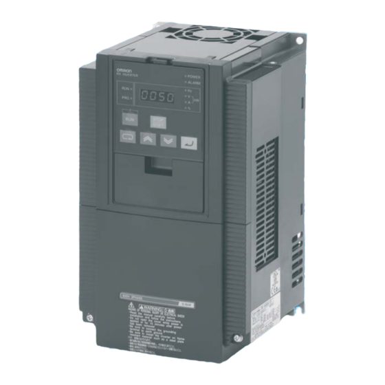
Spacer cover Terminal block cover Open the terminal block cover and you can connect cables to the main circuit terminal block, as well as the control circuit terminal block. Also, open the front cover and you can mount the optional board. -
Page 25: Chapter 2 Design
Chapter 2 Design 2-1 Installation ............2-1 2-2 Wiring ..............2-6... -
Page 26: Installation
Doing so may result in a serious injury due to an electric shock. Be sure to ground the unit. Not doing so may result in a serious injury due to an electric shock or fire. (200-V class: type-D grounding, 400-V class: type-C grounding) CAUTION Do not connect resistors to the terminals (PD/+1, P/+, N/-) directly. -
Page 27: Safety Information
Transporting, Installation, and Wiring •Do not drop or apply strong impact on the product. Doing so may result in damaged parts or malfunction. •Do not hold by the front cover and terminal block cover, but hold by the fins during transportation. - Page 28 •Increased ambient temperatures will shorten the life of the Inverter. •Keep the Inverter away from heating elements (such as a braking resistor, DC reactor, etc.). If the Inverter is installed in an enclosure, keep the ambient temperature within the range of the specifications, taking dimensions and ventilation into consideration.
- Page 29 2-1 Installation •To raise the carrier frequency, reduce the output current (or derate the rated current) as shown in the graph below. Voltage 200-V class 400-V class Capacity Max. fc (kHz) Derating at fc = 15 kHz Max. fc (kHz) Derating at fc = 15 kHz 0.4 kW...
- Page 30 Unnecessary portion Inverter with 30 kW or Higher Capacity For Connection Without Cable Conduit Make a cut in the rubber bushing of the backing plate with nippers or a wire cutter, and insert a ca- ble. Backing plate Rubber bushing For Connection With Cable Conduit Remove the rubber bushing from the conduit connecting portions, and connect the cable conduit.
-
Page 31: Wiring
S/L2 T/L3 W/T3 3-phase 200 V AC 3-phase 400 V AC Short-circuit wire To wire the control circuit power supply and main circuit power supply separately, be sure to Relay output *1 remove the J51 connector Control circuit wire first. -
Page 32: Main Circuit Terminals
DC reactor. P/+, RB Braking resistor Connect optional external braking resistors. (The RB connection terminals terminal is provided for the Inverters with 22 kW or lower capacity.) P/+, N/- Regenerative braking Connect optional regenerative braking units. unit connection terminal Ground terminal Inverter case ground terminal. - Page 33 Multi-function analog This terminal outputs a signal selected from Allowable max. current: output the "0 to 10 V DC Voltage Output" monitor 2 mA (Voltage) items: Output frequency, Output current, Output torque (with/without sign), Output voltage, Input power, Electronic thermal load rate, LAD frequency, Motor temperature, and Fin temperature.
- Page 34 Input impedance and allocate them to terminals 1 to 8. between each input terminal and the CM1 Note: Only terminals 1 and 3 can be used for the terminal: 4.7 kΩ emergency shutoff function. For details, refer to "Emergency Shutoff Function"...
- Page 35 Inverter activates an emergency shutoff trip [E37. *]. After checking the cable connection and the signal logic, input the reset signal (RS). Emergency shutoff trip [ E37. * ] can be reset only by the reset signal (RS) via multi-function input terminal 1. (It cannot be reset with the Digital Operator.) •To enable this function, set the slide switch SW1 lever in the Inverter to [ON].
- Page 36 *2. When [C003] is [64 (EMR)], [C013] is fixed to [01 (NC)]. *3. If [18 (RS)] has been allocated to a multi-function input terminal (except for 3) other than terminal 1 before switch SW1 is set to "ON", the input terminal selection for the relevant terminal will be automatically changed to "no (no allocation)"...
- Page 37 2-2 Wiring *5. Once slide switch SW1 is set to [ON], allocation of multi-function input terminals 1 and 3 will not be restored, even if SW1 is reset to [OFF] afterward. Re-allocate the terminal function. Slide switch SW1 Slide lever (factory default: OFF)
- Page 38 • To connect several motors, provide a thermal relay for each. • The RC value of each thermal relay should be 1.1 times of the motor rated current. The relay may trip easily depending on the cable length. In this case, connect an AC reactor to the Inverter output.
- Page 39 (conventional special type 3 grounding: ground resistance 10 Ω or less). • For the ground cable, use the applicable cable or a cable with a larger diameter. Make the cable length as short as possible.
- Page 40 2-2 Wiring Arrangement of Main Circuit Terminals The terminal arrangement on the Inverter main circuit terminal block is shown below. Terminal arrangement Applicable model R/L1 S/L2 T/L3 U/T1 V/T2 W/T3 PD/+1 CHARGE LED indicator When not using the DC reactor,...
- Page 41 Ground terminal: M6 Others: M6 PD/+1 - P/+ short-circuit bar When not using the DC Ground terminal with short-circuit reactor, keep the PD/+1 - P/+ bar (shaded area) for EMC filter short-circuit bar attached. function switching [EMC filter function switching method]...
- Page 42 RX-A2550 (shaded area) for EMC When not using the DC filter function switching reactor, keep the PD/+1 - P/+ short-circuit bar attached. Ro,To: M4 [EMC filter function switching method] Ground terminal: M8 Others: M10 EMC filter enabled (factory default)
- Page 43 2-2 Wiring Recommended Cable Size, Wiring Device and Crimp Terminal For Inverter wiring, crimp terminal and terminal screw tightening torque, refer to the table below. Power cable Applicable External Motor Applicable Ground Terminal Tightening device braking resistor Crimp output Inverter...
- Page 44 350 A B413K (35.0 max.) *1. When the cable is connected without using the crimp terminal (bare wires), use the square washer included with the product. Note: The cable size is based on the HIV cable (75°C heat resistance). 2-19...
- Page 45 Connection for Separating Inverter Control Circuit Power Supply from Main Power Supply If the Inverter protection circuit is activated to turn off the magnetic contactor of the Inverter input power supply, the power to the Inverter control circuit is also turned off, and the alarm signal cannot be kept on.
- Page 46 2-2 Wiring Wiring Control Circuit Terminals • Terminals L and PLC are insulated from each other via the input and output signal common terminals. Do not short-circuit or ground these common terminals. Do not ground these common terminals via external equipment. (Check the external equipment ground conditions.)
- Page 47 2-2 Wiring Selecting the Sequence Input Method (Sink/Source Logic) When external power supply is used When the Inverter's internal interface power supply is (Remove the short-circuit bar from the control used terminal block.) Short-circuit 24 V DC 24 V DC DC24V Output unit etc.
- Page 48 • To use the Digital Operator apart from the Inverter body, place an order for the optional cable 3G3AX-CAJOP300-EE (3 m). • The optional cable should be 3 m or less. Using a cable longer than 3 m may cause malfunction. Conforming to EC Directives Conforming Standards •EMC directive...
- Page 49 Operation 3-1 Operation Method ..........3-3 3-2 Test Run Procedure ......... 3-4 3-3 Test Run Operation.......... 3-5 3-4 Part Names and Descriptions of the Digital Operator ............3-8 3-5 Keys..............3-11 3-6 Parameter Transition ........3-12 3-7 Parameter List ..........3-18...
- Page 50 Doing so may result in a serious injury due to an electric shock. Do not operate the Digital Operator or switches with wet hands. Doing so may result in a serious injury due to an electric shock. Inspection of the Inverter must be conducted after the power supply has been turned off. Not doing so may result in a serious injury due to an electric shock.
- Page 51 •When checking a signal with the main power supply applied, if a signal voltage is erroneously applied to the control input terminals, the motor may start abruptly. Be sure to confirm safety before checking a signal.
-
Page 52: Operation Method
Terminal" (page 2-7). (Requirements for operation) • RUN command: Switch, Relay etc. • Frequency reference: External signal (e.g. 0 to 10 V DC, -10 to 10 V DC, 4 to 20 mA) Control circuit terminal block RUN command (switch) Frequency reference... -
Page 53: Test Run Procedure
• Data display : Displays the set value in d001. • If an error occurs, the error code is displayed on the data display. In this case, refer to "Chapter 5 Maintenance Operations" and make the necessary changes to remedy. -
Page 54: Test Run Operation
•Make sure that the motor output terminals (U/T1, V/T2, and W/T3) are connected to the motor correctly. •Make sure that the control circuit terminals and the control device are wired correctly and that all control terminals are turned off. •Set the motor to no-load status (i.e., not connected to the mechanical system). - Page 55 Press the Mode key. The set value in "b084" is displayed. Use the Increment or Decrement key to display "02". bk0k8k4 Press the Enter key. The set value is entered and "b084" is displayed. Press the STOP/RESET key while holding down the Mode and Decrement keys simultaneously.
- Page 56 Connecting the Mechanical System •After confirming that the motor has stopped completely, connect the mechanical system. •Be sure to tighten all the screws when fixing the motor axis and the mechanical system. Operation via the Digital Operator •Because a possible error may occur during operation, make sure that the STOP/RESET key on the Digital Operator is easily accessible.
-
Page 57: Part Names And Descriptions Of The Digital Operator
Lit when an Inverter error occurs. RUN (during RUN) Lit when the Inverter is running. LED indicator PROGRAM LED Lit when the set value of each function is indicated on the data indicator display. Blinks during warning (when the set value is incorrect). Data display Displays relevant data, such as frequency reference, output 8.8.8.8. - Page 58 U as a special operation. This operation can be performed when other display modes are selected. The display indicates the setting of "b038" when the power is turned on. For details, refer to "Initial Screen Selection (Initial Screen at Power-ON)" (page 4-56).
- Page 59 Basic function mode : 4 parameters Extended function mode : 24 parameters • Other parameters than those mentioned above are not displayed. To display all parameters, select "Complete display 'b037 = 00'". <Parameters to be Displayed and Arrangement> Display code...
-
Page 60: Keys
Stops the operation. Functions as a reset key if an error occurs. Enters and stores changed data. Enter key Do not press the Enter key if you don't want to store any changes, for example, if you change the data inadvertently. 3-11... -
Page 61: Parameter Transition
Operation and sequence of monitor/data display Press the Increment/Decrement key to scroll through codes in the code display and to increase/decrease the number in the data display. Press either key until you see the desired code or data. For fast-forwarding, press and hold either key. - Page 62 (Extended function mode) (Extended function mode) Press the Increment/Decrement key to scroll through codes in the code display and to increase/decrease the number in the data display. Press either key until you see the desired code or data. For fast-forwarding, press and hold either key.
- Page 63 3-6 Parameter Transition Display System and Key Sequence of Extended Function Mode U The extended function mode U is the parameter to optionally register (or automatically record) other extended function codes, and differs in operation from other extended function modes.
- Page 64 3-6 Parameter Transition Direct Code Specification and Selection • The codes can be specified or selected by directly entering each digit of the codes or data, as well as by scrolling the codes of the monitor, basic function, and extended function modes.
- Page 65 3-6 Parameter Transition 3. Change the 3rd digit of the extended function code. • "0" of the 3rd digit blinks. • Press the Enter key to fix "0" of the 3rd digit as you need not change it. ak0k0k1 Press ("0"...
- Page 66 If pressing the Mode key while each digit is blinking, the display returns the status for the 1-digit higher entry. If pressing the Mode key while the 4th digit on the left is blinking, the values under entry are canceled and the display returns to the status before pressing the Increment and Decrement keys simultaneously in 1.
-
Page 67: Parameter List
3-7 Parameter List 3-7 Parameter List Monitor Mode (d •The default setting displays "d001" at power-on. To select the optional display, change the setting in "b038". Changes Parameter Default Function name Monitor or data range during Unit Page setting operation Output frequency ⎯... - Page 68 -020. to 200.0 monitor Motor temperature ⎯ ⎯ °C d019 -020. to 200.0 monitor Life assessment 1: Capacitor on the main circuit board ⎯ ⎯ ⎯ d022 monitor 2: Cooling fan rotation speed reduced ⎯ ⎯ ⎯ ⎯ ⎯...
- Page 69 * 3rd deceleration F303 100.0 to 999.9 30.00 time 1 1000. to 3600. Operator rotation 00: (Forward) ⎯ F004 direction selection 01: (Reverse) * 2nd/3rd control is displayed when "SET(08)/SET3(17)" is allocated to one of multi-function inputs from C001 to C008. 3-20...
- Page 70 Maximum frequency 30. to 400. * 2nd maximum A204 30. to 400. frequency 4-12 * 3rd maximum A304 30. to 400. frequency * 2nd/3rd control is displayed when "SET(08)/SET3(17)" is allocated to one of multi-function inputs from C001 to C008. 3-21...
- Page 71 4-15 31. (with 500 ms filter ± 0.1 Hz hysteresis) Use "00". ⎯ ⎯ A017 Not used * Do not change. * 2nd/3rd control is displayed when "SET(08)/SET3(17)" is allocated to one of multi-function inputs from C001 to C008. 3-22...
- Page 72 0.00 reference 12 Multi-step speed A033 0.00 reference 13 Multi-step speed A034 0.00 reference 14 Multi-step speed A035 0.00 reference 15 * 2nd/3rd control is displayed when "SET(08)/SET3(17)" is allocated to one of multi-function inputs from C001 to C008. 3-23...
- Page 73 00: Constant torque characteristics (VC) A344 characteristics 01: Special reduced torque characteristics selection (special VP) A045 Output voltage gain 20. to 100. 100. 4-24 * 2nd/3rd control is displayed when "SET(08)/SET3(17)" is allocated to one of multi-function inputs from C001 to C008. 3-24...
- Page 74 4-28 A062 Frequency lower limit 0.00 limit * 2nd frequency lower 0.00/Starting frequency to 2nd frequency A262 0.00 limit upper limit * 2nd/3rd control is displayed when "SET(08)/SET3(17)" is allocated to one of multi-function inputs from C001 to C008. 3-25...
- Page 75 AVR selection 01: Always OFF 02: OFF during deceleration 4-35 AVR voltage 200-V class: 200/215/220/230/240 200/ A082 selection 400-V class: 380/400/415/440/460/480 * 2nd/3rd control is displayed when "SET(08)/SET3(17)" is allocated to one of multi-function inputs from C001 to C008. 3-26...
- Page 76 A097 selection 01: S-shape curve 02: U-shape curve 4-38 Deceleration pattern 03: Inverted U-shape curve ⎯ A098 selection 04: EL-S-shape curve * 2nd/3rd control is displayed when "SET(08)/SET3(17)" is allocated to one of multi-function inputs from C001 to C008. 3-27...
- Page 77 100.0 to 400.0 4-41 00: Add A145 value to output frequency Frequency addition ⎯ A146 01: Subtract A145 value from output direction frequency * 2nd/3rd control is displayed when "SET(08)/SET3(17)" is allocated to one of multi-function inputs from C001 to C008. 3-28...
- Page 78 01: No limit Overvoltage/ 4-42 b010 overcurrent retry time 1 to 3 Time selection b011 Trip retry wait time 0.3 to 100.0 * 2nd/3rd control is displayed when "SET(08)/SET3(17)" is allocated to one of multi-function inputs from C001 to C008. 3-29...
- Page 79 1 Free setting, b018 electronic thermal 0.0 to Rated current current 2 Free setting, b020 electronic thermal current 3 * 2nd/3rd control is displayed when "SET(08)/SET3(17)" is allocated to one of multi-function inputs from C001 to C008. 3-30...
- Page 80 03: Data other than b031 and the specified frequency parameter cannot be changed. 10: Data other than parameters changeable during operation cannot be changed. * 2nd/3rd control is displayed when "SET(08)/SET3(17)" is allocated to one of multi-function inputs from C001 to C008. 3-31...
- Page 81 0. to 180. (75 to 132 kW) 150. forward regeneration) no (Torque limit disabled) Torque LADSTOP 00: Disabled ⎯ b045 4-59 selection 01: Enabled * 2nd/3rd control is displayed when "SET(08)/SET3(17)" is allocated to one of multi-function inputs from C001 to C008. 3-32...
- Page 82 Integral time setting of non-stop function b056 0.000 to 9.999/10.00 to 65.53 0.100 4-60 at momentary power interruption * 2nd/3rd control is displayed when "SET(08)/SET3(17)" is allocated to one of multi-function inputs from C001 to C008. 3-33...
- Page 83 OI 0. to 100./no (ignored) disconnection Analog operation ⎯ b072 level at O2 -100. to 100./no (ignored) disconnection * 2nd/3rd control is displayed when "SET(08)/SET3(17)" is allocated to one of multi-function inputs from C001 to C008. 3-34...
- Page 84 00: Disabled ⎯ b098 Thermistor selection 01: PTC enabled 4-73 02: NTC enabled Ω b099 Thermistor error level 0. to 9999. 3000. * 2nd/3rd control is displayed when "SET(08)/SET3(17)" is allocated to one of multi-function inputs from C001 to C008. 3-35...
- Page 85 Free V/f voltage 6 0.0 to 800.0 b112 Free V/f frequency 7 0. to 400. b113 Free V/f voltage 7 0.0 to 800.0 * 2nd/3rd control is displayed when "SET(08)/SET3(17)" is allocated to one of multi-function inputs from C001 to C008. 3-36...
- Page 86 0.00 to 2.55 0.50 proportional gain setting Overvoltage 0.000 to 9.999 b134 protection integral 0.060 10.000 to 65.53 time setting * 2nd/3rd control is displayed when "SET(08)/SET3(17)" is allocated to one of multi-function inputs from C001 to C008. 3-37...
- Page 87 75: PCC (pulse counter clear) no: NO (no allocation) *1. C001 and C003 are forcibly rewritten into 18 (RS) and 64 (EMR), respectively, when the emergency shutoff function is enabled (SW1 = ON). (64 cannot be set optionally.) When SW1 is turned ON once and then OFF, C003 has no allocations ("no").
- Page 88 Multi-function input 6 C016 operation selection Multi-function input 7 C017 operation selection Multi-function input 8 C018 operation selection FW terminal C019 operation selection * 2nd/3rd control is displayed when "SET(08)/SET3(17)" is allocated to one of multi-function inputs from C001 to C008. 3-39...
- Page 89 13, or 11 to 14 are forcibly changed to AC0 to AC2 or AC0 to AC3 [Acn 'Alarm code output'], respectively.) * 2nd/3rd control is displayed when "SET(08)/SET3(17)" is allocated to one of multi-function inputs from C001 to C008. 3-40...
- Page 90 0.20 × Rated current to 2.00 × Rated current Rated C030 monitor reference (Current value at the digital current monitor 4-107 current value output 1440 Hz) * 2nd/3rd control is displayed when "SET(08)/SET3(17)" is allocated to one of multi-function inputs from C001 to C008. 3-41...
- Page 91 100.0 to 400.0 C052 PID FB upper limit 0.0 to 100.0 100.0 4-31 C053 PID FB lower limit 0.0 to 100.0 * 2nd/3rd control is displayed when "SET(08)/SET3(17)" is allocated to one of multi-function inputs from C001 to C008. 3-42...
- Page 92 0.00 to 99.99 0.00 timeout 4-140 Communication wait C078 0. to 1000. time 4-140 Communication 00: ASCII ⎯ C079 method selection 01: ModBus-RTU * 2nd/3rd control is displayed when "SET(08)/SET3(17)" is allocated to one of multi-function inputs from C001 to C008. 3-43...
- Page 93 1000 to 6553 (10000 to 65530) default 0. to 9999. Factory ⎯ C123 O2 zero adjustment 1000 to 6553 (10000 to 65530) default * 2nd/3rd control is displayed when "SET(08)/SET3(17)" is allocated to one of multi-function inputs from C001 to C008. 3-44...
- Page 94 02: XOR Logic output signal 4 Same as options for C021 to C026 C151 selection 1 (excluding LOG1 to LOG6) * 2nd/3rd control is displayed when "SET(08)/SET3(17)" is allocated to one of multi-function inputs from C001 to C008. 3-45...
- Page 95 0. to 200. (× 2 ms) time Multi-step speed/ 4-16 C169 position 0. to 200. (× 10 ms) 4-132 determination time * 2nd/3rd control is displayed when "SET(08)/SET3(17)" is allocated to one of multi-function inputs from C001 to C008. 3-46...
- Page 96 H005 Speed response 1.590 0.001 to 9.999/10.00 to 80.00 4-87 ⎯ (10.000 to 80.000) 4-90 H205 * 2nd speed response 1.590 * 2nd/3rd control is displayed when "SET(08)/SET3(17)" is allocated to one of multi-function inputs from C001 to C008. 3-47...
- Page 97 10.00 to 99.99 100.0 to 999.9 Depends 1000. to 9999. * 2nd motor on the H224 parameter J motor capacity. * 2nd/3rd control is displayed when "SET(08)/SET3(17)" is allocated to one of multi-function inputs from C001 to C008. 3-48...
- Page 98 10.00 to 99.99 100.0 to 999.9 Depends * 2nd motor 1000. to 9999. on the H234 parameter J motor (auto-tuning data) capacity. * 2nd/3rd control is displayed when "SET(08)/SET3(17)" is allocated to one of multi-function inputs from C001 to C008. 3-49...
- Page 99 Starting frequency to Max. frequency (upper P015 5.00 4-129 setting limit: 120.0) Orientation direction 00: Forward side ⎯ P016 setting 01: Reverse side * 2nd/3rd control is displayed when "SET(08)/SET3(17)" is allocated to one of multi-function inputs from C001 to C008. 3-50...
- Page 100 0. to 180. (75 to 132 kW) Polarity selection at 00: Signed ⎯ P035 torque reference via 01: Depends on the RUN direction * 2nd/3rd control is displayed when "SET(08)/SET3(17)" is allocated to one of multi-function inputs from C001 to C008. 3-51...
- Page 101 4-138 Pulse train frequency P057 -100. to +100. bias amount Pulse train frequency P058 0. to 100. 100. limit * 2nd/3rd control is displayed when "SET(08)/SET3(17)" is allocated to one of multi-function inputs from C001 to C008. 3-52...
- Page 102 06: Multi-step position command 6 (P066) 07: Multi-step position command 7 (P067) P100 ⎯ ⎯ ⎯ Not used Do not use. P131 * 2nd/3rd control is displayed when "SET(08)/SET3(17)" is allocated to one of multi-function inputs from C001 to C008. 3-53...
- Page 103 U010 User 10 selection no/d001 to P074 U011 User 11 selection no/d001 to P074 U012 User 12 selection no/d001 to P074 * 2nd/3rd control is displayed when "SET(08)/SET3(17)" is allocated to one of multi-function inputs from C001 to C008. 3-54...
- Page 104 3-7 Parameter List 3-55...
- Page 105 Chapter 4 Functions 4-1 Monitor Mode............ 4-1 4-2 Function Mode..........4-8 4-3 Functions When PG Option Board (3G3AX- PG01) Is Used ........... 4-119 4-4 Communication Function........ 4-139...
-
Page 106: Monitor Mode
100.0 to 400.0 : Displays in increments of 0.1 Hz. Note: When the frequency reference is set using the Digital Operator, the output frequency can be changed with the Increment/Decrement key during operation only. The frequency setting changed with this monitor will be reflected in frequency reference F001. - Page 107 Multi-function Output Monitor [d006] •The LED lighting position indicates the output status of the multi-function output terminals. •This monitor displays the output status of the built-in CPU, not the control circuit terminal status. (Example) Multi-function output terminals 12, 11: ON...
- Page 108 4-1 Monitor Mode Real Frequency Monitor [d008] When a motor with an encoder is connected to a load, and the PG board (3G3AX-PG01) is used, this monitor displays the real frequency of the motor (regardless of the control method). (Display) In forward rotation: 0.00 to 99.99...
- Page 109 "d015 display" = "Input power calculation value (kWh)" / "Integrated power display gain (b079)" (b079) 1. to 1000. (Can be set in increments of 1.) •When integrated power clear d078 is set to "01", pressing the Enter key clears the integrated power value.
- Page 110 Note 1: The capacitor service life is calculated every 10 minutes. If the Inverter is turned on/off frequently within this interval, the capacitor service life cannot be correctly diagnosed. Note 2: While the cooling fan is stopped with b092 set to "01", the cooling fan rpm is judged as being normal.
- Page 111 Warning Monitor [d090] •If the set data is inconsistent with other data, a warning code is displayed. •While this warning remains in effect, the PROGRAM LED indicator (PRG) stays lit until forced to rewrite or correct the data. •For details on the Warning display, refer to "5-2 Warning Function".
- Page 112 4-1 Monitor Mode Electronic Thermal Monitor [d104] Displays an electronic thermal load rate. When the monitor value comes close to exceeding 100%, "E05 (Overload protection)" works to trip the Inverter. (Display) 0.0 to 100.0: Displays in increments of 0.1%.
-
Page 113: Function Mode
Related functions A001, A020, A220, A320, C001 to C008 * To switch to the 2nd/3rd control, allocate 08 (SET)/17 (SET3) to the desired multi-function input and then turn it Acceleration/Deceleration Time •Set an acceleration/deceleration time for the motor. For a slow transition, set to a large value, and for a fast transition, set to a small one. - Page 114 F003/F203/F303 F002/F202/F302 •When the LAD cancel (LAC) function is selected in the multi-function input selection and the signal is turned on, the acceleration/deceleration time is ignored, and the output frequency instantaneously follows the reference frequency. •To switch between the 1st/2nd/3rd acceleration times or between the 1st/2nd/3rd deceleration times, allocate 08 (SET)/17 (SET3) to the desired multi-function input (refer to "Multi-function Input...
- Page 115 Set a frequency via the PCB mounted to option port 1. Set a frequency via the PCB mounted to option port 2. Set a frequency as a pulse train by using 3G3AX-PG01. Not used The operation result of the frequency operation function is defined as a frequency reference. 4-10...
-
Page 116: Base Frequency
Related functions A004, A204, A304, A081, A082 * To switch to the 2nd/3rd control, allocate 08 (SET)/17 (SET3) to the desired multi-function input and then turn it •For the base frequency and motor voltage selections, match the Inverter output (frequency/ voltage) to the motor rating. -
Page 117: Maximum Frequency
Maximum Frequency •Set the maximum value of the output frequency. •The value set here is the maximum value (e.g.,10 V in the range from 0 to 10 V) of the external analog input (frequency reference). •The maximum Inverter output voltage from base to maximum frequencies is the voltage set in AVR voltage selection A082. - Page 118 + auxiliary frequency reference" is less than zero, even if the FW (Forward) terminal is ON. Also, note that the motor may run in the reverse direction, resulting in prolonged acceleration time or other phenomena, if the voltage fluctuates around 0 V even with the O2 terminal not connected.
- Page 119 O/OI start selection A105 01: 0 Hz Related functions A003, A203, A303, A081, A082 •To input voltage ranging from 0 to 5 V on the OI-L terminal, set A014 to 50%. (Example 1) A015/A105: 00 (Example 2) A015/A105: 01 Max. Max.
- Page 120 Note that the larger the data value is, the slower the response time. This parameter specifies a filter time constant for a set value of 1 to 30 (× 2 ms). •When "31." is selected, a filter time constant of 500 ms and a hysteresis of ±0.1 Hz are set. (Factory default)
- Page 121 A028 to A035 8 to 15 * To switch to the 2nd/3rd control, allocate 08 (SET)/17 (SET3) to the desired multi-function input and then turn it •During multi-step speed operation, if frequency reference selection A001 is set to the terminal (01), and the external analog input (O, O2, OI) setting mode based on a combination of O/OI selection A005, O2 selection A006, and the AT terminal is set to "reversible", the RUN command is inverted...
-
Page 122: Binary Operation
4-2 Function Mode Binary Operation •By allocating 02 to 05 (CF1 to CF4) to any of multi-function inputs 1 to 8 (C001 to C008), you can select from multi-step speeds 0 to 15. •Use A021 to A035 (multi-step speeds 1 to 15) to set frequencies for speeds 1 to 15. -
Page 123: Bit Operation
04: Deceleration stop/Enabled in operation 05: DC injection braking stop/Enabled in operation * When jogging stop selection A039 is set to "02" or "05", the DC injection braking settings are required. (Refer to page 4-24.) •Allocate 06 (JG) to the desired multi-function input. -
Page 124: Torque Boost
4-2 Function Mode Jogging Stop Selection Note: To perform the jogging operation, turn on the JG terminal before the FW or RV terminal. (Do the same if the RUN command source is set to the Digital Operator.) (Example 1) (Example 2) - Page 125 2nd automatic torque boost A247 slip compensation gain * To switch to the 2nd/3rd control, allocate 08 (SET)/17 (SET3) to the desired multi-function input and then turn it Manual Torque Boost •Outputs the voltage set in A042/A242/A342 or A043/A243/A343. •In A042/A242/A342, set a ratio based on the voltage set in the motor voltage selection as 100%.
-
Page 126: Automatic Torque Boost
Related functions A046, A246, A047, A247, A082, H003, H203, H004, H204 * To switch to the 2nd/3rd control, allocate 08 (SET)/17 (SET3) to the desired multi-function input and then turn it *1. Refer to "Sensorless Vector Control" (page 4-114). *2. Refer to "0-Hz Sensorless Vector Control" (page 4-115). -
Page 127: Constant Torque Characteristics (Vc)
•You can set desired V/f characteristics by setting 7 points of voltage and frequency. (b100 to b113) •The free V/f frequencies should always be 1 ≤ 2 ≤ 3 ≤ 4 ≤ 5 ≤ 6 ≤ 7. All the default settings are 0 Hz. You must set Free V/f setting 7 first. (Operation is disabled by factory default.) - Page 128 V2, V3 Output frequency (Hz) * Even if free V/f voltages 1 to 7 are set to 800 V, the Inverter cannot output voltage higher than the input voltage or the value of the motor voltage selection. Use thorough caution to verify that the output characteristic setting is proper. An improper setting causes overcurrent during acceleration or deceleration, or vibration of the motor and/or machine.
- Page 129 Even if DC injection braking is used, however, the motor may not stop depending on the moment of inertia of the motor load. Parameter No.
-
Page 130: External Dc Injection Braking
4-2 Function Mode DC Injection Braking Carrier Frequency You can set a DC injection braking carrier frequency in A059. Note that setting a 5 kHz or higher frequency automatically reduces the braking power. Refer to the following figure (DC injection braking power limit). - Page 131 •Once DC injection braking delay time A053 is set, the Inverter stops output when the frequency reaches the A052 value after the RUN command (FW) has been turned off. During the set time in A053, the motor remains in free-run status. After the set time in A053, DC injection braking starts.
- Page 132 4-2 Function Mode (a) Edge operation (b) Level operation (ii) During stop (example 5-a) (ii) During stop (example 5-b) Free running Free running Output frequency Output frequency A053 A053 A055 A055 A052 A052 (iii) During stop (example 6-a) (iii) During stop (example 6-b)
-
Page 133: Frequency Limit
•DC injection braking starts when both the reference and current frequencies become lower than A052. (Example 7-a) •When the reference frequency exceeds the A052 set value by 2 Hz or more, DC injection braking is released and the output returns to normal. (Example 7-a) •If the reference frequency is "0"... - Page 134 4-2 Function Mode * To switch to the 2nd/3rd control, allocate 08 (SET)/17 (SET3) to the desired multi-function input and then turn it •Does not accept any frequency reference beyond the upper/lower limits. •Set the upper limit first. Make sure that the upper limit (A061/A261) is larger than the lower limit (A062/A262).
- Page 135 A064 Frequency reference Acceleration Stop Function •When the moment of inertia of a machine load is large, this function delays acceleration until the motor starting slip is reduced. Use this function, if an overcurrent trip occurs during startup. •Does not depend on acceleration pattern selection A097, and works with all acceleration patterns.
- Page 136 •You can disable the PID operation in progress using an external signal. To use this function, allocate "23" (PID: PID disabled) to any of the multi-function inputs. While the PID terminal is turned on, the Inverter disables the PID function and outputs normally.
- Page 137 Small Control volume Small •PI operation is the combination of the above P and I operations; PD is P and D operations; PID is P, I and D operations. Feedback Selection •Select a terminal used for feedback signals in PID feedback selection A076.
- Page 138 0 to 10000 0.01 [%] Note: You can read and write data. However, you can read data only when ModBus-RTU is selected for the PID feedback. Data cannot be read under other settings. •If "03" (pulse train input) is set for PID feedback A076, the Inverter obtains a percent conversion result (100% at max.
- Page 139 C044. •C044 can be set from 0 to 100. The setting corresponds to the range of 0 to the maximum target value. •Allocate 04 (OD) to any of multi-function output terminals C021 to C025 or relay output terminal C026.
- Page 140 AVR Function •This function outputs voltage to the motor correctly even if the incoming voltage to the Inverter fluctuates. With this function, output voltage to the motor is based on the voltage set in the motor voltage selection. Parameter No.
-
Page 141: Automatic Energy-Saving Operation Function
Note 1: This function is not suitable for a machine that needs a fixed acceleration/deceleration time. Acceleration/deceleration time varies depending on applied load and inertia. Note 2: If the machine inertia exceeds approx. 20 times that of the motor shaft, the Inverter may trip. In this case, reduce the carrier frequency. - Page 142 100.0 to 400.0 *2nd 2-step deceleration A296 frequency Related functions F002, F202, F302, F003, F203, F303, C001 to C008 * To switch to the 2nd/3rd control, allocate 08 (SET)/17 (SET3) to the desired multi-function input and then turn it 4-37...
-
Page 143: Acceleration/Deceleration Pattern
If the 3rd control function is selected, however, switching by the 2-step acceleration/deceleration frequency is disabled. •To switch via a multi-function input, allocate 09 (2CH) to any of C001 to C008. (Example 1) When A094/A294 is set to 00 (Example 2) When A094/A294 is set to 01... - Page 144 •To select an acceleration or deceleration pattern, use A097 or A098, respectively. •You can set acceleration and deceleration patterns individually. •If any item other than "Line" (A097/A098 = 00) is selected for the acceleration/deceleration pattern, the acceleration/deceleration time is prolonged when this function is used with analog input (A001 = 01).
- Page 145 EL-S Curve Ratio If the EL-S pattern is used, you can set a curve ratio (A151 to A153) individually for acceleration and deceleration. If all settings are "50 (%)", the Inverter operates in the same manner as with the S curve.
- Page 146 Related functions C001 to C008, ADD input Note 1: If the sign of the frequency reference is changed ((-) → (+), or (+) → (-)) as a result of operation, the rotation direction will be inverted. Note 2: When the PID function is used, the frequency addition function is enabled for a PID target value.
- Page 147 •You can set whether the Inverter trips or retries (restarts) when a momentary power interruption or undervoltage occurs. •If the retry function is selected in retry selection b001, the Inverter retries for the number of times set in b005 (for momentary power interruption) or b009 (for undervoltage), and trips on the next time.
- Page 148 (Example 2) *5. Even if the trip retry operation is selected, the Inverter trips if the cause of the trip is not remedied after the retry wait time (b003) elapses. In this case, increase the retry wait time.
- Page 149 0-Hz start Alarm Output for Momentary Power Interruption/Undervoltage During Stop •Use b004 to select whether to enable an alarm output in case of momentary power interruption or undervoltage. •An alarm output continues while Inverter control power supply remains.
- Page 150 11 to 15 selection (C021 to C025) or the relay output terminal (C026). Note 2: If power interruption is retained for 1 second or longer, refer to the reset description ("Reset" (page 4-85)). Restarting Procedure •Frequency matching restart...
- Page 151 C021 to C025, C026 * To switch to the 2nd/3rd control, allocate 08 (SET)/17 (SET3) to the desired multi-function input and then turn it *1. Set a percentage relative to the electronic thermal multiplication value. When the value reaches 100%, an overload trip (E05) occurs.
- Page 152 •A general-purpose motor requires reduced load (current) because the lower the output frequency is, the lower the cooling capability of its self-cooling fan. •The reduced torque characteristics are designed to fit the heat radiation of a general-purpose motor. Reduced Torque Characteristics Multiplied by the time limit characteristics set in b012/b212/b312 for each frequency.
- Page 153 •This function outputs an alarm signal before electronic thermal overheat protection is activated. The warning level can be set in C061. •Allocate 13 (THM) to any of multi-function output terminals 11 to 15 (C021 to C025) or the relay output terminal (C026).
- Page 154 •The overload limit level sets a current value for this function to work. •The overload limit parameter sets a time of deceleration from the maximum frequency to 0 Hz. •When this function operates, the acceleration time becomes longer than the set time.
- Page 155 Inverter. •Allocate "03" (OL) or "26" (OL2) to any of multi-function output terminals 11 to 15 (C021 to C025) or the relay output terminal (C026). (Two types of overload warning signals are available for output.)
- Page 156 Related functions C001 to C008, SFT input •Select the soft lock setting and performing method from the above table. •To use a multi-function input terminal, allocate 15 (SFT) to any of multi-function inputs 1 to 8 (C001 to C008). 4-51...
- Page 157 4-2 Function Mode RUN Time/Power ON Time Exceeded •If the total RUN time of the Inverter exceeds the time set in ON time setting b034, a RUN/Power ON 'time exceeded' (RNT/ONT) signal is output. Parameter No. Function name Data Default setting Unit 0.: Does not operate.
-
Page 158: Display Selection
•Slowly increases voltage during motor startup. •To increase torque during startup, reduce the set value of reduced voltage startup selection b036. Note that if the value is too small, the motor starts in full-voltage starting mode, possibly resulting in an overcurrent trip. - Page 159 4-2 Function Mode Individual Display of Functions •If a specific function is not selected, its relevant parameter is not displayed. •For details on the display requirements, refer to the following table. Display requirements Parameters displayed when the requirements are met...
-
Page 160: Data Comparison Display
•In addition to U001 to U012, d001, F001 and b037 are displayed. Data Comparison Display •Displays only the parameters changed from the factory default. Note that analog input adjustments C081, C082, C083, C121, C122, and C123, and thermistor adjustment C085 are not displayed. •All monitors (d***) and F001 are displayed. -
Page 161: Basic Display
05: F001 (Output frequency setting/monitor) Note: With "00" (screen on which the Enter key was last pressed) selected, if the last screen is other than d*** or F***, the entrance (*---) of each group is displayed. (Example) When the power is turned off and then on after a change in the A020 setting, "A---" is displayed. - Page 162 User Parameter Automatic Setting Function •When user parameter automatic setting function b039 is set to "01" (enabled), the parameters subjected to a data change are automatically stored in sequence (from U001 to U012). This data can be used as changed data.
- Page 163 •If the torque limit enable function (TL) is set for a multi-function input, the torque limit function set in b040 is enabled only when TL is turned on. When TL is off, the torque limit setting is disabled, and the maximum value is defined as the torque limit value. Unless the torque limit enable function (TL) is set for a multi-function input, the torque limit function set in torque limit selection b040 is always enabled.
- Page 164 •Because of the Inverter's control characteristics, the Inverter may output a rotation signal in the direction opposite to that of the RUN command (e.g. in a low-speed range). If the motor's reverse rotation may cause a problem (e.g. damage to the machine driven by the motor), set reverse rotation prevention selection b046 to "enabled".
- Page 165 4-2 Function Mode Momentary Power Interruption Non-stop Function •After the power is shut off during operation, this function decelerates the Inverter to a stop while keeping the voltage below the overvoltage level. •You can select from three modes in momentary power interruption non-stop selection b050.
- Page 166 (b052). •To use this function, remove the J51 connector cable connected between terminals Ro and To, and connect the cable from main terminal P to Ro, and from N to To. The cable size should be 0.75 or larger.
- Page 167 Ro and To and is connected from main terminal P to Ro and from N and To, or even if the control power supply is separated from the main circuit power supply. •If the time of momentary power interruption is short, the Inverter can continue to run without shutting off the output.
- Page 168 Time Power recovery Power recovery Note: The main circuit DC voltage level, while the function is running, may fall below the b052 set value depending on the proportional gain and integral time settings. Window Comparator (Disconnection Detection ODc/OIDc/O2Dc) •The Inverter activates the window comparator output when the O/OI/O2 analog input value is within the upper and lower limit levels of the window comparator.
- Page 169 •You can set hysteresis widths for the window comparator upper and lower limit levels. •You can set limit levels and a hysteresis width individually for O, OI, and O2 inputs. •For the WCO/WCOI/WCO2 output, you can fix the analog input application value to the desired value.
-
Page 170: Starting Frequency
To raise the carrier frequency (fc), derate the output current as shown in the following table. •Set a derating output current value as electronic thermal level. (If the existing electronic thermal value is lower than the derating value, the above setting is not required.) For details on the electronic thermal function, refer to page 4-46. - Page 171 0.5 2 Carrier frequency (kHz) Carrier frequency (kHz) •If the above maximum rated carrier frequency and the derating value at 15 kHz are exceeded, the Inverter may be damaged and/or the service life may be shortened. Parameter Initialization •You can initialize the rewritten set values and reset to the factory default.
- Page 172 • Release the Mode and Decrement keys. (2) Initializing (3) Initialization completes when "d001" appears on the monitor. Check that the data is initialized. Note: You cannot initialize analog input adjustments C081, C082, C083, C121, C122, and C123, as well as thermistor adjustment C085. 4-67...
- Page 173 Disabled Enabled Stop Selection •You can set whether the Inverter decelerates to a stop for the set deceleration time or goes into free-run status, when the STOP command is input from the Digital Operator or the control circuit terminal block.
- Page 174 Inverter detects a frequency equal to or lower than this setting during frequency matching start. •The setting of this function is applied to the FRS terminal, and also to the status when the Inverter is reset from free running.
- Page 175 • The Inverter starts running at 0 Hz regardless of the • When the FRS terminal is turned off and the retry wait motor rpm. The retry wait time is ignored at 0-Hz time elapses, the motor frequency is matched and a start.
- Page 176 72% 84% 96% •The carrier frequency reduction rate is 2 kHz per second. •The upper limit of carrier frequency variable with this function conforms to the set value of carrier frequency b083, and the lower limit is 3 kHz. Note: When b083 is 3 kHz or lower, this function is disabled regardless of the b089 setting.
-
Page 177: Cooling Fan Control
5 minutes after power-on, and for 5 minutes after the Inverter stops. Note: If a momentary power interruption occurs or the power is shut off while the cooling fan is in operation, the cooling fan stops temporarily and restarts automatically after power recovery. - Page 178 Factory default Used for gain adjustment. Note: If thermistor selection b098 is set to "01" without connecting an external thermistor, the Inverter trips. •Connect an external thermistor between control terminals TH and PLC. •Set the following functions according to the specifications of your thermistor.
- Page 179 (4) after the brake release signal is output. (4) After the brake confirmation signal is input (or after the brake release signal is output if BOK is not selected), the Inverter restarts acceleration up to a set frequency after the period set in acceleration wait time b122 elapses.
- Page 180 *1. Set a brake release frequency higher than the starting frequency (b082). *2. If the set current is too low, sufficient torque may not be provided when the brake is released. In any of the following cases, the Inverter trips and outputs the brake error signal (BER). (Brake error: E36) •The output current is lower than the release current after the brake release establishment wait time...
- Page 181 Note 1: With this function enabled, the actual deceleration time may be longer than the set value. Particularly with b130 = 02, if b131 is set too low, the Inverter may not decelerate. Note 2: Even if this function is enabled, an overvoltage trip may occur depending on the deceleration rate and load condition.
- Page 182 4-2 Function Mode *1. If the b131 set value is lower than the incoming voltage or equivalent, the motor may not be stopped. *2. When b130 = 01, PI control works to keep the internal DC voltage constant. •Though quicker response is expected with a larger proportional gain (b133), control tends to be divergent and may easily lead to a trip.
- Page 183 4-129 LAC : LAD cancel LAD cancel function PCLR : Position deviation clear V2 control mode selection 4-120 STAT : Pulse train position command input permission ADD : Frequency addition Set frequency addition function 4-41 F-TM : Forced terminal block...
- Page 184 PCNT : Pulse counter Multi-function pulse counter 4-92 PCC : Pulse counter clear ⎯ ⎯ : No allocation •You can select NO- or NC-contact input for each multi-function input terminal. Parameter Default Function name Data Unit setting 00: NO contact...
- Page 185 75: PCC (pulse counter clear) no: NO (no allocation) *1. When the emergency shutoff function is enabled (SW1 = ON), C001 and C003 are forced to change to "18" (RS) and "64" (EMR), respectively. (You cannot intentionally set "64".) If SW1 is turned on and then off, C003 is set to "no" (no allocation).
- Page 186 • The 1st/2nd/3rd control functions are displayed identically. You'll see which one is enabled by checking whether the terminal is turned on/off. • When both SET and SET3 terminals are turned on, priority is given to SET, and the 2nd control function is enabled.
-
Page 187: External Trip
Available input terminals C001 to C008 Note: Do not turn on the EXT terminal after shutting off the power. Otherwise, the Inverter may not store data correctly. •When the EXT terminal is turned on, E12 is displayed and the Inverter trips to stop output. -
Page 188: Commercial Switching
•Allocate "14" (CS) to any of multi-function inputs 1 to 8 (C001 to C008). •When the CS terminal is turned on and then off with the RUN command turned on, the Inverter starts acceleration in synchronization with the motor rpm during free running, after the retry wait time (b003) elapses (frequency matching start). - Page 189 4-2 Function Mode Timing example of switching from Timing example of switching from Inverter to commercial power commercial power to Inverter Interlock time of MC2 and MC3 (0.5 to 1 s) Retry wait time b003 Inverter output 0.5 to 1 s...
- Page 190 (Example 3) If "01" (frequency matching start) is selected in reset frequency matching selection C103, frequency matching start is also enabled when the power is turned on again. When C103 = 00 (0-Hz start), the retry wait time (b003) is ignored. Even if "frequency matching start" is selected, however, the Inverter may start at 0 Hz if: •...
-
Page 191: Wire Input Function
Motor rpm b003 Note: If a reset signal is input during the retry wait time, the value of "frequency at interruption" stored in the Inverter is cleared, resulting in a 0-Hz start. 3-wire Input Function •This function helps start and stop the Inverter using an auto-recovery contact (e.g. pushbutton switch). - Page 192 4-2 Function Mode •The following operations become possible when 20 (STA), 21 (STP), and 22 (F/R) are allocated to any of multi-function inputs 1 to 8 (C001 to C008). Allocating the STP terminal disables the FW and RV terminals. •Below are the outputs via terminal operation.
- Page 193 Available input terminals C001 to C008 Note: Do not turn on/off the UP/DWN terminal after shutting off the power. Otherwise, the Inverter may not store data correctly. •Allocate "27" (UP) and "28" (DWN) to any of multi-function inputs 1 to 8 (C001 to C008).
- Page 194 RUN command source selected in A001 and A002, when the input signal is OFF. When the signal is ON, the Inverter is forced to operate with the frequency reference or RUN command from the Digital Operator.
- Page 195 •If P/PI switching is selected in the multi-function input selection, proportional integral compensation is enabled while the signal is off; proportional compensation is enabled while the signal is on. If P/PI switching is not selected in multi-function inputs 1 to 8 (C001 to C008), proportional integral compensation is enabled.
-
Page 196: Analog Command Hold Function
•If UP/DWN selection C101 is set to "01", the Inverter can store an UP/DWN result. •If the power is turned on with the AHD terminal turned on, or if the RS terminal is turned on and then off, the Inverter employs the data kept on hold immediately before. - Page 197 75: PCC (pulse counter clear) Related functions d028 •The total pulse count value cannot be stored. After the power is turned on or after reset, the counter is reset to zero. •Turning on PCC (pulse counter clear) clears the total count value.
- Page 198 •You can select NO- or NC-contact output for each output terminal with C031 to C035, or C036. •If alarm code output is selected in C062 (refer to page 4-99), alarm code output (AC0 to AC3) is provided via output terminals 11 to 13 (for 3-bit code), or via output terminals 11 to 14 (for 4-bit code).
- Page 199 C021 to C025, C026 Multi-function Output Terminal Contact Selection •You can set NO- or NC-contact output individually for multi-function output terminals 11 to 15 as well as the relay output terminal. •Multi-function output terminals 11 to 15 provide open-collector output.
- Page 200 (NC contact) ⎯ Specifications of the Relay Output Terminals •The relay output terminals have an SPDT contact configuration. Below is its operation. Inside the Inverter (Default value: C036 = 01) (Example) When the relay output terminals are used for alarm...
- Page 201 4-2 Function Mode Signal During RUN •While the Inverter is running, this signal is output via multi-function output terminals 11 to 15 or the relay output terminal. •Allocate "00" (RUN) to any of multi-function output terminals 11 to 15 (C021 to C025) or the relay output terminal (C026).
- Page 202 4-2 Function Mode Constant Speed Arrival Output (01: FA1) A signal is output when the output frequency has reached the level set in the frequency setting (F001, A020, A220, and A320) or multi-step speed (A021 to A035). : 1% of the max. frequency Set frequency : 2% of the max.
- Page 203 "sensorless vector control", "0-Hz sensorless vector control", or "sensor vector control" is selected in V/f characteristics selection A044/A244. With other settings, the output is unstable. •For elevating machines, use this signal for releasing the brake. To close the brake, use the frequency arrival signal. 4-98...
- Page 204 Related functions A044, A244, A344 •Enabled when "21" (ZS) is allocated to any of multi-function output terminals 11 to 15 (C021 to C025) or the relay output terminal (C026). When "VC", "special VP", "free V/F", "sensorless vector control", or "0-Hz sensorless vector control"...
- Page 205 Errors 0 to 9 Output Signal Logic Operation •This function performs output signal logic operations inside the Inverter. •All output signals are operation targets. However, the logic operation outputs (LOG1 to LOG6) are not subject to operations. Parameter No. Function name Data...
- Page 206 •This function determines estimated service life of the capacitor on the PCB, based on the Inverter's internal temperature and ON time. •Life assessment monitor d022 shows the status of this signal. •If this function is activated, it is recommended that the main circuit board and logic board be replaced. Parameter No.
- Page 207 •This signal is output when detecting that the Inverter's built-in cooling fan rotation speed is reduced to 75% or less. •If "01" is selected in cooling fan control b092, this signal is not output even while the fan is stopped. •While this signal is output, check the cooling fan for clogging.
- Page 208 4-2 Function Mode Starting Contact Signal •While the Inverter is receiving the RUN command, a starting contact signal is output. •The output is enabled regardless of the setting of RUN command source selection A002. •If inputs FW and RV are simultaneously turned on, the Inverter stops.
- Page 209 •Even if the RUN command is input while this signal is not output, the Inverter does not recognize the RUN command. •If this signal is not output, check if the input power supply voltage (R/L1, S/L2, T/L3) is within the specified range.
- Page 210 ⎯ 53: MJA (fatal fault signal) Relay output (AL2, AL1) C026 function selection •In addition to an alarm, this signal is output if any of the following trips occurs. (These trips are caused by hardware.) Error code Description E10.* CT error E11.*...
-
Page 211: Input Terminal Response Time
C141 •All output signals immediately turn on/off when the specified conditions are satisfied. Depending on the selected signal, chattering may occur. In such a case, use this function to hold or delay the signal. •Set the parameters for individual output terminals (multi-function output terminals 11 to 15 and the relay output terminal: six terminals in total). - Page 212 0°C to 200°C (0°C output at 0°C or lower) Not used *1. This output is enabled only when "SLV", "0-Hz SLV", or "V2" is selected. (Refer to "Control Method (V/f Characteristics)" (page 4-21).) (Example 1) Set values: 00, 01, 02, 04, 05, 06, 07, 09, 10, 12 (Example 2) Set values: 03, 08 Cycle T: Constant (6.4 ms)
- Page 213 (AM output only. 0% to 200% 13: Not used 14: Not used *1. This output is enabled only when "SLV", "0-Hz SLV", or "V2" is selected. (Refer to "Control Method (V/f Characteristics)" (page 4-21).) *2. Below are the specifications of the output torque (signed).
- Page 214 Set an offset for the AMI monitor. Note: The offset data is set in %. (Example) If AMI provides 4 to 20 mA output, the offset value is 20% (= 4/20). (Default value) Operation Selection During Option Error If the built-in optional board causes an error, you can set whether the Inverter trips or continues to run regardless of the option error.
- Page 215 •If "02" (auto-tuning with motor rotation) is selected in auto-tuning selection H001, note the following: •Make sure there is no problem even if the motor accelerates up to approx. 80% of the base frequency. •The motor is not driven by external equipment.
- Page 216 ↓ (7) The auto-tuning result is displayed. Note 1: When "auto-tuning without motor rotation" is selected (H001 = 01), steps (4) and (5) are not performed. Note 2: The rotation frequency in step (5) is defined as follows ("T" is whichever larger value of acceleration time or deceleration time in step (4)): When T ≤...
- Page 217 •This function calculates online auto-tuning data during offline auto-tuning. Even with a general- purpose motor, perform offline auto-tuning once. •After the motor is stopped, online auto-tuning is performed for 5 seconds max. (For tuning R1 and R2, this function performs DC excitation once. The tuning result is not displayed.) If the RUN command is input during this period, priority is given to the RUN command, and the online auto- tuning is aborted.
- Page 218 (auto-tuning data) motor capacity. *1. For 1st control A044, all items (00 to 05) are selectable. However, for 2nd control A244 and 3rd control A344, the selectable range is 00 to 04, and 00 to 01, respectively. *2: Convert moment of inertia J into motor shaft data. The larger the J value, the faster the response, resulting in a steep torque rise;...
-
Page 219: Sensorless Vector Control
α = Torque limit set value × (Inverter capacity) / (Motor capacity) (Example) If the Inverter capacity is 0.75 kW and the motor capacity is 0.4 kW, the torque limit set value for α = 200%, calculated with the above formula, is as follows: Torque limit set value (b041 to b044) = α ×... -
Page 220: Hz Sensorless Vector Control
•The parameters for 0-Hz SLV control are as follows: •In 0-Hz limit H060/H260, you can set a current value used for constant current control in the 0- Hz range (generally, 3.0 Hz or lower). This parameter is expressed as a ratio of the output current to the Inverter's rated current. - Page 221 4-2 Function Mode Note 1: Make sure that the carrier frequency (b083) is not lower than 2.1 kHz. If the carrier frequency is at 2.1 Hz or lower, the Inverter does not operate normally. Note 2: Set a torque limit value (b041 to b044), while keeping the value α, calculated with the following formula, at 200% or lower.
- Page 222 •When different loads are driven with two motors, a fluctuation in one load affects the operating condition of the other, which may hinder normal control. To prevent this, be sure to operate a system in a way that the load driven by two motors is regarded as one load.
- Page 223 H004/H204 match your motor. If they do not, match them. If the motor's primary resistance is smaller than that of the standard motor, increase the H006/H206/H306 set value gradually. To run a motor with a capacity larger than the Inverter's rated capacity, reduce the set value.
-
Page 224: Functions When Pg Option Board (3G3Ax-Pg01) Is Used
B setting (A142). •"03" (pulse train frequency) is selected in PID feedback selection A076. •When running the Inverter with V/f characteristics selection A044 set to "00" (VC), you can check the rotation direction with real frequency monitor d008. (If positive frequency is detected when the forward command is activated, or if negative frequency is detected when the reverse command is activated, the rotation direction is judged as being normal.) - Page 225 V2 Control Mode Selection Select a control method in V2 control mode selection P012. When "00" (ASR) is selected in P012, speed control mode is enabled. Select a frequency reference in frequency reference selection A001. When "01" (APR) is selected in P012, the Inverter enables position control by generating frequency reference based on the position command pulse input from the pulse train position command input terminal, and on the position feedback detected by the encoder.
- Page 226 H023 , H050 , H051 , H052 , P011, P012 Note 1: Make sure that the carrier frequency (b083) is not lower than 2.1 kHz. If the carrier frequency is at 2.1 Hz or lower, the Inverter does not operate normally.
- Page 227 Related functions d010 *1. When torque bias is set to the O2 terminal, -10 to +10 (V) is recognized as -200 to +200 (%). *2. • When "00" (As per sign) is selected: When the polarity of a torque bias signal is (+), the torque increases for forward rotation, and when it is (-), the torque increases for reverse rotation, regardless of the RUN direction.
-
Page 228: Control Block Diagram
Pulse Train Position Control Mode To use this function, set V/f characteristics selection A044 to "05" (V2), and V2 control mode selec- tion P012 to "01" (pulse train position control). ("Sensor vector control" can be selected for 1st control only.) Select a pulse train position command input mode in pulse train mode selection P013. - Page 229 C001 to C008 48: STAT (pulse train position command 1 to 8 selection input permission) Frequency reference for the pulse train position control mode is calculated with the following formu- : Number of motor poles ΔP 6.4 × P × Kv...
-
Page 230: Electronic Gear Function
Forward Reverse Time Electronic Gear Function This function allows you to set a gain relative to position command or position feedback and to change the main/sub motor rotation ratio, particularly for synchronous operation. Parameter No. Function name Data Default setting... - Page 231 Electronic gear ratio denominator (P021) : 1024 × 2 = 2048 The following shows an example of the ratio of slave rpm to master rpm depending on the P019 to P021 settings. (Note that the same number of encoder pulses (1024 pulses) should be set on both Inverters.)
- Page 232 •Sub motor : Number of encoder pulses = 3000 •Main motor rpm:Sub motor rpm = 2:1 For operation under the above conditions, set the following data in the slave Inverter. Electronic gear setting position selection (P019) : 01 (REF) Electronic gear ratio numerator (P020) : 3000 Electronic gear ratio denominator (P021) : 1024 ×...
- Page 233 Set this function to apply position command bias in the pulse train position control mode. The set number of pulses is added to a change value at 2-ms internals. This is used for adjusting the phase of synchronization points during synchronous operation.
-
Page 234: Orientation Function
Set a bias value in frequency addition amount A145, and select a sign in frequency addition direc- tion A146. Allocate 50 (ADD) to any of the multi-function inputs. While the ADD terminal is turned on, the bias value is added to the speed command. - Page 235 (The number of divisions is fixed to 4096, regardless of the encoder's number of pulses.) The reference point is defined as the point where the pulse is input between EZP and EZN. Below is the layout of the stop target position. (Positive-phase connection)
-
Page 236: Absolute Position Control Mode
4-3 Functions When PG Option Board (3G3AX-PG01) Is Used Absolute Position Control Mode •To use this function, set V/f characteristics selection A044 to "05" (V2), and V2 control mode selection P012 to "02" (APR2: Absolute position control). •When "03" (high-resolution absolute position control) is selected in V2 control mode selection P012, control is based on ×4 the number of pulses used for internal operations. - Page 237 POK signal Position ready delay time setting (P018) In the absolute position control mode, the Inverter moves to the target position according to the fol- lowing parameter settings, and is then set in the position servo lock status. • Position command •...
- Page 238 (However, the ORT terminal is used for teaching, as described later.) Multi-step Position Switching Function (CP1/CP2/CP3) By allocating "66" to "68" (CP1 to CP3) to any of multi-function inputs 1 to 8 (C001 to C008), you can select multi-step positions 0 to 7.
- Page 239 You can adjust the determination time in multi-step speed/position determination time C169. If no input is made during the time set in C169, the data is determined after the set time elapses. (Note that the longer the determination time, the slower the input response.)
- Page 240 4-3 Functions When PG Option Board (3G3AX-PG01) Is Used Zero Return Function This function performs three types of zero return operations depending on the setting of zero return mode P068. When zero return is complete, the current position is cleared to zero.
-
Page 241: Teaching Function
With a signal from the control range limit switch, this function prevents the Inverter from running out- side the specified operation range. The torque limit is set to 10% on the forward side when the FOT terminal is turned on, and on the reverse side when the ROT terminal is turned on. - Page 242 (4) The current position is set to the area corresponding to the position command source set in teaching selection P074. (However, the P074 setting is not stored. After the power is shut off or after reset, this parameter is indicated as "00" (x00).)
-
Page 243: Pulse Train Frequency Input
4-3 Functions When PG Option Board (3G3AX-PG01) Is Used Pulse Train Frequency Input This function allows you to use a pulse train input to the SAP-SAN terminals as frequency reference or PID feedback value in each control mode. (This function can be used in all control modes.) Set the input frequency at the maximum frequency in pulse train frequency scale P055. -
Page 244: Communication Function
4-4 Communication Function Communication Function •This function allows the Inverter to communicate with an external controller via the RS485 interface from the TM2 terminal on the Inverter's control terminal block board. Communication Specifications Item ASCII method ModBus-RTU method Note Select using... - Page 245 Connect the Inverters parallel to each other, as shown below. For the termination Inverter, short- circuit the RP and SN terminals. (Also, if the RS485 communication function is used with a single Inverter, the RP and SN terminals must be short-circuited.) Short-circuiting the RP and SN terminals activates the termination resistor inside the control terminal block board, suppressing signal reflection.
- Page 246 (4) After the check is complete, the Digital Operator displays the following code: lk_k_ko •Normal: lk_k_kz •Abnormal: (5) Press the RESET button on the Digital Operator or on the copy unit to show the basic setting screen. Reset the parameter that you changed in step (2) to a desired setting. 4-141...
- Page 247 (1): Indicates a frame sent from the external controller to the Inverter. (2): Indicates a frame sent back from the Inverter to the external controller. Frame (2) is response output from the Inverter after reception of frame (1). It is not an active output. Below is each frame format (command).
- Page 248 Forward command Reverse command (Example) To send a forward command to station 01 (STX) 01 00 1 (BCC) (CR) ASCII conversion 02 30 31 30 30 31 33 30 0D •Response frame Normal response: Refer to page 4-155. Error response: Refer to page 4-155.
- Page 249 (Example) 5 (Hz) → 500 → 000500 ASCII conversion 30 30 30 35 30 30 Note 2: To use the data as PID control feedback data, set "1" in the MSB of the data. (Example) 5 (%) → 500 → 100500 ASCII conversion 31 30 30 35 30 30 •Response frame...
- Page 250 4-4 Communication Function * Data (hexadecimal) and description of multi-function terminals (For details, refer to "Multi-function Input Selection" (page 4-77).) Data (hex) Description Data (hex) Description 0000000000000001 : Forward 0000000100000000 : Multi-step speed setting bit 1 0000000000000002 : Reverse 0000000200000000...
- Page 251 ⎯ ⎯ 0000000080000000 8000000000000000 (Example) To enable "Forward", "Multi-step speed 1", and "Multi-step speed 2" for the Inverter with station No. 01 0x0000000000000001 + 0x0000000000000004 + 0x0000000000000008 = 0x000000000000000D The transmission frame is therefore: (STX) 01 02 000000000000000D (BCC) (CR)
- Page 252 4-4 Communication Function •Response frame Positive response: Refer to page 4-155. Negative response: Refer to page 4-155. <Command 03> Reads all monitor data. •Transmission frame Frame format Station No. Command Description Data size Setting Control code (Start of TeXt) 1 byte STX (0x02) Station No.
- Page 253 RUN time monitor × 1 8 bytes Decimal ASCII code ON time monitor × 1 8 bytes Decimal ASCII code *1. Multi-function input terminal monitor *2. Multi-function output terminal monitor Item Data Item Data 1 terminal 00000001 11 terminal...
- Page 254 Block check code 2 bytes data. (Refer to page 4-157.) Control code (Carriage Return) 1 byte CR (0x0D) Inverter status data includes the following three elements (A, B, and C). Data Status A Status B Status C 00 (Reserved) Inverter status A...
- Page 255 Description Data size Setting Control code (Start of TeXt) 1 byte STX (0x02) Station No. Station No. of the target Inverter 2 bytes 01 to 32 Command Transmission command 2 bytes Exclusive OR from station No. to Block check code 2 bytes data.
- Page 256 Control code (Carriage Return) 1 byte CR (0x0D) Each trip monitor stores the past six trips, together with total trip count (8 bytes). Total count Trip data 1 • • • • • • • • • • • •...
- Page 257 EU mode (b085 = 01) 90 kW •If the data is a numeric value, refer to the function code list. (Example) When acceleration time F002 is set to 30.00 sec, the data is "3000". Negative response: Refer to page 4-155. 4-152...
- Page 258 Positive response: Refer to page 4-155. Negative response: Refer to page 4-155. <Command 08> Initializes each set value. Initialization conforms to the setting of initialization selection b084. If b084 is "00", the trip data is cleared. •Transmission frame Frame format Station No.
- Page 259 4-4 Communication Function <Command 09> Checks if a set value can be stored in EEPROM. •Transmission frame Frame format Station No. Command Description Data size Setting Control code (Start of TeXt) 1 byte STX (0x02) Station No. Station No. of the target Inverter...
- Page 260 4-4 Communication Function <Command 0B> Re-calculates internal parameters. Recalculation is required when the base frequency and H*** parameters are changed via RS485 communication. •Transmission frame Frame format Station No. Command Description Data size Setting Control code (Start of TeXt) 1 byte STX (0x02) Station No.
- Page 261 Protocol error ASCII code error Receiving buffer overrun error Receiving timeout error ⎯ ⎯ ⎯ ⎯ Command invalid error ⎯ Execution disabled error ⎯ ⎯ Parameter invalid error ⎯ During communication with all stations, the Inverter sends no response. 4-156...
- Page 262 (0x 30 35) (0x 00) To determine BCC, the Inverter performs ASCII conversion from the station No. to data, and calcu- lates a result of the exclusive OR (Xor) per byte. For the above transmission frame, BCC is calculated as follows: 05 ..This value is BCC.
- Page 263 (2) : Frame to be returned from the Inverter to the external controller (Response) (3) : Unless the Inverter completes reception of a query from the host within the time set in C077 after the Inverter completes a response (response transmission), the Inverter becomes ready to receive the first data again.
- Page 264 •CRC (Cyclic Redundancy Check) is used for the ModBus-RTU error check. •The CRC code is a 16-bit data generated for the block of random length data in the 8-bit unit. •To prepare the CRC code, use a generation polynomial of CRC-16 (X + 1).
- Page 265 •If the query is the loop-back function code (08h), the Inverter sends back a response of the same content as the query. •If the query is the function code to be written into the holding register or coil (05h, 06h, 0Fh, 10h), the Inverter sends back the query as it is in response.
- Page 266 •The time interval between 2 pieces of data that configure the message is less than a 3.5-character length. •Query data length is inappropriate. Note: If the timer is set in the master to monitor response, but no response is returned within the set time period, send the same query again. 4-161...
- Page 267 Coil No. Coil status If the read coil exceeds the defined coil range in the final coil data, such coil data is regarded as "0" and sent. If the coil status reading command has not been performed normally, refer to the "Exception Response"...
- Page 268 Response buffer Holding register start +0 (MSB) +0 (LSB) +1 (MSB) +1 (LSB) number Response data Trip cause Overvoltage trip During deceleration If the holding register content has not been read out normally, refer to the "Exception Response" section. 4-163...
- Page 269 ON → OFF Change data (MSB) Change data (LSB) (Example) Issue the RUN command to the Inverter with slave address 10. To run the Inverter, set "03" in A002. The coil number of the RUN command is "1". Query Response Example Example...
- Page 270 Write 50 Hz into the Inverter with slave address 5 as the base frequency (A003). The data resolution of the holding register "1203h" of the base frequency (A003) is 1 Hz. To set 50 Hz, set the change data to "50 (0032h)".
- Page 271 *2. Note that the start number is reduced by 1. *3. Since the change data comprises of both MSB and LSB as a set, make the byte to be an even number by adding 1, even if the byte that actually needs to be changed is an odd number.
- Page 272 Exception code CRC-16 The detailed field configuration is shown below. The function code of the exception response is the value of the query function code to which 80h is added. The exception code shows the cause of exception response. 4-167...
- Page 273 Saving the Change to the Holding Register (Enter Command) Even if using the command to write into the holding register (06h) or into the consecutive holding registers (10h), no change can be saved in the Inverter's memory element. If the Inverter power shuts off without saving any changes, the holding register returns to the status before the changes were made.
- Page 274 0: OFF *1. When either the control circuit terminal block or the coil is turned on, these settings are ON. The control circuit terminal block has the priority for the multi-function input terminals. If the master cannot reset the coil ON status because of communication disconnection, turn the control circuit terminal block from ON to OFF to turn off the coil.
- Page 275 OL2 (overload warning signal 2) 0: OFF *1. When either the control circuit terminal block or the coil is turned on, these settings are ON. The control circuit terminal block has the priority for the multi-function input terminals. If the master cannot reset the coil ON status because of communication disconnection, turn the control circuit terminal block from ON to OFF to turn off the coil.
- Page 276 FWR (forward run signal) 0: OFF *1. When either the control circuit terminal block or the coil is turned on, these settings are ON. The control circuit terminal block has the priority for the multi-function input terminals. If the master cannot reset the coil ON status because of communication disconnection, turn the control circuit terminal block from ON to OFF to turn off the coil.
- Page 277 (window comparator O2) 0: OFF *1. When either the control circuit terminal block or the coil is turned on, these settings are ON. The control circuit terminal block has the priority for the multi-function input terminals. If the master cannot reset the coil ON status because of communication disconnection, turn the control circuit terminal block from ON to OFF to turn off the coil.
- Page 278 Total power ON time before the trip 1 [h] 001Bh Fault monitor 1 ON time (LOW) Note 1: The Inverter's rated current is "1000". Note 2: If the set value is "10000" (100.0 sec) or more, the value in the second decimal place is ignored. 4-173...
- Page 279 Total power ON time before the trip 1 [h] 0039h Fault monitor 4 ON time (LOW) Note 1: The Inverter's rated current is "1000". Note 2: If the set value is "10000" (100.0 sec) or more, the value in the second decimal place is ignored. 4-174...
- Page 280 Not used 1000h Note 1: The Inverter's rated current is "1000". Note 2: If the set value is "10000" (100.0 sec) or more, the value in the second decimal place is ignored. Inverter Trip Factor List Trip factor high-order (factor)
- Page 281 Main circuit error IGBT error Thermistor error Brake error addition Emergency shutoff error Low-speed-range electronic thermal Option 1 errors 0 to 9 60 to 69 Option 2 errors 0 to 9 70 to 79 <Holding Register Number List (Monitor)> Register...
- Page 282 1005h (HIGH) PID feedback value monitor 0 to 9990 0.1 [%] d004 1006h (LOW) 2^0: Terminal 1 to 2^7: Terminal 8 ⎯ 1007h Multi-function input monitor d005 2^8: Terminal FW Multi-function output 2^0: Terminal 11 to 2^4: Terminal 15 ⎯...
- Page 283 1107h F004 selection 1: Reverse 1108h ⎯ ⎯ ⎯ Not used 1200h <Holding Register Number List (Function Mode)> Register Function Function name Monitor and setting parameters Resolution code 0: Digital Operator (FREQ adjuster) 1: Terminal 2: Digital Operator (F001) 3: ModBus communication Frequency reference ⎯...
- Page 284 0: External start frequency ⎯ 1211h O start selection A015 1: 0 Hz 1 to 30 1212h O, O2, OI sampling A016 31: 500-ms filter with a hysteresis of ±0.1 Hz ⎯ ⎯ ⎯ 1213h Not used ⎯ ⎯ ⎯...
- Page 285 4-4 Communication Function Register Function Function name Monitor and setting parameters Resolution code A024 121Eh (HIGH) Multi-step speed 0/Starting frequency to Max. frequency 0.01 [Hz] reference 4 A024 121Fh (LOW) A025 1220h (HIGH) Multi-step speed 0/Starting frequency to Max. frequency 0.01 [Hz]...
- Page 286 ⎯ Not used 1244h 0: Disabled DC injection braking ⎯ 1245h A051 1: Enabled selection 2: Operates only at the set frequency. DC injection braking 1246h A052 0 to 40000 0.01 [Hz] frequency DC injection braking delay 1247h A053 0 to 50 0.1 [s]...
- Page 287 Resolution code Startup DC injection 124Ch A058 0 to 600 0.1 [s] braking time DC injection braking 5 to 150 (0.4 to 55 kW) 124Dh A059 0.1 [kHz] carrier frequency 5 to 100 (75 to 132 kW) ⎯ ⎯ ⎯...
- Page 288 (LOW) A093 1276h (HIGH) Deceleration time 2 1 to 360000 0.01 [s] A093 1277h (LOW) 2-step acceleration/ 0: Switched via terminal 2CH ⎯ 1278h A094 deceleration selection 1: Switched by setting A095 1279h (HIGH) 2-step acceleration 0 to 40000 0.01 [Hz]...
- Page 289 O2 start ratio to 100 1 [%] 1293h ⎯ ⎯ ⎯ Not used 12A4h Acceleration curve ⎯ 12A5h A131 1: Small curve to 10: Large curve parameter Deceleration curve ⎯ 12A6h A132 1: Small curve to 10: Large curve parameter 12A7h ⎯ ⎯ ⎯...
- Page 290 3 to 250 0.1 [s] power interruption time 1303h Retry wait time b003 3 to 1000 0.1 [s] 0: Disabled Momentary power 1: Enabled ⎯ 1304h interruption/undervoltage b004 2: Disabled during stop and deceleration trip during stop selection stop 4-185...
- Page 291 Overload limit selection b021 2: Enabled during constant speed 3: Enabled during acceleration/constant speed (accelerated during regeneration) 200 to 2000 ( 0.4 to 55 kW) 1317h Overload limit level b022 0.1 [%] 200 to 1800 (75 to 132 kW) 1318h...
- Page 292 Overload limit selection 2 b024 2: Enabled during constant speed 3: Enabled during acceleration/constant speed (accelerated during regenera- tion) 200 to 2000 ( 0.4 to 55 kW) 131Ah Overload limit level 2 b025 0.1 [%] 200 to 1800 (75 to 132 kW)
- Page 293 4-4 Communication Function Register Function Function name Monitor and setting parameters Resolution code 0: Screen on which the Enter key was last pressed 1: d001 ⎯ 1328h Initial screen selection b038 2: d002 3: d003 4: d007 5: F001 User parameter automatic 0: Disabled ⎯...
- Page 294 1340h b061 1 [%] lower limit level Upper limit: Upper limit level - Hysteresis width × 2 Set a hysteresis width for the upper and lower limit levels. Window comparator O 1341h b062 Setting range: 0 to 10 1 [%]...
- Page 295 1354h Not used 1355h Starting frequency b082 10 to 999 0.01 [Hz] 5 to 150 (0.4 to 55 kW) 1356h Carrier frequency b083 0.1 [kHz] 5 to 100 (75 to 132 kW) 0: Clears the trip monitor 1: Initializes data ⎯...
- Page 296 0 to 500 0.01 [s] confirmation 1380h Brake release frequency b125 0 to 40000 0.01 [Hz] 0 to 2000 (0.4 to 55 kW) 1381h Brake release current b126 0.1 [%] 0 to 1800 (75 to 132 kW) 1382h Brake input frequency...
- Page 297 1390h ⎯ ⎯ ⎯ Not used 1400h 01: RV (reverse) 02: CF1 (multi-step speed setting binary 1) 03: CF2 (multi-step speed setting binary 2) Multi-function input 1 04: CF3 (multi-step speed setting binary 3) ⎯ 1401h C001 05: CF4 (multi-step speed setting binary 4)
- Page 298 140Dh C013 operation selection Multi-function input 4 ⎯ 140Eh C014 operation selection 0: NO contact at AL2; NC contact at AL1 Multi-function input 5 ⎯ 140Fh C015 1: NC contact at AL2AL2; NO contact at operation selection Multi-function input 6 ⎯...
- Page 299 C026 function selection (When alarm code output is selected in C062, AC0 to AC2, or AC0 to AC3 (ACn: alarm code output) are forced to be allocated to multi- function output terminals 11 to 13, or 11 to 14.) 4-194...
- Page 300 4-4 Communication Function Register Function Function name Monitor and setting parameters Resolution code 0: Output frequency 1: Output current 2: Output torque 3: Digital output frequency 4: Output voltage 5: Input power ⎯ 141Bh FM selection C027 6: Thermal load rate...
- Page 301 Light load signal output ⎯ 1426h C038 deceleration/constant speed mode 1: Enabled only during constant speed 0 to 2000 (0.4 to 55 kW) 1427h Light load detection level C039 0.1 [%] 0 to 1800 (75 to 132 kW) 0: Enabled during acceleration/ Overload warning signal ⎯...
- Page 302 0 to 10000 145Ah ⎯ ⎯ ⎯ Not used 145Eh ⎯ ⎯ ⎯ 145Fh Not used 1460h ⎯ ⎯ ⎯ Not used 1468h 0: Does not store the frequency data ⎯ 1469h UP/DWN selection C101 1: Stores the frequency data 4-197...
- Page 303 Resolution code 0: Trip reset at power-on 1: Trip reset at power-off ⎯ 146Ah Reset selection C102 2: Enabled only during trip (Reset at power-on) 3: Trip reset only 0: 0-Hz start Reset frequency matching ⎯ 146Bh C103 1: Frequency matching start...
- Page 304 ⎯ 14A3h C159 1: OR operator selection 2: XOR Input terminal response 14A4h C160 0 to 200 (× 2 ms) time 1 Input terminal response 14A5h C161 0 to 200 (× 2 ms) time 2 Input terminal response 14A6h C162 0 to 200 (×...
- Page 305 4-4 Communication Function Register Function Function name Monitor and setting parameters Resolution code Input terminal response 14ABh C167 0 to 200 (× 2 ms) time 8 FW terminal response 14ACh C168 0 to 200 (× 2 ms) time Multi-step speed/position 14ADh C169 0 to 200 (×...
- Page 306 4-4 Communication Function Register Function Function name Monitor and setting parameters Resolution code 151Fh ⎯ ⎯ ⎯ Not used 1523h H030 1524h (HIGH) Motor parameter R1 0.001 1 to 65530 (auto-tuning data) [Ω] H030 1525h (LOW) H031 1526h (HIGH) Motor parameter R2 0.001...
- Page 307 Pulse train mode selection P013 1: Mode 1 2: Mode 2 160Eh Orientation stop position P014 0 to 4095 Starting frequency to 1st max. frequency 160Fh Orientation speed setting P015 0.01 [Hz] (upper limit: 12000) Orientation direction 0: Forward ⎯...
- Page 308 1: Terminal OI ⎯ 1621h P033 selection 2: Terminal O2 3: Digital Operator 0 to 200 (0.4 to 55 kW) 1622h Torque reference setting P034 1 [%] 0 to 180 (75 to 132 kW) Polarity selection at torque 0: As per sign ⎯...
- Page 309 ⎯ Not used 1638h Pulse train frequency 10 to 500 1639h P055 0.1 [kHz] scale * Input frequency at maximum frequency Pulse train frequency filter 163Ah P056 1 to 200 0.01 [s] time constant Pulse train frequency bias 163Bh P057...
- Page 310 High-speed zero return 1651h P071 0 to 40000 0.01 [Hz] frequency P072 1652h (HIGH) Position range 0 to 536870912 (at P012 = 2)/ specification (forward) 0 to 2147483647 (at P012 = 3) P072 1653h (LOW) P073 1654h (HIGH) Position range...
- Page 311 4-4 Communication Function * Data on H003 (motor capacity selection) is the following code data. Code data ⎯ ⎯ ⎯ ⎯ ⎯ Motor capacity (kW) 0.75 Code data Motor capacity (kW) 18.5 Code data Motor capacity (kW) <Holding Register Number List (2nd Setting)>...
- Page 312 0 to 255 gain 2242h ⎯ ⎯ ⎯ Not used 224Eh A261 224Fh (HIGH) 0, 2nd frequency lower limit to 2nd frequency upper limit 0.01 [Hz] 2nd max. frequency A261 2250h (LOW) A262 2251h (HIGH) 0, Starting frequency to 2nd frequency lower limit 0.01 [Hz]...
- Page 313 4-4 Communication Function Register Function Function name Monitor and setting parameters Resolution code 230Eh ⎯ ⎯ ⎯ Not used 2501h 0: Standard 2nd motor parameter 1: Auto-tuning data 2502h H202 0.1 [%] selection 2: Auto-tuning data (with online auto-tuning) 2nd motor capacity ⎯...
- Page 314 0 to 50 1 [%] startup, 0 Hz 2549h ⎯ ⎯ ⎯ Not used 3102h * Data on H203 (2nd motor capacity selection) is the following code data. Code data ⎯ ⎯ ⎯ ⎯ ⎯ Motor capacity (kW) 0.75 Code data Motor capacity (kW) 18.5...
- Page 315 0.01 [s] F303 3106h (LOW) 3107h ⎯ ⎯ ⎯ Not used 3202h <Holding Register Number List (Function Mode 3rd Setting)> Register Function Function name Monitor and setting parameters Resolution code 3203h 3rd base frequency A303 30 to 3rd max. frequency...
-
Page 317: Chapter 5 Maintenance Operations
Chapter 5 Maintenance Operations 5-1 Protective Functions and Troubleshooting ... 5-1 5-2 Warning Function..........5-9... -
Page 318: Protective Functions And Troubleshooting
Note: The electronic thermal function is set to trip thermal function detects overload work easily at 5 Hz or lower. If a large 4-46 ek0k5. against the motor. load inertial moment is applied, the... - Page 319 Turn off the power once. If you find E08 when turning on the power again, it is possible that the internal memory element of the drive has been damaged or the parameters have not been memorized correctly. Perform the user initialization to set the parameters again.
- Page 320 (Check the connector.) *1. The reset command through the RS terminal or STOP/RESET key is not accepted. Turn off the power. *2. The reset operation via the Digital Operator is not accepted. Be sure to reset via the RS terminal.
- Page 321 *1. The reset command through the RS terminal or STOP/RESET key is not accepted. Turn off the power. *2. The reset operation via the Digital Operator is not accepted. Be sure to reset via the RS terminal.
- Page 322 *1. The reset command through the RS terminal or STOP/RESET key is not accepted. Turn off the power. *2. The reset operation via the Digital Operator is not accepted. Be sure to reset via the RS terminal.
- Page 323 Inverter and digital command board. Note: Input mode is determined by the combination of DIP and rotary switches. Check the settings of the DIP and rotary switches on the digital command board for any abnormal operation.
- Page 324 C to F For factory adjustment (Do not set) How to Read the Input Mode List Example 1. Switch setting when setting the frequency with a resolution of 1 Hz, via binary input (BIN) in the batch input mode (PAC) TYPE...
- Page 325 Trip Monitor Display (1) Trip factor Explanation of display ek0k7.2 ek0k7.2 Indicates the cause of the trip. Indicates the Inverter status at the time of tripping. 6k0.0k0 : During initialization at power-on or with the reset terminal set to ON.
-
Page 326: Warning Function
*2. Checks even if the frequency reference selection (A001) is set other than to the Digital Operator (02). *3. The jump frequency is rewritten into the value of the subtraction of the jump width (lower limit) from the jump frequency. - Page 327 *2. Checks even if the frequency reference selection (A001) is set other than to the Digital Operator (02). *3. The jump frequency is rewritten into the value of the subtraction of the jump width (lower limit) from the jump frequency.
- Page 328 5-2 Warning Function 5-11...
-
Page 329: Chapter 6 Inspection And Maintenance
Chapter 6 Inspection and Maintenance 6-1 Inspection and Maintenance ......6-1... -
Page 330: Product Disposal
Precautions for Use Operation Stop Command •Provide a separate emergency stop switch because the STOP key on the Digital Operator is valid only when function settings are performed. •When checking a signal during the power supply and the voltage is erroneously applied to the control input terminals, the motor may start abruptly. -
Page 331: Periodic Inspection
•Lightly remove any dirt with a soft cloth moistened with a neutral detergent. Note: Do not use such solutions as acetone, benzene, toluene, or alcohol for cleaning. Doing so may cause the Inverter surface to dissolve or its coating to come off. - Page 332 *1. The life of the smoothing capacitor depends on ambient temperature. Refer to "Appendix-2 Product Life Curve" for the replacement reference. *2. The life of the cooling fan varies depending on the environmental conditions, such as ambient temperature and/or dust. Check the operation through daily inspections.
- Page 333 *1. The life of the smoothing capacitor depends on ambient temperature. Refer to "Appendix-2 Product Life Curve" for the replacement reference. *2. The life of the cooling fan varies depending on the environmental conditions, such as ambient temperature and/or dust. Check the operation through daily inspections.
- Page 334 *1. The life of the smoothing capacitor depends on ambient temperature. Refer to "Appendix-2 Product Life Curve" for the replacement reference. *2. The life of the cooling fan varies depending on the environmental conditions, such as ambient temperature and/or dust. Check the operation through daily inspections.
- Page 335 *1. The life of the smoothing capacitor depends on ambient temperature. Refer to "Appendix-2 Product Life Curve" for the replacement reference. *2. The life of the cooling fan varies depending on the environmental conditions, such as ambient temperature and/or dust. Check the operation through daily inspections.
- Page 336 6-1 Inspection and Maintenance Megger test •For a megger test of the external circuit, be sure to disconnect all the terminals of the Inverter so as not to apply the test voltage to the Inverter. •Use a high resistance tester for a power distribution test of the control circuit. Do not use a megger or buzzer.
- Page 337 The Inverter or converter is in good shape if the values from various parameters are nearly equal, though they are not consistent depending on the types of elements or testers. Note 3: The regenerative braking circuit is provided for Inverters with a capacity of 22 kW or lower. Tester polarity...
- Page 338 6-1 Inspection and Maintenance Measurement Methods of I/O Voltage, Current, and Electric Power Below is a general measurement device for input/output voltages, current, and electric power. R/L1 U/T1 Power S/L2 V/T2 Motor supply T/L3 W/T3 Measurement Measurement point Measurement device...
- Page 339 2 W 220 kW Note 2: The Inverter output Diode waveform, under PWM 600 V 0.1 A min. (200-V class) control, has a margin of 1000 V 0.1 A min. (400-V class) error, especially at a Moving coil type low frequency.
-
Page 341: Chapter 7 Specifications
Chapter 7 Specifications 7-1 Standard Specification List ......7-1 7-2 Dimensional Drawing........7-6 7-3 Options.............. 7-14... -
Page 342: Standard Specification List
13.3 19.1 26.6 31.5 39.4 Rated input voltage 3-phase (3-wire) 200 V -15% to 240 V +10%, 50/60 Hz ±5% Rated output voltage 3-phase: 200 to 240 V (Cannot exceed that of incoming voltage.) Rated output current (A) 10.5 16.5... - Page 343 20.7 26.6 31.5 39.9 Rated input voltage 3-phase (3-wire) 380 V -15% to 480 V +10%, 50/60 Hz ±5% Rated output voltage 3-phase: 380 to 480 V (Cannot exceed that of incoming voltage.) Rated output current (A) Radio noise filter...
-
Page 344: Common Specifications
(under sensor-less vector control or sensor-less vector control at 0 Hz) Starting torque 150%/Torque at 0 Hz (under sensor-less vector control at 0 Hz, when a motor size one rank lower than specified is connected) Operates when the starting frequency is lower than that in deceleration via the STOP... - Page 345 Multi-function monitor Analog voltage output, Analog current output, output terminal Pulse train output (A-F, D-F {multiplied by "n", pulse output only}, A, T, V, P, etc.) Output frequency, Output current, Output torque, Frequency conversion value, Trip Display monitor record, I/O terminal status, Electric power, etc.
- Page 346 RX-A 300 to A 550, B4750 to B413K 2.94 m/s (0.3G), 10 to 55 Hz Location At a maximum altitude of 1,000 m; indoors (without corrosive gases or dust) Feedback option Sensor vector control Digital input option 4-digit BCD, 16-bit binary...
-
Page 347: Dimensional Drawing
7-2 Dimensional Drawing 7-2 Dimensional Drawing RX-A2004/A2007/A2015/A2022/A2037 A4004/A4007/A4015/A4022/A4040 2-φ6... - Page 348 7-2 Dimensional Drawing RX-A2055/A2075/A2110 A4055/A4075/A4110 2-φ7 24.5...
- Page 349 7-2 Dimensional Drawing RX-A2150/A2185/A2220 A4150/A4185/A4220 2-φ7 24.5...
- Page 350 7-2 Dimensional Drawing RX-A2300/A4300 2-φ10...
- Page 351 7-2 Dimensional Drawing RX-A2370/A2450 A4370/A4450/A4550 2-φ12 7-10...
- Page 352 7-2 Dimensional Drawing RX-A2550 2-φ12 7-11...
- Page 353 7-2 Dimensional Drawing RX-A4750/A4900 2-φ12 7-12...
- Page 354 7-2 Dimensional Drawing RX-A413K 2-φ12 7-13...
-
Page 355: Options
7-3 Options 7-3 Options Braking Unit (AX-BCR -TE) Dimensional Drawing BC... C H O P P E R OVERCURRENT ACTIVE POWER DANGER HIGH VOLTAGE ! Dimensions Reference AX-BCR4015045-TE 82.5 40.5 AX-BCR4017068-TE AX-BCR2035090-TE AX-BCR2070130-TE 64.5 AX-BCR4035090-TE AX-BCR4070130-TE AX-BCR4090240-TE 64.5 Specifications Specifications... - Page 356 7-3 Options Braking Resistor (AX-REM -IE) Dimensional Drawing AX-REM00K1200/400-IE AX-REM00K2/4/6 Specifications Dimensions Weight Type Ω) Power (W) Resistance ( AX-REM00K2070-IE AX-REM00K2120-IE AX-REM00K2200-IE AX-REM00K4075-IE AX-REM00K4035-IE 0.425 AX-REM00K4030-IE AX-REM00K5120-IE 0.58 AX-REM00K6100-IE 0.73 AX-REM00K6035-IE 7-15...
- Page 357 7-3 Options AX-REM00K9 Weight Specifications Dimensions Type Ω) Resistance ( Power (W) AX-REM00K9070-IE AX-REM00K9020-IE 1.41 AX-REM00K9017-IE AX-REM01K9 Weight Specifications Dimensions Type Ω) Power (W) Resistance ( AX-REM01K9070-IE 1900 1.41 AX-REM01K9017-IE 1900 7-16...
- Page 358 7-3 Options AX-REM02/03K Weight Specifications Dimensions Type Ω) Resistance ( Power (W) AX-REM02K1070-IE 2100 AX-REM02K1017-IE 2100 AX-REM03K5035-IE 3500 AX-REM03K5010-IE 3500 AX-REM19/38K Weight Specifications Dimensions Type Ω) Resistance ( Power (W) AX-REM19K0030-IE 19000 AX-REM19K0020-IE 19000 AX-REM19K0008-IE 19000 AX-REM19K0006-IE 19000 AX-REM38K0012-IE 38000...
- Page 359 413K (1) Inverter specifications (choose voltage, capacity, and model) The content noted in the table assumes the case of combining one Inverter and one motor of the same capacity. (2) Select the %ED. Use the %ED that is equivalent to or lower than the value shown.
- Page 360 (5) The specified conditions contain restrictions. Make sure there are not any issues * Calculated based on using a standard 4-pole motor. * The simplified selection table above cannot be used in cases where a 10% ED is exceeded 7-19...
- Page 361 7-3 Options DC Reactor (AX-RC -DE) Dimensional Drawing Figure 1 Figure 2 Dimensions Reference Voltage AX-RC 1.22 10700032-DE 06750061-DE 1.60 03510093-DE 1.95 02510138-DE 3.20 01600223-DE 5.20 01110309-DE 6.00 00840437-DE 200V 11.4 00590614-DE 182.6 14.3 00440859-DE 17.0 00301275-DE 162.5 25.5 00231662-DE 34.0...
- Page 362 7-3 Options Specifications Inverter Type Max. applicable Voltage Reference Current value (A) Inductance (mH) motor output kW A2004 AX-RC10700032-DE 10.70 A2007 AX-RC06750061-DE 6.75 A2015 AX-RC03510093-DE 3.51 A2022 AX-RC02510138-DE 13.8 2.51 A2037 AX-RC01600223-DE 22.3 1.60 A2055 AX-RC01110309-DE 30.9 1.11 A2075 AX-RC00840437-DE 43.7...
- Page 363 7-3 Options EMC Filter (AX-FIR -RE) Dimensional Drawing Footprint Dimensions Book Type Dimensions drive mounts output flexes Dimensions Weight Voltage Inverter model Model Filter type RX-A2004 RX-A2007 RX-A2015 AX-FIR2018-RE RX-A2022 Footprint RX-A2037 RX-A2055 RX-A2075 AX-FIR2053-RE 3x200 V RX-A2110 RX-A2150 RX-A2185...
- Page 364 7-3 Options Output AC Reactor (AX-RAO -DE) Dimensional Drawing Dimensions Weight Reference AX-RAO11500026-DE 1.78 AX-RAO07600042-DE 1.78 AX-RAO04100075-DE 2.35 AX-RAO03000105-DE 2.35 AX-RAO01830180-DE AX-RAO01150220-DE AX-RAO00950320-DE AX-RAO00630430-DE AX-RAO00490640-DE AX-RAO16300038-DE 1.78 AX-RAO11800053-DE 2.35 AX-RAO07300080-DE 2.35 AX-RAO04600110-DE AX-RAO03600160-DE AX-RAO02500220-DE AX-RAO02000320-DE 11.7 7-23...
- Page 365 0.95 AX-RAO00630430-DE 43.0 0.63 AX-RAO00490640-DE 64.0 0.49 16.30 0.4 to 1.5 AX-RAO16300038-DE AX-RAO11800053-DE 11.80 7.30 AX-RAO07300080-DE 400 V clas AX-RAO04600110-DE 11.0 4.60 AX-RAO03600160-DE 16.0 3.60 AX-RAO02500220-DE 22.0 2.50 15.0 AX-RAO02000320-DE 32.0 2.00 Input AC Reactor (AX-RAI -DE) Dimensional Drawing 7-24...
- Page 366 400V AX-RAI00740335-DE AX-RAI00360500-DE AX-RAI00290780-DE 11.7 AX-RAI00191150-DE 16.0 Specifications Max. applicable Current value Inductance Voltage Reference motor output kW 0.4 to 1.5 AX-RAI02800100-DE 10.0 2.2 to 3.7 AX-RAI00880200-DE 20.0 0.88 5.5 to 7.5 AX-RAI00350335-DE 33.5 0.35 3 phase 200V 11.0 to 15.0 AX-RAI00180670-DE 67.0...
- Page 367 7-3 Options Chokes (AX-FER -RE) Dimensional Drawing Ø m Ø d Reference Motor Dimensions Weight diameter AX-FER2102-RE < 2.2 AX-FER2515-RE < 15 AX-FER5045-RE < 45 AX-FER6055-RE < 55 7-26...
- Page 368 7-3 Options Digital Operator (3G3AX-OP) 3G3AX-OP01 Data display RUN command LED indicator Operation keys FREQ adjuster 2-M3 d 20.5 2-φ4 Panel cut dimensions External dimensions Height (55 mm) × Width (70 mm) × Depth (10 mm) 7-27...
- Page 369 7-3 Options 3G3AX-OP05 7-28...
- Page 371 Appendix Appendix-1 Parameter List........ App-1 Appendix-2 Product Life Curve......App-38 Appendix-3 Life Alarm Output ......App-39...
- Page 372 Appendix-1 Parameter List AppAppendix Appendix-1 Parameter List Monitor Mode (d •The default setting displays "d001" at power-on. To select the optional display, change the setting in "b038". Changes Parameter Default Function name Monitor or data range during Unit Page setting...
- Page 373 -020. to 200.0 monitor Motor temperature ⎯ ⎯ °C d019 -020. to 200.0 monitor Life assessment 1: Capacitor on the main circuit board ⎯ ⎯ ⎯ d022 monitor 2: Cooling fan rotation speed reduced ⎯ ⎯ ⎯ ⎯ ⎯...
- Page 374 * 3rd deceleration F303 100.0 to 999.9 30.00 time 1 1000. to 3600. Operator rotation 00: (Forward) ⎯ F004 direction selection 01: (Reverse) * 2nd/3rd control is displayed when "SET(08)/SET3(17)" is allocated to one of multi-function inputs from C001 to C008. App-3...
- Page 375 Maximum frequency 30. to 400. * 2nd maximum A204 30. to 400. frequency 4-12 * 3rd maximum A304 30. to 400. frequency * 2nd/3rd control is displayed when "SET(08)/SET3(17)" is allocated to one of multi-function inputs from C001 to C008. App-4...
- Page 376 4-15 31. (with 500 ms OIlter ± 0.1 Hz hysteresis) Use "00". ⎯ ⎯ A017 Not used * Do not change. * 2nd/3rd control is displayed when "SET(08)/SET3(17)" is allocated to one of multi-function inputs from C001 to C008. App-5...
- Page 377 0.00 reference 12 Multi-step speed A033 0.00 reference 13 Multi-step speed A034 0.00 reference 14 Multi-step speed A035 0.00 reference 15 * 2nd/3rd control is displayed when "SET(08)/SET3(17)" is allocated to one of multi-function inputs from C001 to C008. App-6...
- Page 378 00: Constant torque characteristics (VC) A344 characteristics 01: Special reduced torque characteristics selection (special VP) A045 Output voltage gain 20. to 100. 100. 4-24 * 2nd/3rd control is displayed when "SET(08)/SET3(17)" is allocated to one of multi-function inputs from C001 to C008. App-7...
- Page 379 4-28 A062 Frequency lower limit 0.00 limit * 2nd frequency lower 0.00/Starting frequency to 2nd frequency A262 0.00 limit upper limit * 2nd/3rd control is displayed when "SET(08)/SET3(17)" is allocated to one of multi-function inputs from C001 to C008. App-8...
- Page 380 AVR selection 01: Always OFF 02: OFF during deceleration 4-35 AVR voltage 200-V class: 200/215/220/230/240 200/ A082 selection 400-V class: 380/400/415/440/460/480 * 2nd/3rd control is displayed when "SET(08)/SET3(17)" is allocated to one of multi-function inputs from C001 to C008. App-9...
- Page 381 A097 selection 01: S-shape curve 02: U-shape curve 4-38 Deceleration pattern 03: Inverted U-shape curve ⎯ A098 selection 04: EL-S-shape curve * 2nd/3rd control is displayed when "SET(08)/SET3(17)" is allocated to one of multi-function inputs from C001 to C008. App-10...
- Page 382 4-39 EL-S-curve ratio 1 A152 0. to 50. during deceleration EL-S-curve ratio 2 A153 0. to 50. during deceleration * 2nd/3rd control is displayed when "SET(08)/SET3(17)" is allocated to one of multi-function inputs from C001 to C008. App-11...
- Page 383 01: No limit Overvoltage/ 4-42 b010 overcurrent retry time 1 to 3 Time selection b011 Trip retry wait time 0.3 to 100.0 * 2nd/3rd control is displayed when "SET(08)/SET3(17)" is allocated to one of multi-function inputs from C001 to C008. App-12...
- Page 384 1 Free setting, b018 electronic thermal 0.0 to Rated current current 2 Free setting, b020 electronic thermal current 3 * 2nd/3rd control is displayed when "SET(08)/SET3(17)" is allocated to one of multi-function inputs from C001 to C008. App-13...
- Page 385 03: Data other than b031 and the specified frequency parameter cannot be changed. 10: Data other than parameters changeable during operation cannot be changed. * 2nd/3rd control is displayed when "SET(08)/SET3(17)" is allocated to one of multi-function inputs from C001 to C008. App-14...
- Page 386 0. to 180. (75 to 132 kW) 150. forward regeneration) no (Torque limit disabled) Torque LADSTOP 00: Disabled ⎯ b045 4-59 selection 01: Enabled * 2nd/3rd control is displayed when "SET(08)/SET3(17)" is allocated to one of multi-function inputs from C001 to C008. App-15...
- Page 387 Integral time setting of non-stop function b056 0.000 to 9.999/10.00 to 65.53 0.100 4-60 at momentary power interruption * 2nd/3rd control is displayed when "SET(08)/SET3(17)" is allocated to one of multi-function inputs from C001 to C008. App-16...
- Page 388 OI 0. to 100./no (ignored) disconnection Analog operation ⎯ b072 level at O2 -100. to 100./no (ignored) disconnection * 2nd/3rd control is displayed when "SET(08)/SET3(17)" is allocated to one of multi-function inputs from C001 to C008. App-17...
- Page 389 00: Disabled ⎯ b098 Thermistor selection 01: PTC enabled 4-73 02: NTC enabled Ω b099 Thermistor error level 0. to 9999. 3000. * 2nd/3rd control is displayed when "SET(08)/SET3(17)" is allocated to one of multi-function inputs from C001 to C008. App-18...
- Page 390 Free V/f voltage 6 0.0 to 800.0 b112 Free V/f frequency 7 0. to 400. b113 Free V/f voltage 7 0.0 to 800.0 * 2nd/3rd control is displayed when "SET(08)/SET3(17)" is allocated to one of multi-function inputs from C001 to C008. App-19...
- Page 391 0.00 to 2.55 0.50 proportional gain setting Overvoltage 0.000 to 9.999 b134 protection integral 0.060 10.000 to 65.53 time setting * 2nd/3rd control is displayed when "SET(08)/SET3(17)" is allocated to one of multi-function inputs from C001 to C008. App-20...
- Page 392 75: PCC (pulse counter clear) no: NO (no allocation) *1. C001 and C003 are forcibly rewritten into 18 (RS) and 64 (EMR), respectively, when the emergency shutoff function is enabled (SW1 = ON). (64 cannot be set optionally.) When SW1 is turned ON once and then OFF, C003 has no allocations ("no").
- Page 393 Multi-function input 6 C016 operation selection Multi-function input 7 C017 operation selection Multi-function input 8 C018 operation selection FW terminal C019 operation selection * 2nd/3rd control is displayed when "SET(08)/SET3(17)" is allocated to one of multi-function inputs from C001 to C008. App-22...
- Page 394 13, or 11 to 14 are forcibly changed to AC0 to AC2 or AC0 to AC3 [Acn 'Alarm code output'], respectively.) * 2nd/3rd control is displayed when "SET(08)/SET3(17)" is allocated to one of multi-function inputs from C001 to C008. App-23...
- Page 395 0.20 × Rated current to 2.00 × Rated current Rated C030 monitor reference (Current value at the digital current monitor 4-107 current value output 1440 Hz) * 2nd/3rd control is displayed when "SET(08)/SET3(17)" is allocated to one of multi-function inputs from C001 to C008. App-24...
- Page 396 100.0 to 400.0 C052 PID FB upper limit 0.0 to 100.0 100.0 4-31 C053 PID FB lower limit 0.0 to 100.0 * 2nd/3rd control is displayed when "SET(08)/SET3(17)" is allocated to one of multi-function inputs from C001 to C008. App-25...
- Page 397 0.00 to 99.99 0.00 timeout 4-140 Communication wait C078 0. to 1000. time 4-140 Communication 00: ASCII ⎯ C079 method selection 01: ModBus-RTU * 2nd/3rd control is displayed when "SET(08)/SET3(17)" is allocated to one of multi-function inputs from C001 to C008. App-26...
- Page 398 1000 to 6553 (10000 to 65530) default 0. to 9999. Factory ⎯ C123 O2 zero adjustment 1000 to 6553 (10000 to 65530) default * 2nd/3rd control is displayed when "SET(08)/SET3(17)" is allocated to one of multi-function inputs from C001 to C008. App-27...
- Page 399 02: XOR Logic output signal 4 Same as options for C021 to C026 C151 selection 1 (excluding LOG1 to LOG6) * 2nd/3rd control is displayed when "SET(08)/SET3(17)" is allocated to one of multi-function inputs from C001 to C008. App-28...
- Page 400 0. to 200. (× 2 ms) time Multi-step speed/ 4-16 C169 position 0. to 200. (× 10 ms) 4-132 determination time * 2nd/3rd control is displayed when "SET(08)/SET3(17)" is allocated to one of multi-function inputs from C001 to C008. App-29...
- Page 401 H005 Speed response 1.590 0.001 to 9.999/10.00 to 80.00 4-87 ⎯ (10.000 to 80.000) 4-90 H205 * 2nd speed response 1.590 * 2nd/3rd control is displayed when "SET(08)/SET3(17)" is allocated to one of multi-function inputs from C001 to C008. App-30...
- Page 402 10.00 to 99.99 100.0 to 999.9 Depends 1000. to 9999. * 2nd motor on the H224 parameter J motor capacity. * 2nd/3rd control is displayed when "SET(08)/SET3(17)" is allocated to one of multi-function inputs from C001 to C008. App-31...
- Page 403 10.00 to 99.99 100.0 to 999.9 Depends * 2nd motor 1000. to 9999. on the H234 parameter J motor (auto-tuning data) capacity. * 2nd/3rd control is displayed when "SET(08)/SET3(17)" is allocated to one of multi-function inputs from C001 to C008. App-32...
- Page 404 Starting frequency to Max. frequency (upper P015 5.00 4-129 setting limit: 120.0) Orientation direction 00: Forward side ⎯ P016 setting 01: Reverse side * 2nd/3rd control is displayed when "SET(08)/SET3(17)" is allocated to one of multi-function inputs from C001 to C008. App-33...
- Page 405 0. to 180. (75 to 132 kW) Polarity selection at 00: Signed ⎯ P035 torque reference via 01: Depends on the RUN direction * 2nd/3rd control is displayed when "SET(08)/SET3(17)" is allocated to one of multi-function inputs from C001 to C008. App-34...
- Page 406 4-138 Pulse train frequency P057 -100. to +100. bias amount Pulse train frequency P058 0. to 100. 100. limit * 2nd/3rd control is displayed when "SET(08)/SET3(17)" is allocated to one of multi-function inputs from C001 to C008. App-35...
- Page 407 06: Multi-step position command 6 (P066) 07: Multi-step position command 7 (P067) P100 ⎯ ⎯ ⎯ Not used Do not use. P131 * 2nd/3rd control is displayed when "SET(08)/SET3(17)" is allocated to one of multi-function inputs from C001 to C008. App-36...
- Page 408 U010 User 10 selection no/d001 to P074 U011 User 11 selection no/d001 to P074 U012 User 12 selection no/d001 to P074 * 2nd/3rd control is displayed when "SET(08)/SET3(17)" is allocated to one of multi-function inputs from C001 to C008. App-37...
- Page 409 10 years (which is the expected design life, and not guaranteed). However, if the ambient temperature is high, or the Inverter is used with a current exceeding the rated current, for example, under overload conditions, its life will be significantly shortened.
- Page 410 Appendix-3 Life Alarm Output Appendix-3 Life Alarm Output •When the product life becomes close to the end for the parts including the on-board smoothing capacitor or cooling fan, but excluding the main circuit smoothing capacitor, an alarm can be output through the self-diagnostic function.
- Page 411 Index...
- Page 412 FR................4-103 control method............4-21 free-run stop ............4-68 cooling fan control ........... 4-72 free-run stop selection and stop selection ....4-68 cooling fan speed drop signal........ 4-102 frequency addition function........4-41 current position monitor ..........4-5 frequency arrival signal..........4-96 frequency conversion coefficient .......
- Page 413 OPE ................. 4-89 operation frequency function ........4-41 operation method............3-3 operation ready signal ........... 4-104 initial screen............. 4-56 operation selection during option error ....4-109 initialization .............. 4-66 orientation function ..........4-129 input power monitor ........... 4-4 OTQ................. 4-98 integrated power monitor...........
- Page 414 ............. 2-22 WAF............... 4-102 special reduced torque characteristics ....4-22 wiring control circuit terminals ......... 2-21 STA................4-86 wiring the main circuit terminals ......2-12 stabilization parameter .......... 4-118 start frequency............4-14 start ratio..............4-14 start selection ............4-14 ZS ................
Need help?
Do you have a question about the RX and is the answer not in the manual?
Questions and answers