Table of Contents
Advertisement
Quick Links
///
Tempest i5400PW
S5397
Version 1.3
Copyright
Copyright © 2008 MiTAC International Corporation. All rights reserved. TYAN is a
registered trademark of MiTAC International Corporation.
Trademark
All registered and unregistered trademarks and company names contained in this
manual are property of their respective owners including, but not limited to the
following.
TYAN, Tempest i5400PW are trademarks of MiTAC International Corporation.
Intel, Dual-Core Xeon 5100/5200 Series, Quad-Core Xeon 5300/5400 Series and
combinations thereof are trademarks of Intel Corporation in the U.S. and other
countries.
Microsoft, Windows, and the Windows logo are trademarks, or registered
trademarks of Microsoft Corporation in the United States and/or other countries.
TM
Phoenix, Phoenix Technologies and Phoenix Award
are trademarks and/or
registered trademarks of Phoenix Technologies Ltd.
Notice
Information contained in this document is furnished by MiTAC International
Corporation and has been reviewed for accuracy and reliability prior to printing.
MiTAC assumes no liability whatsoever, and disclaims any express or implied
warranty, relating to sale and/or use of MiTAC products including liability or
warranties relating to fitness for a particular purpose or merchantability. MiTAC
retains the right to make changes to product descriptions and/or specifications at
any time, without notice. In no event will MiTAC be held liable for any direct or
indirect, incidental or consequential damage, loss of use, loss of data or other
malady resulting from errors or inaccuracies of information contained in this
document.
1
http://www.tyan.com
Advertisement
Table of Contents

Related Manuals for TYAN Tempest i5400PW


Summary of Contents for TYAN Tempest i5400PW
- Page 1 Tempest i5400PW S5397 Version 1.3 Copyright Copyright © 2008 MiTAC International Corporation. All rights reserved. TYAN is a registered trademark of MiTAC International Corporation. Trademark All registered and unregistered trademarks and company names contained in this manual are property of their respective owners including, but not limited to the following.
-
Page 2: Table Of Contents
Finishing up Chapter 3: BIOS Setup About the BIOS BIOS Main Menu Advanced Menu Security Menu Power Menu Boot Menu Exit Menu Chapter 4: Diagnostics Beep Codes Flash Utility Phoenix BIOS Post Code Appendix: SMDC Information Glossary Technical Support http://www.tyan.com... -
Page 3: Check The Box Contents
1 x Audio cable (optional, MiTAC P/N # 422774700001) 1 x S5397 user’s manual 1 x S5397 Quick Reference guide 1 x TYAN driver CD 1 x I/O shield 2 x CPU CEK (pre-installed) 1 x CPU heatsink mounting plate kit If any of these items are missing, please contact your vendor/dealer for replacement before continuing with the installation process. - Page 4 NOTE http://www.tyan.com...
-
Page 5: Chapter 1: Introduction
S5397 offers exceptional performance and versatile solution for your server platform. Remember to visit TYAN’s Website at http://www.tyan.com. There you can find information on all of TYAN’s products with FAQs, online manuals and BIOS upgrades. 1.2 - Hardware Specifications... - Page 6 Memory Server Management Sixteen (16) 240-pin DDR2 FB- Supports Server Management TYAN SMDC M3295-2/M3296 DIMM* sockets on board Maximum of 128GB DDR2- support (SMDC card is optional) 533/667/800 Supports 1.8V FB-DIMM System Management Winbond W83793G Hardware ...
-
Page 7: Chapter 2: Board Installation
You are now ready to install your motherboard. Before continuing with installation, confirm that your chassis supports SSI EEB 3.6 and beyond specification with removable stand-offs. The mounting hole pattern of the Tempest i5400PW (S5397) is proprietary, and we supply CPU mounting plates to support an SSI EEB 3.6 compliant chassis. -
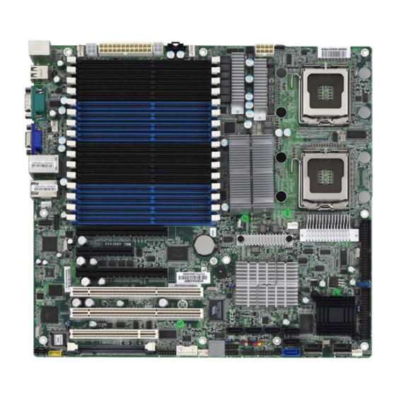
Page 8: Board Image
2.1- Board Image This picture is representative of the latest board revision available at the time of publishing. The board you receive may or may not look exactly like the above picture. http://www.tyan.com... -
Page 9: Block Diagram
2.2 - Block Diagram Tempest i5400PW S5397 Block Diagram http://www.tyan.com... -
Page 10: Board Parts, Jumpers And Connectors
This diagram is representative of the latest board revision available at the time of publishing. The board you receive may not look exactly like the above diagram. Jumper Legend OPEN - Jumper OFF, without jumper cover CLOSED – Jumper ON, with jumper cover http://www.tyan.com... - Page 11 COM2 Header J22/J23 1394 Header Front Panel Header TYAN Fan speed Header for Barebone TYAN TYFP2 Header (for TYAN Barebone Front Panel) TYAN LCM Header for Barebone USB Front Panel Header Audio Jack Header Aux. Power Header for TYAN Riser Card...
- Page 12 http://www.tyan.com...
- Page 13 J12: System Fan J19: CPUFAN0 J36: CPUFAN1 +12 V TAC H J21: System Fan J40: System Fan J37: TYAN TYFP2 Header for Barebone It is designed for BAREBONE use only Signal Signal LAN1 LED+ LAN1 LED- LAN2 LED+ LAN2 LED-...
- Page 14 http://www.tyan.com...
- Page 15 FAN9 TACH FAN10 TACH PWM SIG J8: IPMB Header Signal Signal SDAT SCLK J2: Aux. Power Header for TYAN Riser Card (M2061) Signal Signal 12 V G ND J38: LCM Header for Barebone It is designed for BAREBONE use only. Signal...
- Page 16 SATA4 SATA3 SATA5 SATA2 SATA1 SATA0 http://www.tyan.com...
- Page 17 J3: Onboard HD Audio Header TYAN does not provide cables for this header. The audio cable comes along with the 3rd party chassis supporting front audio jack module. Signal Signal MIC_L MIC_R PRESENT LINE_R MIC_JD SENSE LINE_L LINE_JD SATA0/1/2/3/4/5: SATA RAID Connector Connects to the Serial ATA ready drives via the Serial ATA cable.
- Page 18 JP7: FBD DIMM Voltage Select Jumper (Rev. 04 and beyond) Pin 1-2 Closed: 1.5V/1.55V (Default) Pin 2-3 Closed: 1.8V NOTE: Do not mix 1.5V/1.55V and 1.8V FB-DIMMs in one system. http://www.tyan.com...
- Page 19 JP4: Onboard 1394 Jumper Pin 1-2 Closed: Enable (Default) Pin 2-3 Closed: Disable JP5: PCI-X Speed Select Jumper Pin 2-3 Closed: 100MHz Pin 1-2 Closed: 133MHz (Default) JP6: Onboard SAS Jumper Pin 1-2 Closed: Enable (Default) Pin 2-3 Closed: Disable http://www.tyan.com...
-
Page 20: Tips On Installing Motherboard In Chassis
Some chassis’ include plastic studs instead of metal. Although the plastic studs are usable, TYAN recommends using metal studs with screws that will fasten the motherboard more securely in place. Below is a chart detailing what the most common motherboard studs look like and how they should be installed. -
Page 21: Installing The Processor(S)
2.5 - Installing the Processor(s) Your Tempest i5400PW S5397 supports the latest processor technologies from Intel. Check the TYAN website (http://www.tyan.com) for latest processor support. The Tempest i5400W S5397 is extended ATX form factor with proprietary CPU heatsink mounting hole locations. We provide the CPU heatsink mounting plate kit for users to adopt SSI EEB-3.51-and-beyond compliant chassis. - Page 22 Select the most suitable stand-off for your chassis, and fasten them onto the CPU heatsink mounting plate. They are the stand-offs to which you mount CPU heatsink later. Chassis Stand-off Height Mounting Plate Stand-off Height 3.5mm – 4.5mm 4.5mm – 5.5mm 5.5mm – 6.5mm http://www.tyan.com...
- Page 23 Install the mainboard into the chassis. Align CPU heatsink mounting holes with 8 stand-offs on the CPU heatsink mounting plate. Follow the processor installation process to install CPU(s). Place the CPU heatsink(s) on top of CPU(s) and fasten CPU heatsink(s) with screws. http://www.tyan.com...
- Page 24 Pull the locking lever out of it’s locked position and let it spring into the open position. Lift the metal cover to expose the socket interior and place the socket in as shown. Pin 1 http://www.tyan.com...
- Page 25 Close the cover and return the locking lever to its locked position. Repeat this procedure for the second processor socket. Turn the board upside down and insert the heat sink spring mechanism as shown. Turn the board the right way up again and screw the heat sink into place. http://www.tyan.com...
- Page 26 Try and apply a thin, even layer over the top of the processor. Align the heatsink with the four holes around the processor socket. Press the heatsink down until the four screws are securely seated in the holes. Use screw drive to secure the four screws. http://www.tyan.com...
-
Page 27: Installing The Memory
Before installing memory, ensure that the memory you have is compatible with the motherboard and processor. Only DDR2-800/667/533 Fully Buffer DIMM (FB DIMM) modules are required. Check the TYAN Web site at: www.tyan.com for details of the type of memory recommended for your motherboard. - Page 28 5VSB maximum (see Figure 1) of your power supply and make sure it is 4.5A or higher. Otherwise, the system will fail to boot up. Please refer to our web site at http://www.tyan.com for the recommended memory list. Figure 1...
- Page 29 Memory Installation Procedure Follow these instructions to install memory modules into the Tempest i5400PW S5397. Press the locking levers in the direction shown in the following illustration. Align the memory module with the socket. The memory module is keyed to fit only one way in the socket.
-
Page 30: Attaching Drive Cables
Attaching IDE Drive Cable Attaching the IDE drive cable is simple. These cables are “keyed” to only allow them to be connected in the correct manner. TYAN motherboards have two on- board IDE channels, each supporting two drives. The black connector designates the Primary channel, while the white connector designates the Secondary channel. - Page 31 TYAN has supplied two SATA cables and one SATA power adapter. If you are in need of other cables or power adapters please contact your place of purchase. The following pictures illustrate how to connect an SATA drive 1.SATA drive cable connection 2.
-
Page 32: Installing Add-In Cards
YOU MUST ALWAYS unplug the power connector from the motherboard before performing system hardware changes. NOTE Otherwise you may damage the board and/or expansion device. http://www.tyan.com... -
Page 33: Installing Optional So-Dimm Modules
The 200-pin vertical SO-DIMM connector can be used for TYAN M3295/M3296 expansion cards to provide such features as, additional SAS/SATA II or SCSI support. For details of available expansions cards, visit the TYAN website at http://www.tyan.com. To install a SO-DIMM expansion card: Open the spring levers as shown. -
Page 34: Connecting External Devices
The chart below illustrates the different LED states. 10/100/1000 Mbps LAN Link/Activity LED Scheme Left LED Right LED Link Green 10 Mbps Active Blinking Green Link Green Green 100 Mbps Active Blinking Green Green Link Green Yellow 1000 Mbps Active Blinking Green Yellow No Link http://www.tyan.com... -
Page 35: Installing The Power Supply
2.11 - Installing the Power Supply There are four power connectors on your Tempest i5400PW S5397. The Tempest i5400PW S5397 requires 5 x EPS +12V inputs. - 24-pin (PW2) – 12V - 8-pin (PW4) – 12V , 12V - 4-pin (PW1) – 12V - 4-pin (PW3) –... - Page 36 NOTE http://www.tyan.com...
-
Page 37: Chapter 3: Bios Setup
Changes settings. 3.1.2 Getting Help Pressing [F1] will display a small help window that describes the appropriate keys to use and the possible selections for the highlighted item. To exit the Help Window, press [ESC] or the [F1] key again. http://www.tyan.com... - Page 38 Chipset section unless you are absolutely sure of what you are doing. The Chipset defaults have been carefully chosen either by TYAN or your system manufacturer for best performance and reliability. Even a seemingly small change to the Chipset setup options may cause the system to become unstable or unusable.
-
Page 39: Bios Main Menu
Options: NONE / 360K, 5.25 in / 1.2 M, 5.25 in / 720 K, 3.5 in / 1.44 M, 3.5 in / 2.88 M, 3.5 in System Memory This display allows you to change the amount of system memory present on the system. http://www.tyan.com... - Page 40 Extended CHS or large mode, or it may be done using a different algorithm called LBA-assist translation. The translated geometry is still what is presented to the operating system for use in Int http://www.tyan.com...
- Page 41 Ultra DMA uses Cyclical Redundancy Checking (CRC), offering a new level of data protection. Options: Disabled / Mode 0 / Mode 1 / Mode 2 / Mode 3 / Mode 4 / Mode 5 http://www.tyan.com...
- Page 42 As such, it would be a waste of L2 cache bandwidth to cache the video BIOS instead of data that are more critical to the system's performance. In addition, if any http://www.tyan.com...
- Page 43 Options: Disabled / Write Through / Write Protect / Write Back Cache E000-E3FF/Cache E400-E7FF/Cache E800-EBFF/Cache EC00-EFFF These features allow you to control caching of Cache E000-E3FF/Cache E400- E7FF/Cache E800-EBFF/Cache EC00-EFFF memory Options: Disabled / Write Through / Write Protect / Write Back http://www.tyan.com...
- Page 44 If disabled, the BIOS will run the whole gamut of boot-up tests. It is recommended that you disable this feature when you boot up a new computer for the first time or whenever you install a new piece of hardware. This allows the http://www.tyan.com...
- Page 45 Disabled -> BIOS will not halt if there is any POST error. Options: Enabled / Disabled Extended Memory Testing Determines the tests that will be run on extended memory (memory above 1MB) during boot up. Options: Normal / Just zero it / None http://www.tyan.com...
-
Page 46: Advanced Menu
DOS if such a hard drive is present. Else, set this option to Other. Virtually, all modern hard disks have these characters so leave this option at DOS, unless you know otherwise. Options: DOS / Other http://www.tyan.com... - Page 47 Options: Disabled / Enabled Watchdog Timer Disable or select Watchdog Timer count mode. Options: Disabled / Second / Minute Count Watch dog timer value. Options: 1 – 255` NOTE: This item is hidden when Watchdog Timer is set to [Disabled]. http://www.tyan.com...
-
Page 48: Advanced Chipset Control
VMM through DRAM ACPI Tables. Options: Disabled / Enabled Crystal Beach Configure Enable Enable the configuration of memory mapped accesses to the Crystal Beach Configuration space located in Device 8, Fn 0 and Fn 1. Options: Enabled / Disabled SERR signal condition http://www.tyan.com... - Page 49 Options: Disabled / Enabled Enable Multimedia Timer This feature is used to enable/disable Multimedia Timer support. Options: Yes / No Snoop Filter Snoop Filter may reduce system bus traffic dependent on memory configuration and application used . Options: Enabled / Disabled http://www.tyan.com...
- Page 50 Enables or disables support for USB keyboards or mice. (Enable for use with a non-USB aware Operating System such as DOS or UNIX) Options: Enabled / Disabled Azalia Audio Enable/disable Azalia audio interface. Options: Auto / Disabled / Enabled http://www.tyan.com...
- Page 51 [Enhanced (non-AHCI) Mode]: SATA and PATA drives are auto-detected and placed in Native IDE mode. NOTE: Pre-Win2K’s OS’s do not work in Enhanced mode. Options: Compatible / Enhanced SATA RAID Enable This item allows you to enable the SATA RAID functionality. Options: Disabled / Enabled http://www.tyan.com...
- Page 52 SATA AHCI Enable This item allows you to enable the SATA AHCI functionality. Options: Disabled / Enabled http://www.tyan.com...
- Page 53 Options: Enabled / Disabled Execute Disable Bit Intel’s Execute Disable Bit functionality can help prevent certain classes of malicious buffer overflow attacks when combined with a supporting operating system. Execute Disable Bit allows the processor to classify areas in memory by http://www.tyan.com...
- Page 54 Options: Disabled / Enabled Processor Power Management Select the Processor Power Management. Options: Disabled / GV1/GV3 only Direct Cache Access Direct Cache Access is a system level protocol in a multi-processor system to improve I/O network performance. Options: Disabled / Enabled http://www.tyan.com...
- Page 55 This defines how the serial port is detected and configured. Options: Enabled / Disabled Base I/O Address This sets the base I/O address for serial port A/B. Options: 3F8 / 2F8 / 3E8 / 2E8 Interrupt This sets the interrupt for serial port A/B. Options: IRQ3 / IRQ4 http://www.tyan.com...
- Page 56 Mark DMI Events as Read Press [Enter] to mark all DMI events in the event log as read. Clear All DMI Event Logs Setting this to “Yes” will clear the DMI event log after rebooting. Options: No / Yes http://www.tyan.com...
-
Page 57: Hardware Monitor Configuration
FAN Fail LED Indicator When it is set to [Enabled], the LED will be on when the FAN failed. Options: Disabled / Enabled Chassis Intrusion Detect Enable/Disable: when chassis open event is detected, BIOS will record the event. Options: Enabled / Disabled http://www.tyan.com... - Page 58 ← → Exit Select Menu Enter Select Previous Values All items on this submenu can not be modified in user mode. Read only. NOTE: CPU temperature is read by Platform Environment Control Interface (PECI). Tmax=Thermal control circuit (TCC) Activation Temperature. http://www.tyan.com...
- Page 59 +12V 4.97V 3.29V +3.3V -11.90V -12V ↑↓ Help Select Item Change Values Setup Defaults ← → Sub-Menu Exit Select Menu Enter Select Previous Values All items on this submenu can not be modified in user mode. Read only. http://www.tyan.com...
- Page 60 This feature is used to indicate whether the console is connected directly to the system or a modem is used to connect. Options: Direct / Via modem Continue C.R. after POST This feature is used to enable console redirection after OS has loaded. Options: Off / On http://www.tyan.com...
-
Page 61: Security Menu
When enabled, the system will ask for a password at every boot. The system will continue booting only if the correct password is entered. If the wrong password is entered three times, the system will automatically shut down. Options: Disabled / Enabled http://www.tyan.com... -
Page 62: Power Menu
Wake/Sleep - This wakes the system from/puts the system to sleep. Options: On/Off / Wake/Sleep After Power Failure Specifies the mode of operation after the system recovers from a power loss. Options: Stay off / Last State / Power on http://www.tyan.com... -
Page 63: Boot Menu
Exit Select Menu Enter Select Previous Values The boot menu will list all bootable devices. Use <Enter> to expand or collapse devices with a ‘+’ or ‘-‘. Use <+> or <-> to arrange the priorities of all bootable devices. http://www.tyan.com... -
Page 64: Exit Menu
Exit Discarding Changes This exits BIOS setup after discarding the changes made. Load Setup Defaults Loads the factory default values. Discard Changes Discards all changes made without exiting BIOS setup. Save Changes Saves all changes made without exiting BIOS. http://www.tyan.com... -
Page 65: Chapter 4: Diagnostics
The most common type of error is a memory error. Before contacting your vendor or TYAN Technical Support, be sure that you note as much as you can about the beep code length and order that you experience. Also, be ready with information regarding add-in cards, drives and O/S to speed the support process and come to a quicker solution. -
Page 66: Phoenix Bios Post Code
Initialize POST Memory Test extended memory Manager address lines Clear 512 KB base RAM Jump to UserPatch1 1-3-4-1. RAM failure on Configure advanced cache address registers 1-3-4-3. RAM failure on Initialize Multi Processor data bits of low byte of APIC http://www.tyan.com... - Page 67 Initialize hard-disk PnPnd dual CMOS controllers (optional) Initialize local-bus hard-disk Initialize notebook docking controllers (optional) Jump to UserPatch2 Initialize notebook docking late Build MPTABLE for multi- Force check (optional) processor boards Install CD ROM for boot Extended checksum http://www.tyan.com...
- Page 68 Initialize PIC and DMA Initialize System Management Mode Initialize Memory type Output one beep before boot Initialize Memory size Boot to Mini DOS Shadow Boot Block Clear Huge Segment System memory test Boot to Full DOS Initialize interrupt vectors http://www.tyan.com...
-
Page 69: Appendix: Smdc Information
It enables any IT Manager by providing multi-interfaces to access the hardware remotely and perform monitor, control and diagnose activities effectively. TYAN SMDC is not a peripheral card. Unlike regular peripheral card such as AGP card, Network card or SCSI card, SMDC does not require any hardware specific driver. - Page 70 Features of TYAN Server Management Monitor various system components remotely - such as fans, processor temperature, and more Remote power on and power off Console redirect -the ability to view system remotely Alert and error actions -such as audible beep, e-mail, power down and reboot...
-
Page 71: Glossary
While this improves system performance --- reading to or writing from a disk drive a single time is much faster than doing so repeatedly --- there is also the possibility of losing your data should the system crash. Information stored in a buffer is temporarily stored, not permanently saved. http://www.tyan.com... - Page 72 DMA (Direct Memory Access): channels that are similar to IRQs. DMA channels allow hardware devices (like soundcards or keyboards) to access the main memory without involving the CPU. This frees up CPU resources for other tasks. As with http://www.tyan.com...
- Page 73 EEPROM (Electrically Erasable Programmable ROM): also called Flash BIOS, is a ROM chip which can, unlike normal ROM, be updated. This allows you to keep up with changes in the BIOS programs without having to buy a new chip. TYAN’s BIOS updates can be found at http://www.tyan.com EMRL: Embedded RAID Logic.
- Page 74 ISA bus. Local buses are those which operate within a single system (as opposed to a network bus, which connects multiple systems). PCI PIO (PCI Programmable Input/Output) modes: the data transfer modes used by IDE drives. These modes use the CPU for data transfer (in contrast, DMA http://www.tyan.com...
- Page 75 RAID subsystem. The RAIDIOS circuit allows an I/O Processor (either embedded on the motherboard or on an add-in card) to configure the I/O controller and service the I/O controller’s interrupts. The I/O controller and the I/O http://www.tyan.com...
- Page 76 (chassis, power supplies, and racks) to promote and support server industry growth. Standby mode: in this mode, the video and hard drives shut down; all other devices continue to operate normally. http://www.tyan.com...
- Page 77 CPUs without damaging the sensitive CPU pins. The CPU is lightly placed in an open ZIF socket, and a lever is pulled down. This shift the processor over and down, guiding into the board and locking it into place. http://www.tyan.com...
- Page 78 NOTE http://www.tyan.com...
-
Page 79: Technical Support
Return Merchandise Authorization (RMA) number. The RMA number should be prominently displayed on the outside of the shipping carton and the package should be mailed prepaid. TYAN will pay to have the board shipped back to you. - Page 80 Danger of explosion if battery is incorrectly replaced. Replace only with the same or equivalent type recommended by manufacturer. Dispose of used battery according to manufacturer instructions and in accordance with your local regulations. Document #: D1904-130 http://www.tyan.com...
Need help?
Do you have a question about the Tempest i5400PW and is the answer not in the manual?
Questions and answers