Table of Contents
Advertisement
///
Tempest i5000XT
S2696
Version 1.30
Copyright
Copyright © TYAN Computer Corporation, 2006. All rights reserved. No part of
this manual may be reproduced or translated without prior written consent from
TYAN Computer Corp.
Trademark
All registered and unregistered trademarks and company names contained in
this manual are property of their respective owners including, but not limited to
the following.
TYAN, Tempest i5000XT are trademarks of TYAN Computer Corporation.
Intel, Greencreek, and combinations thereof are trademarks of Intel Corporation.
Phoenix, Phoenix-Award BIOS are trademarks of Phoenix Technologies.
Notice
Information contained in this document is furnished by TYAN Computer
Corporation and has been reviewed for accuracy and reliability prior to printing.
TYAN assumes no liability whatsoever, and disclaims any express or implied
warranty, relating to sale and/or use of TYAN products including liability or
warranties relating to fitness for a particular purpose or merchantability. TYAN
retains the right to make changes to product descriptions and/or specifications
at any time, without notice. In no event will TYAN be held liable for any direct or
indirect, incidental or consequential damage, loss of use, loss of data or other
malady resulting from errors or inaccuracies of information contained in this
document.
1
Advertisement
Table of Contents

Related Manuals for TYAN Tempest i5000XT S2696


Summary of Contents for TYAN Tempest i5000XT S2696
- Page 1 In no event will TYAN be held liable for any direct or indirect, incidental or consequential damage, loss of use, loss of data or other malady resulting from errors or inaccuracies of information contained in this document.
-
Page 2: Table Of Contents
Table of Contents Check the box contents! Chapter 1: Introduction Congratulations…………………………………………………………… Hardware Specifications………………………………………………… Chapter 2: Board Installation Board Image……………………………………………………………… Block Diagram……………………………………………………………. Board Parts, Jumpers and Connectors………………………………... 10 Tips on Installing Motherboard in Chassis…………………………….. 19 Installing the Processor(s)………………………………....... 20 Installing the Memory……………………………………………………. Attaching Drive Cables………………………………………………….. -
Page 3: Check The Box Contents
2 x SAS cable 1 x Tempest i5000XT user’s manual 1 x Tempest i5000XT Quick Reference guide 1 x TYAN driver CD 1 x I/O shield If any of these items are missing, please contact your vendor/dealer for replacement before continuing with the installation process. -
Page 5: Chapter 1: Introduction
SAS ports based on the integrated LSI SAS controller. It's ideally design to provide a versatile workstation platform. Remember to visit TYAN’s Website at http://www.TYAN.com. There you can find information on all of TYAN’s products with FAQs, online manuals and BIOS upgrades. 1.2 - Hardware Specifications... - Page 6 Raid support: IM/IME/IS Software Specifications OS (Operating System) Support Microsoft Windows 2000 Pro Microsoft Windows XP Pro (32-bit) Microsoft Windows XP Pro (64-bit) TYAN reserves the right to add support or discontinue support for any OS with or without notice.
-
Page 7: Chapter 2: Board Installation
Unplug the power from your computer power supply and then touch a safely grounded object to release static charge (i.e. power supply case). For the safest conditions, TYAN recommends wearing a static safety wrist strap. (2) Hold the motherboard by its edges and do not touch the bottom of the board, or flex the board in any way. -
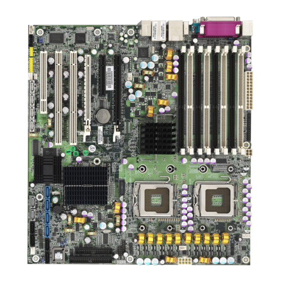
Page 8: Board Image
2.1- Board Image This picture is representative of the latest board revision available at the time of publishing. The board you receive may or may not look exactly like the above picture. -
Page 9: Block Diagram
2.2 - Block Diagram S2696 Block Diagram... -
Page 10: Board Parts, Jumpers And Connectors
2.3 - Board Parts, Jumpers and Connectors This diagram is representative of the latest board revision available at the time of publishing. The board you receive may not look exactly like the above diagram. - Page 11 Jumper Legend OPEN - Jumper OFF, without jumper cover CLOSED – Jumper ON, with jumper cover Jumper/Connector Function Internal Buzzer Jumper Audio Front Panel JP7/JP8 LAN Enable/Disable Jumper CMOS Clear Jumper JP10 PS/2 Devices Wake up Enable Jumper JP14 FW Write Protect Jumper JP16 PCI-X Frequency Setting Jumper JP19...
- Page 12 JP1: Internal Buzzer Enable/Disable Jumper Use this jumper to disable the onboard internal Buzzer. Use this jumper to enable the onboard internal Buzzer. (Default)
- Page 13 E50: CMOS Clear Jumper Use this jumper when you have forgotten your system/setup password or need to clear the system BIOS settings. Normal (Default) How to clear the CMOS data Power off system and disconnect the power supply from the AC source Use jumper cap to close pin_2 and 3 for several seconds to clear the CMOS Replace the jumper cap to close pin_1 and 2...
- Page 14 JP14: FWH Write Protect Jumper Use this jumper to disable the FWH write protect. (Default) Use this jumper to enable the FWH write protect.
- Page 15 JP10: PS/2 Devices Wake up Jumper Use this jumper to disable the PS/2 devices from waking up. Use this jumper to enable the waking up of the PS/2 devices. (Default) JP19: Chassis Intrusion Jumper Use this jumper to disable the system chassis intrusion alarm.
- Page 16 JP23: BIOS Recovery Jumper No BIOS recovery function (Default) BIOS will be forced into recovery. BIOS image will be loaded from floppy.
- Page 17 JP16: PCI-X Frequency Setting Jumper Use this jumper to set the PCI-X frequency at 133MHz. (Default) Use this jumper to set the PCI-X frequency at 100MHz. Use this jumper to set the PCI-X frequency at 66MHz. P17: Intel HD Audio Digital Header Intel HD Audio Digital Header is used to support one HD Codec on a cabled up card.
- Page 18 SAS 0/1/2/3/4/5/6/7: SAS Connector Connects to the SAS ready drives via the SAS cable or SATA ready drives via the SATA cable You may use these eight SAS ports to have the support of RAID IM, IME and IS through the embedded LSI1068E chip.
-
Page 19: Tips On Installing Motherboard In Chassis
Some chassis’ include plastic studs instead of metal. Although the plastic studs are usable, TYAN recommends using metal studs with screws that will fasten the motherboard more securely in place. -
Page 20: Installing The Processor(S)
2.5 - Installing the Processor(s) Your S2696 supports the latest processor technologies from Intel. Check the TYAN website for latest processor support: http://www.tyan.com Processor Installation The processor should be installed carefully. Make sure you are wearing an antistatic strap and handle the processor as little as possible. - Page 21 Lift the metal cover to expose the socket interior and place the socket in as shown. Pin 1 Close the cover and return the locking lever to its locked position. Repeat this procedure for the second processor socket. Turn the board upside down and insert the heat sink spring mechanism as shown.
- Page 22 Repeat this procedure for the second processor. Cooling Fan Installation After you have installed the processor, the heatsink should be installed to ensure that the processor runs efficiently and does not overheat. Use heatsink for best results. Follow these instructions to install the heatsink shown. Apply some (a little will work, more doesn’t equal better performance) thermal compound to the top of the processor.
-
Page 23: Installing The Memory
Before installing memory, ensure that the memory you have is compatible with the motherboard and processor. Only DDR2-533/667 FB-DIMM modules are required. Check the TYAN Web site at: www.tyan.com for details of the type of memory recommended for your motherboard. - Page 24 Memory Installation Procedure Follow these instructions to install memory modules into the S2696. Press the locking levers in the direction shown in the following illustration. Align the memory module with the socket. The memory module is keyed to fit only one way in the socket. Key slot Seat the module firmly into the socket by gently pressing down until it sits flush with the socket.
-
Page 25: Attaching Drive Cables
Attaching IDE Drive Cable Attaching the IDE drive cable is simple. These cables are “keyed” to only allow them to be connected in the correct manner. TYAN motherboards have two on-board IDE channels, each supporting two drives. The black connector designates the Primary channel, while the white connector designates the Secondary channel. - Page 26 Tyan has supplied two SATA cables and one SATA power adapter. If you are in need of other cables or power adapters please contact your place of purchase. The following pictures illustrate how to connect an SATA drive 1.SATA drive cable connection 2.
-
Page 27: Installing Add-In Cards
2.8 - Installing Add-In Cards Before installing add-in cards, it’s helpful to know if they are fully compatible with your motherboard. For this reason, we’ve provided the diagrams below, showing the slots that appear on your motherboard. PCI-E X 16 S lot PCI-E x16 slot PCI-E x8 slot PCI-E X 8 S lo t... -
Page 28: Connecting External Devices
2.9 - Connecting External Devices The following diagrams will detail the rear port stack for the S2696 motherboard: PS/2 Mouse/Keyboard Audio LAN2 LAN1 Parallel Port USB x 2 USB x 2 1394 Port SPDIF SPDIF Serial Port NOTE: Peripheral devices can be plugged straight into any of these ports but software may be required to complete the installation. -
Page 29: Installing The Power Supply
2.10 - Installing the Power Supply There are three power connectors on your S2696. The S2696 requires that you have an EPS12V power supply that has a 24-pin, an 8-pin power connector and a 4-pin 12V power connector. Please be aware that ATX 2.x, ATX12V and ATXGES power supplies may not be compatible with the board and can damage the motherboard and/or CPU(s). -
Page 30: Chapter 3: Bios Setup
Chapter 3: BIOS Setup 3.1. About the BIOS The BIOS is the basic input/output system, the firmware on the motherboard that enables your hardware to interface with your software. The BIOS determines what a computer can do without accessing programs from a disk. The BIOS contains all the code required to control the keyboard, display screen, disk drives, serial communications, and a number of miscellaneous functions. - Page 31 Chipset section unless you are absolutely sure of what you are doing. The Chipset defaults have been carefully chosen either by TYAN or your system manufacturer for best performance and reliability. Even a seemingly small change to the Chipset setup options may cause the system to become unstable or unusable.
-
Page 32: Bios Main Menu
3.2 BIOS Main Menu In this section, you can alter general features such as the date and time, as well as access to the IDE configuration options. Note that the options listed below are for options that can directly be changed within the Main Setup screen. PhoenixBIOS Setup Utility Main Advanced... - Page 33 System Memory This display allows you to change the amount of system memory present on the system. Extended Memory This displays/allows you to change the amount of extended memory present on the system. 3.2.1 IDE Channel 0/1 Setup Computer detects IDE drive type from drive C to drive F. Press Enter on any of the Channel 0, Channel 1 options to view advanced details of the corresponding drive.
- Page 34 Multi-Sector Transfers This option allows you to specify the number of sectors per block for multiple sector transfers. Disabled/ 2 Sectors / 4 Sectors / 8 Sectors / 16 Sectors LBA Mode Control Enables or disables LBA Mode. When LBA is turned on, the BIOS will enable geometry translation. This translation may be done in the same way that it is done in Extended CHS or large mode, or it may be done using a different algorithm called LBA-assist translation.
- Page 35 3.2.2 Memory Cache This setting allows you to tweak the various cache settings for optimal performance of your system. Press Enter to display the various cache settings. PhoenixBIOS Setup Utility Main Advanced Security Power Boot Exit Memory Cache Item Specific Help Controls caching of system BIOS area.
- Page 36 As such, it would be a waste of L2 cache bandwidth to cache the video BIOS instead of data that are more critical to the system's performance. In addition, if any program writes into this memory area, it will result in a system crash. So, it is recommended that you write protect this area for optimal system performance.
- Page 37 3.2.3 Board Information This displays motherboard and BIOS version information. PhoenixBIOS Setup Utility Main Advanced Security Power Boot Exit Board Information Item Specific Help Bios Version Bios Build Date Board Mfg Board Help Select Item Change Values Setup Defaults ↑↓ Exit Select Menu Enter...
-
Page 38: Advanced Menu
3.3 Advanced Menu This section facilitates configuring advanced BIOS options for your system. PhoenixBIOS Setup Utility Main Advanced Security Power Boot Exit Item Specific Help Hardware Monitoring BIOS Event Logging Hardware monitoring Advanced Chipset Control configuration Advanced Processor Options Diskette Controller ATA Controller LSI SAS Interface Integrated Network Interface... - Page 39 BIOS feature and then reboot your computer. The new ESCD should resolve the conflict and allow the operating system to load normally. Please note that the BIOS will automatically reset it to the default setting of No after reconfiguring the new ESCD. So, there is no need for you to manually disable this feature after rebooting.
- Page 40 3.3.1 Hardware Monitoring This displays critical system parameters like CPU speed, fan speeds, voltage levels and CPU temperature. PhoenixBIOS Setup Utility Main Advanced Security Power Boot Exit Hardware Monitoring Item Specific Help FAN Speed Control [Full Speed] CPU Temp Reading [Auto] Realtime sensors Help...
- Page 41 3.3.1.1 Realtime Sensors This screen contains the information from motherboard hardware monitor sensors, such as temperature and fan speed. PhoenixBIOS Setup Utility Main Advanced Security Power Boot Exit Realtime Sensors Item Specific Help CPU0 Temperature CPU1 Temperature CPU0 Fan (Fan0) xxxx CPU1 Fan (Fan1) xxxx...
- Page 42 3.3.2 BIOS Event Logging PhoenixBIOS Setup Utility Main Advanced Security Power Boot Exit BIOS Event Logging Item Specific Help BIOS Event Logging: [Enabled] View BIOS event log: [Enter] Clear BIOS Event Log: [Disabled] Help Select Item Change Values Setup Defaults ↑↓...
- Page 43 3.3.3 Advanced Chipset Control PhoenixBIOS Setup Utility Main Advanced Security Power Boot Exit Advanced Chipset Control Item Specific Help Crystal Beach Configuration Enable: [Disabled] SERR signal condition: [Single bit] 4GB PCI Hole Granularity: [256MB] Memory Branch Mode: [Interleave] Branch 0 Rank Interleave: [4:1] Branch 0 Rank Sparing: [Disabled]...
- Page 44 Disabled / Enabled Force ITK Config Clocking This feature is used to enable/disable FBD configuration for ITK test suite. Disabled / Enabled High Precision Event Timer: This feature is used to enable/disable Multimedia Timer support. Disabled / Enabled Snoop filter This item is used to enable the snoop filter.
- Page 45 3.3.4 Advanced Processor Options This section allows you to fine-tune the processor options. PhoenixBIOS Setup Utility Main Advanced Security Boot Exit Advanced Processor Options Item Specific Help [Enabled] Numbers of Stop Grant [Enabled] Hyperthreading: [Disabled] Intel® Virtualization Technology [Disabled] Machine Checking [Enabled] C1 Enhanced Mode [Disabled]...
- Page 46 processing throughput. Hyper-Threading Technology is a form of simultaneous multi-threading technology (SMT) where multiple threads of software applications can be run simultaneously on one processor. This is achieved by duplicating the architectural state on each processor, while sharing one set of processor execution resources.
- Page 47 3.3.6 ATA Controller This screen contains the configuration of the ATA controller. PhoenixBIOS Setup Utility Main Advanced Security Power Boot Exit ATA Controller Item Specific Help Parellel ATA: [Enabled] Serial ATA: [Enabled] SATA Controller Mode Option: [Enhanced] SATA RAID Enable: [Disabled] SATA AHCI Enabel: [Enabled]...
- Page 48 3.3.7 LSI SAS Interface This screen contains the configuration of the LSI SAS interface. PhoenixBIOS Setup Utility Main Advanced Security Power Boot Exit LSI SAS Interface Item Specific Help LSI SAS Controller: [Enabled] Option ROM Scan: [Enabled] Help Select Item Change Values Setup Defaults ↑↓...
- Page 49 3.3.8 Integrated Network Interface This screen contains the configuration of the integrated network interface. PhoenixBIOS Setup Utility Main Advanced Security Power Boot Exit Integrated Network Interface Item Specific Help LAN Port0: [Enabled] LAN Port1: [Enabled] Option ROM Scan [Disabled] Help Select Item Change Values Setup Defaults...
- Page 50 3.3.9 Integrated Audio PhoenixBIOS Setup Utility Main Advanced Security Power Boot Exit Integrated Audio Item Specific Help Integrated Audio [Auto] Help Select Item Change Values Setup Defaults ↑↓ Exit Select Menu Enter Select Save and Exit ← → Sub-Menu 3.3.10 Integrated 1394 PhoenixBIOS Setup Utility Main Advanced...
- Page 51 3.3.11 Integrated USB This screen contains the configuration of the integrated USB. PhoenixBIOS Setup Utility Main Advanced Security Power Boot Exit Integrated USB Item Specific Help Integrated USB1.1 [Enabled] Integrated USB2.0 [Enabled] Legacy USB Support [Enabled] Help Select Item Change Values Setup Defaults ↑↓...
- Page 52 3.3.10 I/O Device Configuration PhoenixBIOS Setup Utility Main Advanced Security Boot Exit I/O Device Configuration Item Specific Help Serial port A: [Enabled] [3F8] Base I/O Address: Interrupt: [IRQ 3] Parallel port: [Enabled] [ECP] Mode: Base I/O Address [378] Interrupt: [IRQ 7] DMA channel: [DMA 3] Help...
- Page 53 Generally, because of its FIFOs and the DMA channel it uses, ECP is good for large data transfers (useful for scanners and printers). On the other hand, EPP is better with links that switch directions frequently (like parallel port drives). Output only / Bi-directional / EPP / ECP Base I/O Address Set the base I/O address for parallel port.
- Page 54 3.3.11 PCI Configuration This screen contains the additional setup menus to configure PCI devices. PhoenixBIOS Setup Utility Main Advanced Security Boot Exit PCI Configuration Item Specific Help PCI Device, Slot #1 PCI Device, Slot #2 PCI Device, Slot #3 PCI Device, Slot #4 PCI Device, Slot #5 PCI Device, Slot #6 Help...
- Page 55 3.3.11.1 PCI Device, Slot # 1/2/3/4/5/6 Sub-Menu These screens contain the setup items for configuring the specific PCI device. PhoenixBIOS Setup Utility Main Advanced Security Boot Exit PCI Device, Slot #1/2/3/4/5/6 Item Specific Help Option ROM Scan [Enabled] Latency Timer [Default] Help Select Item...
-
Page 56: Security Menu
3.4 Security Menu These settings allow you to configure the security options for your system. PhoenixBIOS Setup Utility Main Advanced Security Power Boot Exit Item Specific Help Supervisor Password Is: Clear Clear User Password Is: [Enter] Set Setup Password [Enter] Set User Password [Normal] Fixed disk boot sector... - Page 57 BIOS Write Protect This item is used to configure the writing protection of BIOS flash memory. When set to enabled, the BIOS flash memory will be written protected. Disabled / Enabled Cabinet Monitoring This item is used to configure the monitoring of system’s housing. When enabled, the system’s housing is monitored.
-
Page 58: Power Menu
3.5 Power Menu PhoenixBIOS Setup Utility Main Advanced Security Power Boot Exit Item Specific Help ACPI Save to RAM: [Enabled] [Power on] After Power Failure: Help Select Item Change Values Setup Defaults ↑↓ Exit Select Menu Enter Select Save and Exit ←... -
Page 59: Boot Menu
3.6 Boot Menu Use this screen to select options for the Boot Settings Configuration. PhoenixBIOS Setup Utility Main Advanced Security Power Boot Exit Item Specific Help Halt on POST Erros: [Enabled] [Enabled] Summary screen: [Disabled] Quiet Boot: [Enabled] QuickBoot Mode: Boot Device Priority Help Select Item... - Page 60 3.6.1 Boot Device Priority Use this screen to select options for the Boot Settings Configuration. PhoenixBIOS Setup Utility Main Advanced Security Power Boot Exit Boot Device Priority Item Specific Help Keys used to view or configure devices: <Enter> expands or 1: Legacy Floppy Drives collapses devices with a + or –...
-
Page 61: Exit Menu
3.7 Exit Menu These settings set the exit options on your system. PhoenixBIOS Setup Utility Main Advanced Security Boot Exit Item Specific Help Exit Saving Changes Exit system Setup and Exit Discarding Changes save your changes to Load Setup Defaults CMOS. -
Page 62: Chapter 4: Diagnostics
The most common type of error is a memory error. Before contacting your vendor or TYAN Technical Support, be sure that you note as much as you can about the beep code length and order that you experience. Also, be ready with information regarding add-in cards, drives and O/S to speed the support process and come to a quicker solution. -
Page 63: Bios Post Code
4.3 - BIOS Post Code Code Beeps / Description Code Beeps / Description Verify Real Mode Test CPU bus-clock frequency Disable Non-Maskable Initialize Phoenix Dispatch Interrupt (NMI) Manager Get CPU type Warm start shut down Initialize system hardware Shadow system BIOS ROM Initialize chipset with initial Autosize cache POST values... - Page 64 system BIOS shadow caches 1-4-1-1. RAM failure on Setup System Management data bits of high byte of Mode (SMM) area memory bus Code Beeps / Description Code Beeps / Description Display external L2 cache Check key lock size Load custom defaults Initialize Typematic rate (optional) Display shadow-area...
- Page 65 register Fixup Multi Processor table BIOS Boot Block 1-2. Search for option BIOS Boot Block ROMs. Check for SMART Drive Initialize the CPU (optional) Shadow option ROMs Initialize system timer Set up Power Management Initialize system I/O Initialize security engine Check force recovery boot (optional) Enable hardware interrupts...
-
Page 66: Appendix I: Smdc Information
It enables any IT Manager by providing multi-interfaces to access the hardware remotely and perform monitor, control and diagnose activities effectively. Tyan SMDC is not a peripheral card. Unlike regular peripheral card such as AGP card, Network card or SCSI card, SMDC does not require any hardware specific driver. - Page 67 Features of Tyan Server Management Monitor various system components remotely - such as fans, processor temperature, and more Remote power on and power off Console redirect -the ability to view system remotely Alert and error actions -such as audible beep, e-mail, power down and reboot...
-
Page 68: Appendix Ii: How To Make A Driver Diskette
Appendix II: How to Make a Driver Diskette Follow the steps below to make a driver diskette from the TYAN driver CD provided. Start the system and insert the TYAN CD into the CD-ROM drive to boot from CD. You will see the following menu. Then press [1] and [Enter] to boot the system to Tyan diskette maker. - Page 69 Follow the instruction on menu to insert a diskette and press [ENTER]. Please insert a formatted diskette into A:/ and press [ENTER] Writing image to drive A: Track: 36 Hoad: 8 Sector: 1 Using "ESC" key to quit the Tyan diskette maker. The system will automatically restart.
-
Page 70: Glossary
Glossary ACPI (Advanced Configuration and Power Interface): a power management specification that allows the operating system to control the amount of power distributed to the computer’s devices. Devices not in use can be turned off, reducing unnecessary power expenditure. AGP (Accelerated Graphics Port): a PCI-based interface which was designed specifically for demands of 3D graphics applications. - Page 71 Bus: a data pathway. The term is used especially to refer to the connection between the processor and system memory, and between the processor and PCI or ISA local buses. Bus mastering: allows peripheral devices and IDEs to access the system memory without going through the CPU (similar to DMA channels).
- Page 72 EEPROM (Electrically Erasable Programmable ROM): also called Flash BIOS, is a ROM chip which can, unlike normal ROM, be updated. This allows you to keep up with changes in the BIOS programs without having to buy a new chip. TYAN’s BIOS updates can be found at http://www.tyan.com EMRL: Embedded RAID Logic.
- Page 73 IDE (Integrated Device/Drive Electronics): a simple, self-contained HDD interface. It can handle drives up to 8.4 GB in size. Almost all IDEs sold now are in fact Enhanced IDEs (EIDEs), with maximum capacity determined by the hardware controller. IDE INT (IDE Interrupt): a hardware interrupt signal that goes to the IDE. I/O (Input/Output): the connection between your computer and another piece of hardware (mouse, keyboard, etc.) Initial Program Load (IPL): a feature built into BBS-compliant devices, describing...
- Page 74 PCI-to-PCI bridge: allows you to connect multiple PCI devices onto one PCI slot. Pipeline burst SRAM: a type of RAM that can maintain it’s data as long as power is provided to the memory chips. In this configuration, SRAM requests are pipelined, which means that larger packets of data are sent to the memory at one time, and acted upon quickly.
- Page 75 RAM (Random Access Memory): technically refers to a type of memory where any byte can be accessed without touching the adjacent data, is often used to refer to the system’s main memory. This memory is available to any program running on the computer.
- Page 76 UltraDMA-33/66/100: a fast version of the old DMA channel. UltraDMA is also called UltraATA. Without proper UltraDMA controller, your system cannot take advantage of higher data transfer rates of the new UltraDMA/UltraATA hard drives. USB (Universal Serial Bus): a versatile port. This one port type can function as a serial, parallel, mouse, keyboard or joystick port.
-
Page 77: Technical Support
Return Merchandise Authorization (RMA) number. The RMA number should be prominently displayed on the outside of the shipping carton and the package should be mailed prepaid. TYAN will pay to have the board shipped back to you. - Page 78 Notice for the USA Compliance Information Statement (Declaration of Conformity Procedure) DoC FCC Part 15: This device complies with part 15 of the FCC Rules Operation is subject to the following conditions: This device may not cause harmful interference, and This device must accept any interference received including interference that may cause undesired operation.
Need help?
Do you have a question about the Tempest i5000XT S2696 and is the answer not in the manual?
Questions and answers