Table of Contents
Advertisement
Quick Links
///
Tempest i5100X
S5375
Version 1.2
Copyright
®
Copyright © 2008 MiTAC International Corporation. All rights reserved. TYAN
is a
registered trademark of MiTAC International Corporation.
Trademark
All registered and unregistered trademarks and company names contained in this
manual are property of their respective owners including, but not limited to the
following.
®
TYAN
, Tempest i5100X are trademarks of MiTAC International Corporation.
®
Intel
5100/5200/5400 Series and combinations thereof are trademarks of Intel
Corporation.
AMI, AMI BIOS are trademarks of AMI Technologies.
Microsoft, Windows are trademarks of Microsoft Corporation.
SuSE is a trademark of Novell.
IBM, PC, AT, and PS/2 are trademarks of IBM Corporation.
Notice
Information contained in this document is furnished by MiTAC International
Corporation and has been reviewed for accuracy and reliability prior to printing.
MiTAC assumes no liability whatsoever, and disclaims any express or implied
warranty, relating to sale and/or use of MiTAC products including liability or
warranties relating to fitness for a particular purpose or merchantability. MiTAC
retains the right to make changes to product descriptions and/or specifications at
any time, without notice. In no event will MiTAC be held liable for any direct or
indirect, incidental or consequential damage, loss of use, loss of data or other
malady resulting from errors or inaccuracies of information contained in this
document.
1
http://www.tyan.com
Advertisement
Table of Contents

Related Manuals for TYAN Tempest i5100X S5375


Summary of Contents for TYAN Tempest i5100X S5375
- Page 1 Tempest i5100X S5375 Version 1.2 Copyright ® Copyright © 2008 MiTAC International Corporation. All rights reserved. TYAN is a registered trademark of MiTAC International Corporation. Trademark All registered and unregistered trademarks and company names contained in this manual are property of their respective owners including, but not limited to the following.
-
Page 2: Table Of Contents
Finishing up Chapter 3: BIOS Setup BIOS Main Menu Advanced Menu PCI PnP Menu Boot Menu Security Menu Chipset Menu Exit Menu Chapter 4: Diagnostics Beep Codes Flash Utility AMI BIOS Post Code Appendix: SMDC Information Glossary Technical Support http://www.tyan.com... -
Page 3: Check The Box Contents
1x Serial Port Cable 1 x S5375 user’s manual 1 x S5375 Quick Reference guide ® 1 x TYAN driver CD 1 x I/O shield 2 x CPU Back Plane If any of these items are missing, please contact your vendor/dealer for replacement before continuing with the installation process. - Page 4 NOTE http://www.tyan.com...
-
Page 5: Chapter 1: Introduction
LAN controllers, built-in 32MB XGI Z9S video plus six SATA2 ports, the S5375 offers exceptional performance and versatile solution for your server / Workstation. Remember to visit TYAN’s Website at http://www.tyan.com. There you can find information on all of TYAN’s products with FAQs, online manuals and BIOS upgrades. 1.2 - Hardware Specifications... - Page 6 •CEB footprint (10.5” x 12”) for LAN LED and ID LED/Switch •2x7 pin Fan header Power •One (1) SO-DIMM connector for •ATX 12V ® •Universal 24-pin +8-pin power optional TYAN SMDC M3295-2 / M3296 connectors Integrated SATA Controller Regulatory (ICH9R) •FCC Class B (DoC) •Supports six (6) SATA2 ports...
-
Page 7: Chapter 2: Board Installation
Chapter 2: Board Installation You are now ready to install your motherboard. The mounting hole pattern of the Tempest i5100X S5375 matches the SSI CEB specification. Before continuing with installation, confirm that your chassis supports an SSI CEB motherboard. How to install our products right… the first time The first thing you should do is reading this user’s manual. -
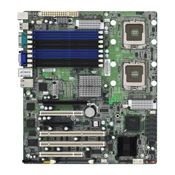
Page 8: Board Image
2.1- Board Image Tempest i5100X S5375AG2NR This picture is representative of the latest board revision available at the time of publishing. The board you receive may or may not look exactly like the above picture. http://www.tyan.com... - Page 9 Tempest i5100X S5375G2NR-1U This picture is representative of the latest board revision available at the time of publishing. The board you receive may or may not look exactly like the above picture. http://www.tyan.com...
-
Page 10: Block Diagram
2.2 - Block Diagram Tempest i5100X S5375AG2NR Block Diagram http://www.tyan.com... - Page 11 Tempest i5100X S5375G2NR-1U Block Diagram http://www.tyan.com...
-
Page 12: Board Parts, Jumpers And Connectors
This diagram is representative of the latest board revision available at the time of publishing. The board you receive may not look exactly like the above diagram. Jumper Legend OPEN - Jumper OFF, without jumper cover CLOSED – Jumper ON, with jumper cover http://www.tyan.com... - Page 13 COM2 COM2 Header SATA0~SATA5 Serial ATA Connector 24-pin Power Connector (EPS12V) 8-pin Power Connector (EPS12V) ® Aux. Power Header for TYAN Riser Card (M2061) CPUFAN1/CPUFAN2/ 4-pin Power Connector with Tachometer FAN1/FAN2/FAN3 VGA Enable/Disable Jumper Clear CMOS Jumper PCI-X Speed Select Jumper...
- Page 14 SATA0 SATA1 SATA2 SATA3 SATA4 SATA5 http://www.tyan.com...
- Page 15 J2: CD_IN Connector (S5375AG2NR only) Signal Signal J4: Front Panel Audio Connector (S5375AG2NR only) ® TYAN does not provide cables for this header. Signal Signal MIC1_LN MIC1_RN reserved FRONT_RN MIC_JD SENSE FRONT_LN LINE_JD J10: Chassis Intrusion Connector Use this header to connect with the front intruder button which indicates the warning message when the system cover is opened.
- Page 16 COM2 http://www.tyan.com...
- Page 17 COM2: COM2 Header Use these pin definitions to connect a port to COM2. ® *TYAN does not provide cables for this header. It is designed for barebone use only. Signal Signal J11: Fan Board Connector for Barebone It is designed for barebone use only.
- Page 18 CPUFAN1 FAN1 CPUFAN2 FAN3 FAN2 JP5: PCI-X Speed Select Jumper (S5375AG2NR only) Pin 1-2 Closed: 133MHz (Default) Pin 2-3 Closed: 100MHz max. http://www.tyan.com...
- Page 19 Power off system and disconnect power (Default) supply from AC source Use jumper cap to close Pin_2 and 3 for several seconds to Clear CMOS Replace jumper cap to close Pin_1 and 2 Reconnect power supply to AC source Clear Power on system http://www.tyan.com...
-
Page 20: Tips On Installing Motherboard In Chassis
Some chassis’ include plastic studs instead of metal. Although the plastic studs ® are usable, TYAN recommends using metal studs with screws that will fasten the motherboard more securely in place. Below is a chart detailing what the most common motherboard studs look like and how they should be installed. -
Page 21: Installing The Processor(S)
2.5 - Installing the Processor(s) Your Tempest i5100X S5375 supports the latest processor technologies from Intel. ® Check the TYAN website for latest processor support: http://www.tyan.com Processor Installation (LGA771 Socket) The processor should be installed carefully. Make sure you are wearing an antistatic strap and handle the processor as little as possible. - Page 22 Close the cover and return the locking lever to its locked position. Repeat this procedure for the second processor socket. Turn the board upside down and insert the heat sink spring mechanism as shown. Turn the board the right way up again and screw the heat sink into place. http://www.tyan.com...
- Page 23 INSTALL FAN INTO CHASSIS TO LET AIR FLOW IN!!! -To ensure that the board runs efficiently and does not overheat, make sure there is air flow around the CPU VRD (as shown) to help disperse the heat generated around the CPU. CPU VRD CPU VRD http://www.tyan.com...
-
Page 24: Installing The Memory
Only DDR2-667/533 DIMM modules are required. ® Check the TYAN Web site at: www.tyan.com for details of the type of memory recommended for your motherboard. The following diagram shows common types of DDR2 memory modules. Key points to note before installing memory: •... - Page 25 Memory Installation Procedure Follow these instructions to install memory modules into the Tempest i5100X S5375. Press the locking levers in the direction shown in the following illustration. Align the memory module with the socket. The memory module is keyed to fit only one way in the socket.
-
Page 26: Attaching Drive Cables
2.7 - Attaching Drive Cables Attaching Serial ATA Cables The Tempest i5100X S5375 is also equipped with 6 Serial ATA (SATA) channels. Connections for these drives are also very simple. There is no need to set Master/Slave jumpers on SATA drives. -
Page 27: Installing Add-In Cards
YOU MUST ALWAYS unplug the power connector from the motherboard before performing system hardware NOTE changes. Otherwise you may damage the board and/or expansion device. http://www.tyan.com... -
Page 28: Installing Optional So-Dimm Modules
The 200-pin vertical SO-DIMM connector can be used for TYAN ® M3295-2/M3296 expansion card to provide such features as additional TYAN ® SMDC module support. For details of available expansions cards, visit the TYAN website at http://www.tyan.com. To install a SO-DIMM expansion card: Open the spring levers as shown. -
Page 29: Connecting External Devices
10/100/1000 Mbps LAN Link/Activity LED Scheme Left LED Right LED Link Slow Blinking Green 10 Mbps Active Blinking Green Link Slow Blinking Green Green 100 Mbps Active Blinking Green Green Link Slow Blinking Green Orange 1000 Mbps Active Blinking Green Orange No Link http://www.tyan.com... -
Page 30: Installing The Power Supply
2.11 - Installing the Power Supply There are two power connectors on your Tempest i5100X S5375. The Tempest i5100X S5375 requires 2 power inputs. - 24-pin (PW1) - 8-pin (PW2) NOTE: Please be aware that ATX 2.x, ATX12V and ATXGES power supplies may not be compatible with the board and can damage the motherboard and/or CPU(s). -
Page 31: Chapter 3: Bios Setup
To configure the advanced chipset features PCI/PnP To configure legacy Plug & Play or PCI settings Boot To configure system boot order Security To configure user and supervisor passwords Chipset To configure chipset management features Exit To exit setup utility http://www.tyan.com... - Page 32 Chipset section unless you are absolutely sure of what ® you are doing. The Chipset defaults have been carefully chosen either by TYAN your system manufacturer for best performance and reliability. Even a seemingly small change to the Chipset setup options may cause the system to become unstable or unusable.
-
Page 33: Bios Main Menu
F10 Save and Exit System Time [04:08:25] ESC Exit System Date [Tue 01/01/2002] Feature Option Description Main Set the system time System Time HH : MM : SS System Date MM : DD : YYYY Set the system date http://www.tyan.com... -
Page 34: Advanced Menu
APM Configuration Menu Item Section for APM configuration Mark as read, Clear or View Menu Item Event Log Configuration Event Log statistics Hardware Health Configure/monitor the Menu Item Configuration Hardware Health Remote Access Configuration Menu Item Configure Remote Access http://www.tyan.com... -
Page 35: Cpu Configuration
Ratio Status Ratio Actual Value It allows users to select the ratio of CPU frequency to front side bus. According to Ratio CMOS Setting The default is auto-detected by CPU ratio BIOS. Use [+] or [-] to adjust values. http://www.tyan.com... - Page 36 Capability memory by where application code can execute and where it cannot. When a malicious worm Disabled attempts to insert code in the buffer, the processor disables code execution, preventing damage and worm propagation. http://www.tyan.com...
- Page 37 Core Multi-Processing execution core. Disabled Enhanced Intel SpeedStep technology allows the system to Enabled dynamically adjust processor ® Intel SpeedStep™ Tech voltage and core frequency, which can result in decreased average Disabled power consumption and decreased average heat production. http://www.tyan.com...
- Page 38 Enable/Disable device write protection. Disabled This will be effective only if device is Hard Disk Write Protect Enabled accessed through BIOS. IDE Detect Time Out 0~35 Select the time out value for detecting (Sec) (at 5 interval) ATA/ATAPI device(s). http://www.tyan.com...
- Page 39 S.M.A.R.T (Self-Monitoring Analysis Auto and Reporting Technology) is a S.M.A.R.T. Disabled utility that monitors your disk status Enabled to predict hard disk failure. Enabled Enables 32-bit to maximize the IDE 32Bit Data Transfer hard disk data transfer rate. Disabled http://www.tyan.com...
- Page 40 Allow BIOS to select Serial Port2 Base Serial Port2 Address 2E8 IRQ3 Addresses. 2F8 IRQ3 Disabled Disabled POST: Watchdog timer counting, start at Power on, stop at OS Boot POST Watchdog Mode OS: Start at OS Boot Power on: Start at power on Power ON http://www.tyan.com...
- Page 41 This is a work around for OSes Enabled without EHCI hand-off support. BIOS EHCI Hand-Off The EHCI ownership change Disabled should claim by EHCI driver. Enabled Enable or disable hotplug USB Hotplug USB FDD Support Disabled floppy support Auto http://www.tyan.com...
- Page 42 If Auto, USB devices less than 530 Floppy MB will be emulated as Floppy and Forced remaining as hard drive. Forced Emulation Type FDD option can be used to force a HDD formatted drive to boot as FDD (Ex. ZIP drive). Hard Disk CDROM http://www.tyan.com...
- Page 43 BIOS Setup Utility Main Advanced PCI/PnP Boot Security Chipset Exit ACPI Settings Enable ACPI Configuration settings Advanced ACPI Configuration Chipset ACPI Configuration Select Screen ← → Select Item ↑ ↓ Change Option General Help F10 Save and Exit ESC Exit http://www.tyan.com...
- Page 44 OEMB table in the Root System AMI OEMB table Description Table (RSDT) table. Note: OEMB table is used to pass POST data to the AMI code Disabled during ACPI O/S operations. Enabled Enable disable Headless Headless mode operation mode through ACPI. Disabled http://www.tyan.com...
- Page 45 Intel VIIV software to get the Energy Lake Feature correct driver; otherwise disable the Energy Lake feature in BIOS (it relates purely to Intel's Quick Enabled Resume feature, which is generally useless). Disabled Enable / Disable ACPI APIC SCI ACPI APIC SCI IRQ Enabled http://www.tyan.com...
- Page 46 Change Field AHCI Port4 [Not Detected] General Help F10 Save and Exit AHCI Port5 [Not Detected] ESC Exit Feature Option Description AHCI Configuration Some SATA CD/DVD in AHCI mode need AHCI CD/DVD Boot to wait ready longer. Time Out http://www.tyan.com...
- Page 47 AHCI Port0 Configuration Auto Select the type of device SATA Port0 connected to the system. Not Installed S.M.A.R.T (Self-Monitoring Enabled Analysis and Reporting S.M.A.R.T. Technology) is a utility that monitors your disk status to Disabled predict hard disk failure. http://www.tyan.com...
-
Page 48: Apm Configuration
Power Down Hard Disk in Suspend or Mode Standby Mode. Disabled Disabled 1 Min 2 Min 4 Min 8 Min Suspend Time Out Go into Suspend in the specified Time. 10 Min 20 Min 30 Min 40 Min 50 Min 60 Min http://www.tyan.com... - Page 49 Go into On/Off, or Suspend when Power Button Mode Power Button is pressed. Suspend Disabled Enable/Disable RI to generate a wake Resume On Ring event Enabled Disabled Enable/Disable RTC to generate a Resume On RTC Alarm wake event Enabled http://www.tyan.com...
- Page 50 Views all unread events on the View Event Log Event Log. Marks all unread events as Mark All Events as Read read. Cancel Clear Event Log Erases all of events. Cancel Enabled Enable or disable ECC Event ECC Event Logging Logging Disabled http://www.tyan.com...
- Page 51 Cycle Note: This item is hidden and will appear when Auto FAN Power Control is set to [Enabled]. Disabled Enabled: Any FAN speed less than 800 RPM, Fan Fail LED Indicator the FAN Fail LED will be lighted. Enabled http://www.tyan.com...
- Page 52 : x.xxx V ↑ ↓ Select Item 1.5V : x.xxx V 3.3Vsb : x.xxx V Change Option : x.xxx V Tab Select Field General Help F10 Save and Exit ESC Exit Read only. It can not be modified in user mode. http://www.tyan.com...
- Page 53 Select Serial Port for console COM1 Serial Port Number redirection. Make sure the COM2 selected port is enabled. Base Address, IRQ Read only 115200 8,n,1 57600 8,n,1 Serial Port Mode Select Serial Port settings. 38400 8,n,1 19200 8,n,1 9600 8,n,1 http://www.tyan.com...
- Page 54 VT-UTF8 Enabled VT-UTF8 Combo Key Enable VT-UTF8 Combination key Support Support for ANSI/VT100 terminals. Disabled No Delay Delay 1 Sec Sredir Memory Display Gives the delay in seconds to Delay display memory information Delay 2 Sec Delay 4 Sec http://www.tyan.com...
-
Page 55: Pci Pnp Menu
When set to higher values, every PCI device PCI Latency Timer can conduct transactions for a longer time and thus improve the effective PCI bandwidth. Values in units of PCI clocks for PCI device latency timer register. http://www.tyan.com... - Page 56 Enabled: informs the PCI devices that an ISA graphics device is Enabled installed in the system so the card will function correctly. Enabled: BIOS uses PCI bus Disabled PCI IDE BusMaster mastering for reading / writing to IDE drives. Enabled http://www.tyan.com...
-
Page 57: Boot Menu
← → Select Screen Wait for ‘F1’ if Error [Enabled] Hit ‘DEL’ Message Display [Enabled] Select Item ↑ ↓ Interrupt 19 Capture [Enabled] Change Option General Help Keyboard Error Report [Disabled] F10 Save and Exit Endless Boot [Disabled] ESC Exit http://www.tyan.com... - Page 58 Hit ‘DEL’ Message Display POST. Disabled Disabled Enabled: allows option ROMs to trap Interrupt 19 Capture interrupt 19. Enabled Disabled Keyboard Error Report Enable / Disable Keyboard error report. Enabled Disabled Enable/Disable endless loop boot from Endless Boot BBS table. Enabled http://www.tyan.com...
-
Page 59: Boot Device Priority
Change Option General Help F10 Save and Exit ESC Exit Feature Option Description Boot Device Priority xx,xxx-xxxxx:xxx Settings for boot priority. 1st Boot Device These can be customized 2nd Boot Device xx,xxx-xxxxx:xxx depending on your 3rd Boot Device preference. Disabled http://www.tyan.com... -
Page 60: Removable Drives
1st Drive [xxxxxxxx] Select Screen ← → Select Item ↑ ↓ Change Option General Help F10 Save and Exit ESC Exit Feature Option Description Removable Drives Specifies the boot xx,xxx-xxxxx:xxx 1st Drive sequence from the available Disabled devices. http://www.tyan.com... -
Page 61: Security Menu
User Password. When it is set to [Enabled], BIOS Disabled will issue a virus warning Boot Sector Virus Protection message and beep if a write to the boot sector or the partition Enabled table of the HDD is attempted. http://www.tyan.com... -
Page 62: Chipset Menu
Select Screen WARNING: Setting wrong values in below sections may ← → cause system to malfunction. ↑ ↓ Select Item Enter Go to Sub Screen North Bridge Configuration General Help South Bridge Configuration F10 Save and Exit ESC Exit http://www.tyan.com... - Page 63 Enabled ECC demand scrubbing enabled / Demand Scrubbing disabled Disabled Auto Boots Graphic Adapter Select which graphic controller to use Priority as the primary boot device. Onboard VGA Disabled Read Completion Read returns of > 64B Enabled Coalescing Auto http://www.tyan.com...
- Page 64 Enable or disable Onboard VGA Onboard VGA controller Disabled Disabled Lan1/Lan2 Enable or disable LAN1/LAN2 Enabled Enable/Disable the function of chassis Disabled Chassis Intrusion intrusion detect. When chassis open Detect event is detected, BIOS will record the Enabled event. http://www.tyan.com...
-
Page 65: Exit Menu
Use this option to load default performance setup values. Use this option when system CMOS values have been corrupted or modified incorrectly. Load Failsafe Defaults Use this option to load all default failsafe setup values. Use this option when troubleshooting. http://www.tyan.com... - Page 66 NOTE http://www.tyan.com...
-
Page 67: Chapter 4: Diagnostics
Every BIOS file is unique for the motherboard it was designed for. For Flash Utilities, BIOS downloads, and information on how to properly use the Flash Utility ® with your motherboard, please check the TYAN web site: http://www.tyan.com/ NOTE: Please be aware that by flashing your BIOS, you agree that in the event of a BIOS flash failure, you must contact your dealer for a replacement BIOS. -
Page 68: Amibios Post Code
ADM module for initialization. Initialize language and font modules for ADM. Activate ADM module. Initializes the silent boot module. Set the window for displaying text information. Displaying sign-on message, CPU information, setup key message, and any OEM specific information. http://www.tyan.com... - Page 69 Wait for user input at config display if needed. Uninstall POST INT1Ch vector and INT09h vector. Deinitializes the ADM module. Prepare BBS for Int 19 boot. End of POST initialization of chipset registers. Save system context for ACPI. Passes control to OS Loader (typically INT19h). http://www.tyan.com...
- Page 70 NOTE http://www.tyan.com...
-
Page 71: Appendix: Smdc Information
Platform Management Bus (IPMB), Emergency Management Port (EMP) and standard IPMI-Over-LAN communication as defined in latest IPMI 1.5 specification. ® ® TYAN SMDC is compatible with all IPMI-compliance software as well as TYAN System Operator (TSO) software package. ® By adding SMDC, TYAN ’s server board becomes a highly manageable and IPMI... - Page 72 ® Features of TYAN Server Management Monitor various system components remotely - such as fans, processor temperature, and more Remote power on and power off Console redirect -the ability to view system remotely Alert and error actions -such as audible beep, e-mail, power down and reboot...
-
Page 73: Glossary
While this improves system performance --- reading to or writing from a disk drive a single time is much faster than doing so repeatedly --- there is also the possibility of losing your data should the system crash. Information stored in a buffer is temporarily stored, not permanently saved. http://www.tyan.com... - Page 74 DMA (Direct Memory Access): channels that are similar to IRQs. DMA channels allow hardware devices (like soundcards or keyboards) to access the main memory without involving the CPU. This frees up CPU resources for other tasks. As with http://www.tyan.com...
- Page 75 EEPROM (Electrically Erasable Programmable ROM): also called Flash BIOS, is a ROM chip which can, unlike normal ROM, be updated. This allows you to keep up ® with changes in the BIOS programs without having to buy a new chip. TYAN ’s BIOS updates can be found at http://www.tyan.com ESCD (Extended System Configuration Data): a format for storing information about Plug-n-Play devices in the system BIOS.
- Page 76 PCI-to-PCI bridge: allows you to connect multiple PCI devices onto one PCI slot. Pipeline burst SRAM: a type of RAM that can maintain it’s data as long as power is provided to the memory chips. In this configuration, SRAM requests are pipelined, http://www.tyan.com...
- Page 77 Serial ATA is a drop-in solution in that it is compatible with today’s software and operating systems. It will provide for systems which are easier to design, with cables that are simpler to route and install, smaller cable connectors, and lower voltage requirements. http://www.tyan.com...
- Page 78 CPUs without damaging the sensitive CPU pins. The CPU is lightly placed in an open ZIF socket, and a lever is pulled down. This shift the processor over and down, guiding into the board and locking it into place. http://www.tyan.com...
-
Page 79: Technical Support
1. See the beep codes section of this manual. ® 2. See the TYAN website for FAQ’s, bulletins, driver updates, and other information: http://www.tyan.com ® 3. Contact your dealer for help BEFORE calling TYAN ® 4. Check the TYAN user group: alt.comp.periphs.mainboard.TYAN Returning Merchandise for Service During the warranty period, contact your distributor or system vendor FIRST for any product problems. - Page 80 Danger of explosion if battery is incorrectly replaced. Replace only with the same or equivalent type recommended by manufacturer. Dispose of used battery according to manufacturer instructions and in accordance with your local regulations. Document #: D1907-120 http://www.tyan.com...
Need help?
Do you have a question about the Tempest i5100X S5375 and is the answer not in the manual?
Questions and answers