Table of Contents
Advertisement
///
Tempest i5400XT
S5396
Version 1.2
Copyright
Copyright © TYAN Computer Corporation, 2007. All rights reserved. No part of this
manual may be reproduced or translated without prior written consent from TYAN
Computer Corp.
Trademark
All registered and unregistered trademarks and company names contained in this manual
are property of their respective owners including, but not limited to the following.
TYAN, S5396 are trademarks of TYAN Computer Corporation.
Intel, Seaburg, and combinations thereof are trademarks of Intel Corporation.
Phoenix, Phoenix-Award BIOS are trademarks of Phoenix Technologies.
Notice
Information contained in this document is furnished by TYAN Computer Corporation and
has been reviewed for accuracy and reliability prior to printing. TYAN assumes no liability
whatsoever, and disclaims any express or implied warranty, relating to sale and/or use of
TYAN products including liability or warranties relating to fitness for a particular purpose
or merchantability. TYAN retains the right to make changes to product descriptions and/or
specifications at any time, without notice. In no event will TYAN be held liable for any
direct or indirect, incidental or consequential damage, loss of use, loss of data or other
malady resulting from errors or inaccuracies of information contained in this document.
1
http://www.tyan.com
Advertisement
Table of Contents

Related Manuals for TYAN Tempest i5400XT S5396


Summary of Contents for TYAN Tempest i5400XT S5396
- Page 1 TYAN retains the right to make changes to product descriptions and/or specifications at any time, without notice. In no event will TYAN be held liable for any direct or indirect, incidental or consequential damage, loss of use, loss of data or other malady resulting from errors or inaccuracies of information contained in this document.
-
Page 2: Table Of Contents
BIOS Main Menu…………………………………………………………. Advanced Menu………………………………………………………….. Security Menu…………………………………………………………….. TPM State Power Menu………………………………………………………………. Boot Menu………………………………………………………………… Exit Menu…………………………………………………………………. Chapter 4: Diagnostics Beep Codes………………………………………………………………. Flash Utility……………………………………………………………….. BIOS Post Code………………………………………………………….. Appendix I: SMDC Information Appendix II: How to Make a Driver Diskette Glossary Technical Support http://www.tyan.com... -
Page 3: Check The Box Contents
2 x SAS cable 1 x S5396 user’s manual 1 x S5396 Quick Reference guide 1 x TYAN driver CD 1 x I/O shield If any of these items are missing, please contact your vendor/dealer for replacement before continuing with the installation process. -
Page 4: Chapter 1: Introduction
LSI SAS controller. It's ideally designed to provide a versatile workstation platform. Remember to visit TYAN’s Website at http://www.TYAN.com. There you can find information on all of TYAN’s products with FAQs, online manuals and BIOS upgrades. 1.2 - Hardware Specifications Processors... - Page 5 Windows XP Pro 32-bit + Sp2 Windows XP Pro 64-bit + Sp1 Windows 2003 Server Windows Vista RedHat Enterprise Linux 5 SUSE Enterprise Server 10.2 TYAN reserves the right to add support or discontinue support for any OS with or without notice. http://www.tyan.com...
-
Page 6: Chapter 2: Board Installation
Unplug the power from your computer power supply and then touch a safely grounded object to release static charge (i.e. power supply case). For the safest conditions, TYAN recommends wearing a static safety wrist strap. (2) Hold the motherboard by its edges and do not touch the bottom of the board, or flex the board in any way. -
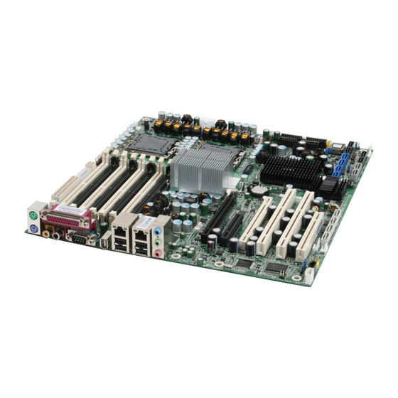
Page 7: Board Image
2.1– Board Image This picture is representative of the latest board revision available at the time of publishing. The board you receive may or may not look exactly like the above picture. http://www.tyan.com... -
Page 8: Block Diagram
2.2 – Block Diagram S5396 Block Diagram http://www.tyan.com... -
Page 9: Board Parts, Jumpers And Connectors
2.3 – Board Parts, Jumpers and Connectors This diagram is representative of the latest board revision available at the time of publishing. The board you receive may not look exactly like the above diagram. http://www.tyan.com... -
Page 10: Jumper Settings
Front Panel USB2.0 Connectors See Page19 CPU0FAN/CPU1FAN/ 4-pin FAN Header See Page20 FAN3/ FAN4 Jumper Legend OPEN - Jumper OFF Without jumper cover CLOSED - Jumper ON With jumper cover To indicate the location of pin-1 To indicate the location of pin-1 http://www.tyan.com... - Page 11 Normal Use jumper cap to close pin_2 and 3 for several (Default) seconds to clear the CMOS Replace the jumper cap to close pin_1 and pin_2 Reconnect the power supply to the AC source and power on the system http://www.tyan.com...
- Page 12 Use this jumper to disable the FWH write protect. (Default) Use this jumper to enable the FWH write protect. JP23: BIOS Recovery Jumper No BIOS recovery function (Default) BIOS will be forced into recovery. BIOS image will be loaded from floppy. http://www.tyan.com...
- Page 13 JP10 JP16 JP5: SAS Enable/Disable jumper Use this jumper to enable onboard SAS. (Default) Use this jumper to disable onboard SAS. http://www.tyan.com...
- Page 14 1-2 Close: Use this jumper to disable the PS/2 devices from waking up. 2-3 Close: Use this jumper to enable the waking up of the PS/2 devices. (Default) (Default) JP16: PCI-X Frequency Setting Jumper 1-2 close: 100MHz 2 close: 133MHz (Default) (Default) 2-3 close: 66MHz http://www.tyan.com...
- Page 15 LAN port JP20/JP21: LAN1/LAN2 Link and Active LED Header JP20/JP21 is for connecting an external LED to indicate LAN1/LAN2 LINK and ACTIVITY. The behavior of this LED is the same as LAN1/LAN2 RJ45 LED: Pin 1: LINK Pin 2: ACT http://www.tyan.com...
- Page 16 P7: CD IN Header CD_L CD_GND CD_GND CD_R P11: AUX IN Header AUX_L AUX_R http://www.tyan.com...
- Page 17 LED Interface Connector is used to connect some control or signal wires from motherboard to chassis, such as HDD LED, power LED, power button, and reset button. SPKR_OUT_L SLP_LED + PWR_LED +_0 SPKR_OUT_H PWR_LED +_1 3.3V MSG_LED SCSI_LED -_0 3.3V SCSI_LED -_1 HDD_LED - PWRBTN_N SLPBTN_N RESET_N http://www.tyan.com...
- Page 18 J33: 1394 Front Panel Header TPA0+ TPA0- TPB0+ TPB0- +12V +12V J3: SMDC CON25X2_M3291 For connection with Tyan Server Management Daughter Card (SMDC). The SMDC connector is compatible with only the Tyan M3291 (SMDC). http://www.tyan.com...
- Page 19 J84/J85: Front Panel USB 2.0 Connectors Use these two headers to connect the USB devices via the enclosed USB cable. CCR_SYSTEM_ON_L USB_CCR_VCC USB_CCR_VCC USB_CCR_DAT1_L USB_CCR_DAT2_L USB_CCR_DAT1_H USB_CCR_DAT2_H http://www.tyan.com...
- Page 20 CPU0FAN/ CPU1FAN/ FAN3/ FAN4: 4-pin FAN Header FAN1/FAN2/FAN3: Use these headers to connect the cooling fans to the motherboard to keep the system stable and reliable. FAN0/FAN4: Pin 1 Pin 2 Pin 3 Pin 4 Fan PWM (speed) +12V Tachometer Control http://www.tyan.com...
-
Page 21: Tips On Installing Motherboard In Chassis
If there are any studs missing, you will know right away since the motherboard will not be able to be securely installed. http://www.tyan.com... - Page 22 Some chassis’ include plastic studs instead of metal. Although the plastic studs are usable, TYAN recommends using metal studs with screws that will fasten the motherboard more securely in place. Below is a chart detailing what the most common motherboard studs look like and how they should be installed.
-
Page 23: Installing The Processor(S)
2.6 - Installing the Processor(s) Your S5396 supports the latest processor technologies from Intel. Check the TYAN website for latest processor support: http://www.tyan.com Processor Installation The processor should be installed carefully. Make sure you are wearing an antistatic strap and handle the processor as little as possible. - Page 24 Turn the board upside down and insert the heat sink spring mechanism as shown. The heat sink spring may be already pre-installed by the manufacturer. Turn the board the right way up again and screw the heat sink into place. Repeat this procedure for the second processor. http://www.tyan.com...
- Page 25 (which should already be attached to the heatsink) to the motherboard. The following diagram illustrates how to connect fans onto the motherboard. After you have finished installing all the fans you can connect your drives (hard drives, CD-ROM drives, etc) to the motherboard. http://www.tyan.com...
-
Page 26: Installing The Memory
Before installing memory, ensure that the memory you have is compatible with the motherboard and processor. Only DDR2-533/667 FB-DIMM modules are required. Check the TYAN Web site at: www.tyan.com for details of the type of memory recommended for your motherboard. -
Page 27: Memory Installation Procedure
Align the memory module with the socket. The memory module is keyed to fit only one way in the socket. Key slot Seat the module firmly into the socket by gently pressing down until it sits flush with the socket. The locking levers pop up into place. http://www.tyan.com... -
Page 28: Attaching Drive Cables
Connections for these drives are also very simple. There is no need to set Master/Slave jumpers on SATA drives. Tyan has supplied two SATA cables and one SATA power adapter. If you are in need of other cables or power adapters please contact your place of purchase. - Page 29 Attach first floppy drive (drive A:) to the end of the cable with the twist in it. Drive B: is usually connected to the next possible connector on the cable (the second or third connector after you install Drive A:). http://www.tyan.com...
-
Page 30: Installing Add-In Cards
ESB2 ESB2 ESB2 P_AD20 PCI_IRQ_ PCI_IRQ_ PCI_IRQ_ PCI_IRQ_ Onboard ESB2 ESB2 1394(U) P_AD21 PCI_IRQ_ YOU MUST ALWAYS unplug the power connector from the NOTE motherboard before performing system hardware changes. Otherwise you may damage the board and/or expansion device. http://www.tyan.com... -
Page 31: Connecting External Devices
The chart below illustrates the different LED states. 10/100/1000 Mbps LAN Link/Activity LED Scheme Left LED Right LED Link Green 10 Mbps Active Blinking Green Link Green Green 100 Mbps Active Blinking Green Green Link Green Yellow 1000 Mbps Active Blinking Green Yellow No Link http://www.tyan.com... -
Page 32: Installing The Power Supply
Connect the EPS 12V 2X2-pin power connector. Connect power cable to power supply and power outlet Note: If Slot6 (PCI-E X16 slot, the one closest to the memory slots) is used, PW2 4X1 pin IDE power connector must be plugged in) http://www.tyan.com... -
Page 33: Finishing Up
A 750W power is sufficient for systems without many devices (i.e. 1 hard drive, 1 optical drive, and 1 or 2 expansion cards) however a higher wattage solution may be needed if the system is fully loaded. Refer to the www.tyan.com website for further information. -
Page 34: Chapter 3: Bios Setup
Changes settings. 3.1.2 Getting Help Pressing [F1] will display a small help window that describes the appropriate keys to use and the possible selections for the highlighted item. To exit the Help Window, press [ESC] or the [F1] key again. http://www.tyan.com... -
Page 35: In Case Of Problems
NOTE: The following pages provide the details of BIOS menu. Please be noticed that the BIOS menu are continually changing due to the BIOS updating. The BIOS menu provided are the most updated ones when this manual is written. Please visit Tyan’s website at http://www.tyan.com for the information of BIOS updating. -
Page 36: Bios Main Menu
[Tab], [Shift-Tab], or [Enter] selects field. ↑↓ Help Select Item Change Values Setup Defaults ← → Exit Select Menu Enter Select Save and Exit Sub-Menu System Time / Date setup System Time: Adjusts the system clock. Hours (24hr. format) Minutes Seconds http://www.tyan.com... - Page 37 Ultra DMA Mode: here. CD-ROM = a CD-ROM drive is installed here. ATAPI Removable = removable disk drive is installed here. ↑↓ Help Select Item Change Values Setup Defaults ← → Exit Select Menu Enter Select Save and Exit Sub-Menu http://www.tyan.com...
- Page 38 The Auto option automatically determines the correct transfer rates. Standard / Fast PIO 1 / Fast PIO 2 / Fast PIO 3 / Fast PIO 4 / FPIO 3 / DMA 1 / FPIO 4 / DMA 2 Ultra DMA Mode Enables or disables Ultra DMA Mode. http://www.tyan.com...
-
Page 39: Memory Cache
This feature is only available when the system BIOS is shadowed. It enables or disables the caching of the system BIOS ROM at F0000h-FFFFFh via the L2 cache. This greatly speeds up accesses to the system BIOS. However, this http://www.tyan.com... - Page 40 These features allow you to control caching of C8000-CBFF/CC00-CFFF memory. Disabled / Write Through / Write Protect / Write Back Cahe D000-D3FF/Cahe D400-D7FF/Cache D800-DBFF/Cahe DC00-DFFF These features allow you to control caching of D000-D3FF/D400-D7FF/D800- D8FF/DC00-DFFF memory. Disabled / Write Through / Write Protect / Write Back http://www.tyan.com...
-
Page 41: Board Information
Advanced Security TPM State Power Boot Exit Board Information Item Specific Help Bios Version Bios Build Date Board Mfg Board ↑↓ Help Select Item Change Values Setup Defaults ← → Exit Select Menu Enter Select Save and Exit Sub-Menu http://www.tyan.com... -
Page 42: Advanced Menu
However, sometimes, the BIOS may not be able to detect the hardware changes. A serious resource conflict may occur and the operating system may not even boot as a result. This is where the Reset Configuration Data BIOS feature comes in. http://www.tyan.com... - Page 43 This feature is used to control the fan speed. Auto: Optimum temperature control at maximum CPU performance Full Speed: All fans are working at full speed. CPU Temp Reading This item is used to configure the CPU temperature reading. Auto / Diode / PECI http://www.tyan.com...
- Page 44 CPU0 Core voltage xxxx CPU1 VCore voltage xxxx CPU VTT xxxx VCC 1.5V xxxx VCC 3.3V xxxx VCC 5V xxxx VCC12V xxxx ↑↓ Help Select Item Change Values Setup Defaults ← → Exit Select Menu Enter Select Save and Exit Sub-Menu http://www.tyan.com...
-
Page 45: Bios Event Logging
When set to [Enabled], errors will be logged to BIOS event log. Disabled / Enabled View BIOS event log Press [Enter] to view BIOS event log Clear BIOS Event log When set to [Enabled], BIOS event log will be cleared. Disabled / Enabled http://www.tyan.com... -
Page 46: Advanced Chipset Control
4GB PCI Hole Granularity This feature is used to select the granularity of PCI hole for PCI resource. If MTRRs are not enough, we may use this option to reduce the MTRR occupation. 256MB / 512MB / 1.0GB / 2.0GB http://www.tyan.com... - Page 47 VT-d for Port0 (ESI) [Enabled] VT-d for Port1 [Enabled] VT-d for Port5 [Enabled] VT-d for Port9 [Enabled] VT-d for DMI Port [Enabled] ↑↓ Help Select Item Change Values Setup Defaults ← → Exit Select Menu Enter Select Save and Exit Sub-Menu http://www.tyan.com...
-
Page 48: Advanced Processor Options
Enable this only if you have an Intel Hyper Threading processor. Hyper-Threading Technology enables multi-threaded software applications to execute threads in parallel. Hyper-Threading Technology provides thread-level-parallelism (TLP) on each processor resulting in increased utilization of processor execution resources. As http://www.tyan.com... -
Page 49: Diskette Controller
Select Item Change Values Setup Defaults ← → Exit Select Menu Enter Select Save and Exit Sub-Menu Floppy Disk Controller This defines how the floppy disk controller is detected and configured. Disabled / Enabled / Auto / OS Controlled http://www.tyan.com... -
Page 50: Ata Controller
This item allows you to enable the SATA RAID functionality. Disabled / Enabled SATA AHCI Enable This item allows you to enable the SATA AHCI functionality. Disabled / Enabled If you do not want to install SATA AHCI driver, please set the SATA AHCI mode to Disabled. http://www.tyan.com... - Page 51 Select Menu Enter Select Save and Exit Sub-Menu Integrated SAS Interface This feature is used to enable the LSI SAS controller. Enabled / Disabled Option ROM Scan This feature is used to initialize the device expansion ROM. Enabled / Disabled http://www.tyan.com...
-
Page 52: Integrated Network Interface
Select Menu Enter Select Save and Exit Sub-Menu LAN Port0/1 These two features are used to configure the onboard LAN controllers. Enabled / Disabled Option ROM Scan This feature is used to initialize the device expansion ROM. Enabled / Disabled http://www.tyan.com... -
Page 53: Integrated Audio
3.3.10 Integrated 1394 PhoenixBIOS Setup Utility Main Advanced Security Power Boot Exit Integrated 1394 Item Specific Help Integrated 1394 [Enabled] ↑↓ Help Select Item Change Values Setup Defaults ← → Exit Select Menu Enter Select Save and Exit Sub-Menu http://www.tyan.com... -
Page 54: Integrated Usb
Enable or Disable all USB devices by setting item to the desired value. Enabled / Disabled Integrated USB2.0 Control USB 2.0 functionality through this Setup Item. Enabled / Disabled Legacy USB Support This option is used to enable the support for legacy USB. Enabled / Disabled http://www.tyan.com... - Page 55 - the ECP (Extended Capabilities Port) and EPP (Enhanced Parallel Port) modes. ECP uses the DMA protocol to achieve data transfer rates of up to 2.5 Mb/s and provides symmetric bidirectional communication. On the other hand, EPP uses existing parallel port signals to provide asymmetric bidirectional communication. http://www.tyan.com...
- Page 56 3 over DMA Channel 1 or vice versa. As long as either Channel 3 or Channel 1 is available for your parallel port to use, the parallel port will be able to function properly in ECP mode. DMA 3 http://www.tyan.com...
-
Page 57: Pci Configuration
PCI Device, Slot #2 PCI Device, Slot #3 PCI Device, Slot #4 PCI Device, Slot #5 PCI Device, Slot #6 ↑↓ Help Select Item Change Values Setup Defaults ← → Exit Select Menu Enter Select Save and Exit Sub-Menu http://www.tyan.com... - Page 58 Enabled / Disabled Latency Timer This feature is used to configure the minimum guaranteed time slice allotted for bus master in units of PCI bus clocks. Default / 0020h / 0040h / 0060h / 0080h / 00A0h / 00C0h / 00E0h http://www.tyan.com...
-
Page 59: Security Menu
Disabled / Enabled Write on Flexible Disks This item is used to configure the data written to floppy disk Unlocked: Data can be written to floppy disk Locked: No data can be written to floppy disk. Unlocked / Locked http://www.tyan.com... -
Page 60: Tpm State
PhoenixBIOS Setup Utility Main Advanced Security TPM State Power Boot Exit Item Specific Help Current TPM State Change TPM State ↑↓ Help Select Item Change Values Setup Defaults ← → Exit Select Menu Enter Select Save and Exit Sub-Menu http://www.tyan.com... -
Page 61: Power Menu
Disabled / Enabled After Power Failure This option is used to specify the mode of operation after the system recovers from a power loss. Stay off / Power on / Last State http://www.tyan.com... -
Page 62: Boot Menu
This feature is used to configure the boot message. Enabled: Displays OEM log instead of POST messages. Disabled: Displays normal POST messages Enabled / Disabled QuickBoot Mode This feature allows the system to skip certain tests while booting. Enabled / Disabled http://www.tyan.com... - Page 63 Select Menu Enter Select Save and Exit Sub-Menu The boot menu will list all bootable devices. Use <Enter> to expand or collapses devices with a ‘+’ or ‘-‘. Use <+> or <-> to arrange the priorities of all bootable devices. http://www.tyan.com...
-
Page 64: Exit Menu
Exit Discarding Changes This exits BIOS setup after discarding the changes made. Load Setup Defaults Loads the factory default values. Discard Changes Discards all changes made without exiting BIOS setup. Save Changes Saves all changes made without exiting BIOS. http://www.tyan.com... -
Page 65: Chapter 4: Diagnostics
The most common type of error is a memory error. Before contacting your vendor or TYAN Technical Support, be sure that you note as much as you can about the beep code length and order that you experience. Also, be ready with information regarding add-in cards, drives and O/S to speed the support process and come to a quicker solution. -
Page 66: Bios Post Code
1-4-1-1. RAM failure on data Setup System Management bits of high byte of memory bus Mode (SMM) area Code Beeps / Description Code Beeps / Description Display external L2 cache size Check key lock Load custom defaults (optional) Initialize Typematic rate http://www.tyan.com... - Page 67 Set Huge Segment Code Beeps / Description Code Beeps / Description Initialize Multi Processor Initialize Run Time Clock Initialize OEM special code Initialize video Initialize PIC and DMA Initialize System Management Mode Initialize Memory type Output one beep before boot http://www.tyan.com...
- Page 68 Initialize Memory size Boot to Mini DOS Shadow Boot Block Clear Huge Segment System memory test Boot to Full DOS Initialize interrupt vectors http://www.tyan.com...
-
Page 69: Appendix I: Smdc Information
IT Manager by providing multi-interfaces to access the hardware remotely and perform monitor, control and diagnose activities effectively. Tyan SMDC is not a peripheral card. Unlike regular peripheral card such as AGP card, Network card or SCSI card, SMDC does not require any hardware specific driver. As long as a standby power comes into the system, SMDC will begin looking after the system. - Page 70 Features of Tyan Server Management Monitor various system components remotely - such as fans, processor temperature, and more Remote power on and power off Console redirect -the ability to view system remotely Alert and error actions -such as audible beep, e-mail, power down and reboot...
-
Page 71: Appendix Ii: How To Make A Driver Diskette
Follow the steps below to make a driver diskette from the TYAN driver CD provided. Start the system and insert the TYAN CD into the CD-ROM drive to boot from CD. You will see the following menu. Then press [1] and [Enter] to boot the system to Tyan diskette maker. - Page 72 Follow the instruction on menu to insert a diskette and press [ENTER]. \Please insert a formatted diskette into A:/ and press [ENTER] Writing image to drive A: Track: 36 Hoad: 8 Sector: 1 Using "ESC" key to quit the Tyan diskette maker. The system will automatically restart. http://www.tyan.com...
-
Page 73: Glossary
SRAM instead of in the slow DRAM. Note that the cache is also much smaller than your regular memory: a typical cache size is 512KB, while you may have as much as 4GB of regular memory. http://www.tyan.com... - Page 74 EEPROM (Electrically Erasable Programmable ROM): also called Flash BIOS, is a ROM chip which can, unlike normal ROM, be updated. This allows you to keep up with changes in the BIOS programs without having to buy a new chip. TYAN’s BIOS updates can be found at http://www.tyan.com EMRL: Embedded RAID Logic.
- Page 75 Form factor: an industry term for the size, shape, power supply type, and external connector type of the Personal Computer Board (PCB) or motherboard. The standard form factors are the AT and ATX, although TYAN also makes some Baby-AT and ATX Footprint boards. Global timer: onboard hardware timer, such as the Real-Time Clock (RTC).
- Page 76 RAID level 1 also allows for faster access time and fault-tolerance, since either hard drive can be read at the same time. RAID level 0+1 is both striping and mirroring, providing fault-tolerance, striping, and faster access all at the same time. http://www.tyan.com...
- Page 77 Striping: see RAID UltraDMA-33/66/100: a fast version of the old DMA channel. UltraDMA is also called UltraATA. Without proper UltraDMA controller, your system cannot take advantage of higher data transfer rates of the new UltraDMA/UltraATA hard drives. http://www.tyan.com...
- Page 78 ZIF Socket (Zero Insertion Force socket): these sockets make it possible to insert CPUs without damaging the sensitive CPU pins. The CPU is lightly placed in an open ZIF socket, and a lever is pulled down. This shift the processor over and down, guiding into the board and locking it into place. http://www.tyan.com...
-
Page 79: Technical Support
Return Merchandise Authorization (RMA) number. The RMA number should be prominently displayed on the outside of the shipping carton and the package should be mailed prepaid. TYAN will pay to have the board shipped back to you. http://www.tyan.com... - Page 80 Danger of explosion if battery is incorrectly replaced. Replace only with the same or equivalent type recommended by manufacturer. Dispose of used battery according to manufacturer instructions and in accordance with your local regulations. Document #: D1930 - 100 http://www.tyan.com...