Table of Contents
Advertisement
///
Tempest i5100W
S5376
Version 1.0
Copyright
Copyright © TYAN Computer Corporation, 2008. All rights reserved. No part of this
manual may be reproduced or translated without prior written consent from TYAN
Computer Corp.
Trademark
All registered and unregistered trademarks and company names contained in this
manual are property of their respective owners including, but not limited to the
following.
TYAN, Tempest i5100W are trademarks of TYAN Computer Corporation.
Intel® 5100/5200/5400 Series and combinations thereof are trademarks of Intel
Corporation.
AMI, AMI BIOS are trademarks of AMI Technologies.
Microsoft, Windows are trademarks of Microsoft Corporation.
SuSE is a trademark of Novell.
IBM, PC, AT, and PS/2 are trademarks of IBM Corporation.
Notice
Information contained in this document is furnished by TYAN Computer Corporation
and has been reviewed for accuracy and reliability prior to printing. TYAN assumes
no liability whatsoever, and disclaims any express or implied warranty, relating to
sale and/or use of TYAN products including liability or warranties relating to fitness
for a particular purpose or merchantability. TYAN retains the right to make changes
to product descriptions and/or specifications at any time, without notice. In no event
will TYAN be held liable for any direct or indirect, incidental or consequential
damage, loss of use, loss of data or other malady resulting from errors or
inaccuracies of information contained in this document.
1
Advertisement
Table of Contents

Related Manuals for TYAN S5376


Summary of Contents for TYAN S5376
- Page 1 Tempest i5100W S5376 Version 1.0 Copyright Copyright © TYAN Computer Corporation, 2008. All rights reserved. No part of this manual may be reproduced or translated without prior written consent from TYAN Computer Corp. Trademark All registered and unregistered trademarks and company names contained in this manual are property of their respective owners including, but not limited to the following.
-
Page 2: Table Of Contents
Table of Contents Check the box contents! Chapter 1: Introduction Congratulations Hardware Specifications Chapter 2: Board Installation Board Image Block Diagram Board Parts, Jumpers and Connectors Tips on Installing Motherboard in Chassis Installing the Processor(s) Installing the Memory Attaching Drive Cables Installing Add-in Cards Installing Optional SO-DIMM Modules 2.10... -
Page 3: Check The Box Contents
6 x Serial ATA Cable 2 x USB2.0 cable 1x Serial Port Cable 1 x S5376 user’s manual 1 x S5376 Quick Reference guide 1 x TYAN driver CD 1 x I/O shield 2 x CPU Back Plane 1x ibutton (optional purchase, BTO, S5376WAG2NR5) If any of these items are missing, please contact your vendor/dealer for replacement before continuing with the installation process. - Page 4 NOTE...
-
Page 5: Chapter 1: Introduction
5100/5200/5400 Series processors and 48GB DDR2-533/667 DIMM memory, and featured with integrated Dual 82573V LAN controllers, built-in 32MB XGI Z9S video plus six SATA2 ports, the S5376 offers exceptional performance and versatile solution for your server / Workstation. Remember to visit TYAN’s Website at http://www.TYAN.com. There you can find information on all of TYAN’s products with FAQs, online manuals and BIOS... - Page 6 •Auto-configuration of hard disk •Two (2) COM ports (1 at rear, 1 types via cable) •Multiple boot options •Tyan 2x9 front panel pin header •48-bit LBA support •Tyan 2x6 front panel pin header for LAN LED and ID LED/Switch •2x7 pin Fan header Power •ATX 12V...
-
Page 7: Chapter 2: Board Installation
Chapter 2: Board Installation You are now ready to install your motherboard. The mounting hole pattern of the Tempest i5100W S5376 matches the SSI CEB specification. Before continuing with installation, confirm that your chassis supports an SSI CEB motherboard. How to install our products right… the first time The first thing you should do is reading this user’s manual. -
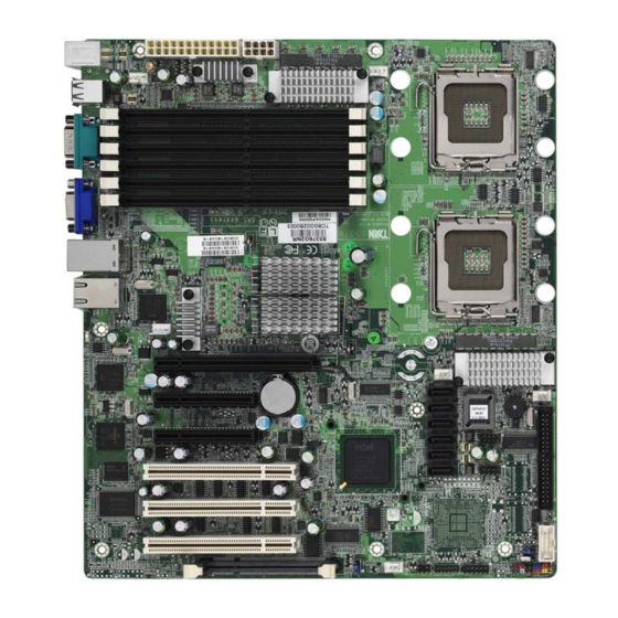
Page 8: Board Image
2.1- Board Image Tempest i5100W S5376WAG2NR/S5376WAG2NR5 This picture is representative of the latest board revision available at the time of publishing. The board you receive may or may not look exactly like the above picture. - Page 9 Tempest i5100W S5376G2NR This picture is representative of the latest board revision available at the time of publishing. The board you receive may or may not look exactly like the above picture.
-
Page 10: Block Diagram
2.2 - Block Diagram Tempest i5100W S5376WAG2NR/S5376WAG2NR5... - Page 11 Tempest i5100W S5376G2NR...
-
Page 12: Board Parts, Jumpers And Connectors
2.3 - Board Parts, Jumpers and Connectors This diagram is representative of the latest board revision available at the time of publishing. The board you receive may not look exactly like the above diagram. Jumper Legend OPEN - Jumper OFF, without jumper cover CLOSED –... - Page 13 FAN CONN (J12) Fan Board Header for Barebone SATA0~SATA5 Serial ATA Connector 24-pin Power Connector (EPS12V) 8-pin Power Connector (EPS12V) Aux. Power Connector for TYAN Riser Card (M2061) CPUFAN1/CPUFAN2/ 4-pin Fan Header with Tachometer FAN1/FAN2/FAN3 SAS 1068E Device ID Change Jumper...
- Page 14 SATA0 SATA1 SATA2 SATA3 SATA4 SATA5 USB3 USB2...
- Page 15 P1: Rear Audio Header (S5376WAG2NR and S5376WAG2NR5) Signal Signal MIC1_L_C MIC1_R_C MIC1_JD LINE1_L_C LINE1_R_C LINE1_JD FRONT_L_C FRONT_R_C FRONT_JD J1: Front Panel Audio Header (S5376WAG2NR and S5376WAG2NR5) Signal Signal MIC_L MIC_R PRESENT LINE_R MIC_JD LINE_L LINE_JD LCM (J5): LCM Header Signal Signal Link to MB V5 MB COM2 RX...
- Page 16 COM2 TYFP2 FAN CONN TYFP1...
- Page 17 COM2 (J22): COM2 Connector Signal Signal FAN CONN (J12): Fan Board Header for Barebone It is designed for barebone use only. Signal Signal CPU0-TACH SYS4-TACH CPU1-TACH SYS5-TACH FAN1-TACH SYS6-TACH FAN3-TACH SYS7-TACH FAN2-TACH SYS8-TACH HMO-FANPWM1 TYFP2 (J13): Front Panel Header 2 for Barebone It is designed for barebone use only.
- Page 18 FAN1 CPUFAN1 CPUFAN2 FAN3 FAN2...
- Page 19 FAN1/FAN2/FAN3/CPUFAN1/CPUFAN2: 4-pin Fan Header Use this header to connect the +1 2V Tach omete r cooling fan to your motherboard to PW M keep the system at optimum performance levels. Tachometer + 12 V JP1: SAS 1068E Device ID Change Jumper Pin 1-2 Closed: Device ID 58 (LSI IR RAID setting, S5376WAG2NR only) Pin 2-3 Closed: Device ID 59 (LSI Mega RAID setting,...
- Page 21 JP5: SAS 1068E Enable/Disable Jumper (S5376WAG2NR and S5376WAG2NR5) Pin 1-2 Closed: Enable (Default) Pin 2-3 Closed: Disable PW2: Aux. Power Connector for Riser Card (M2061) Signal +12V...
-
Page 22: Tips On Installing Motherboard In Chassis
Some chassis’ include plastic studs instead of metal. Although the plastic studs are usable, TYAN recommends using metal studs with screws that will fasten the motherboard more securely in place. Below is a chart detailing what the most common motherboard studs look like... -
Page 23: Installing The Processor(S)
2.5 - Installing the Processor(s) Your Tempest i5100W S5376 supports the latest processor technologies from Intel. Check the TYAN website for latest processor support: http://www.tyan.com Processor Installation (LGA771 Socket) The processor should be installed carefully. Make sure you are wearing an antistatic strap and handle the processor as little as possible. - Page 24 Lift the metal cover to expose the socket interior and place the socket in as shown. Pin 1 Close the cover and return the locking lever to its locked position. Repeat this procedure for the second processor socket. Turn the board upside down and insert the heat sink spring mechanism as shown.
- Page 25 Repeat this procedure for the second processor. Cooling Fan Installation After you have installed the processor, the heatsink should be installed to ensure that the processor runs efficiently and does not overheat. Use the heatsink supplied for best results. Follow these instructions to install the heatsink shown. Apply some (a little will work, more doesn’t equal better performance) thermal compound to the top of the processor.
-
Page 26: Installing The Memory
Before installing memory, ensure that the memory you have is compatible with the motherboard and processor. Only DDR2-667/533 DIMM modules are required. Check the TYAN Web site at: www.tyan.com for details of the type of memory recommended for your motherboard. - Page 27 The following chart outlines the suggested rules for populating memory. Single Channel Dual Channel Channel 0 Channel 1 Channel 0 & 1 DIMM1 DIMM2 DIMM3 DIMM4 DIMM5 DIMM6 DIMM1 DIMM2 DIMM3 DIMM4 DIMM5 DIMM6...
- Page 28 Memory Installation Procedure Follow these instructions to install memory modules into the Tempest i5100W S5376. Press the locking levers in the direction shown in the following illustration. Align the memory module with the socket. The memory module is keyed to fit only one way in the socket.
-
Page 29: Attaching Drive Cables
Connections for these drives are also very simple. There is no need to set Master/Slave jumpers on SATA drives. Tyan has supplied two SATA cables and one SATA power adapter. If you are in need of other cables or power adapters please contact your place of purchase. -
Page 30: Installing Add-In Cards
2.8 - Installing Add-In Cards Before installing add-in cards, it’s helpful to know if they are fully compatible with your motherboard. For this reason, we’ve provided the diagrams below, showing the slots that appear on your motherboard. 1 PCI-E x16 slot (w/ x16 bus) 2 PCI-E x8 slots (w/ x4 bus) 3 PCI 32/33MHz slots Simply find the appropriate slot for your add-in card and insert the card firmly. -
Page 31: Installing Optional So-Dimm Modules
The 200-pin vertical SO-DIMM connector can be used for TYAN M3295- 2/M3296 expansion card to provide such features as additional TYAN SMDC module support. For details of available expansions cards, visit the TYAN website at http://www.tyan.com. To install a SO-DIMM expansion card: Open the spring levers as shown. -
Page 32: Connecting External Devices
2.10 - Connecting External Devices The following diagram will detail the rear port stack for this S5376 motherboard: PS/2 Mouse/Keyboard LAN1 LAN3 LAN2 (IPMI) Serial Port VGA Port USB x 2 NOTE: Peripheral devices can be plugged straight into any of these ports but software may be required to complete the installation. -
Page 33: Installing The Power Supply
CPU(s). 1 x 24-pin 12V Power Connector (PW1) 1 x 8-pin 12V Power Connector (PW3) 1 x 4-pin 12V/5V Power Connector (PW2, aux. power supply for TYAN Riser Card M2061) Applying power to the board: Connect the 12V 8-pin power connector. - Page 34 NOTE...
-
Page 35: Chapter 3: Bios Setup
Chapter 3: BIOS Setup About the BIOS The BIOS is the basic input/output system, the firmware on the motherboard that enables your hardware to interface with your software. The BIOS determines what a computer can do without accessing programs from a disk. The BIOS contains all the code required to control the keyboard, display screen, disk drives, serial communications, and a number of miscellaneous functions. -
Page 36: Setup Basics
Chipset section unless you are absolutely sure of what you are doing. The Chipset defaults have been carefully chosen either by TYAN or your system manufacturer for best performance and reliability. Even a seemingly small change to the Chipset setup options may cause the system to become unstable or unusable. -
Page 37: Bios Main Menu
3.1 BIOS Main Menu The Main BIOS Menu is the first screen that you can navigate. The Main BIOS setup menu screen has two main frames. The left frame displays all the options that can be configured. "Grayed-out" options cannot be configured, options in blue can be changed. -
Page 38: Advanced Menu
3.2 Advanced Menu You can select any of the items in the left frame of the screen, such as Super I/O Configuration, to go to the sub menu for that item. You can display an Advanced BIOS Setup option by highlighting it using the <Arrow> keys. All Advanced BIOS Setup options are described in this section. -
Page 39: Cpu Configuration
3.2.1 CPU Configuration You can use this screen to view CPU Configuration Menu. Use the up and down arrow ( / ) keys to select an item. Use the Plus and Minus (+/-) keys to change the value of the selected option. The settings are described on the following pages. BIOS Setup Utility Main Advanced... - Page 40 Enabled Enable or disable the C1 C1E Support Enhanced mode Disabled When enabled, the processor's hardware prefetcher will be Enabled enabled and allowed to automatically prefetch data and Hardware Prefetcher code for the processor. When disabled, the processor's Disabled hardware prefetcher will be disabled.
- Page 41 3.2.2 IDE Configuration Sub-Menu You can use this screen to select options for the IDE Configuration Settings. Use the up and down <Arrow> keys to select an item. Use the <Plus> and <Minus> keys to change the value of the selected option. BIOS Setup Utility Main Advanced...
- Page 42 3.2.2.1 SATA0 ~ SATA5 Sub-Menu BIOS Setup Utility Main Advanced PCI/PnP Boot Security Chipset Exit SATA0 ← → Select Screen Device: Not Detected ↑↓ Select Item Change Option Tab Select Field Type [Auto] General Help LBA /Large Mode [Auto] F10 Save and Exit Block (Multi-Sector Transfer) [Auto] ESC Exit...
- Page 43 3.2.3 Super IO Configuration Sub-Menu You can use this screen to select options for the Super I/O settings. Use the up and down arrow ( / ) keys to select an item. Use the Plus and Minus (+/-) keys to change the value of the selected option BIOS Setup Utility Main...
- Page 44 3.2.4 USB Configuration Sub-Menu You can use this screen to view the USB Configuration Menu. Use the up and down arrow ( / ) keys to select an item. Use the Plus and Minus (+/-) keys to change the value of the selected option. The settings are described on the following pages.
- Page 45 3.2.4.1 USB Mass Storage Device Configuration Sub-Menu BIOS Setup Utility Main Advanced PCI/PnP Boot Security Chipset Exit USB Mass Storage Device Configuration ← → Select Screen USB Mass Storage Reset Delay [20 Sec] ↑↓ Select Item Device #1 USB Flash Disk Change Option Emulation Type [Auto]...
- Page 46 3.2.5 ACPI Configuration Sub-Menu Use this screen to select options for ACPI. Use the up and down arrow ( / ) keys to select an item. Use the Plus and Minus (+/-) keys to change the value of the selected option. A description of the selected item appears on the right side of the screen.
- Page 47 3.2.5.1 Advanced ACPI Configuration Sub-Menu BIOS Setup Utility Main Advanced PCI/PnP Boot Security Chipset Exit Advanced ACPI Configuration ← → Select Screen ACPI Version Features [ACPI v3.0] ↑↓ Select Item ACPI APIC support [Enabled] Change Option AMI OEMB table [Enabled] General Help Headless mode [Disabled]...
- Page 48 3.2.5.2 Chipset ACPI Configuration Sub-Menu BIOS Setup Utility Main Advanced PCI/PnP Boot Security Chipset Exit South Bridge ACPI Configuration ← → Select Screen ↑↓ Select Item Energy Lake Feature [Disabled] Change Option ACPI APIC SCI IRQ [Disabled] General Help F10 Save and Exit ESC Exit Feature Option...
- Page 49 3.2.6 AHCI Configuration Sub-Menu You can use this screen to view the AHCI Configuration Menu. Use the up and down arrow ( / ) keys to select an item. Use the Plus and Minus (+/-) keys to change the value of the selected option. The settings are described on the following pages.
- Page 50 3.2.6.1 AHCI Port0/Port1/Port2/Port3/Port4/Port5 Sub-Menu BIOS Setup Utility Main Advanced PCI/PnP Boot Security Chipset Exit AHCI Port0 ← → Select Screen Device: Not Detected ↑↓ Select Item Change Option General Help SATA Port0 [Auto] F10 Save and Exit S.M.A.R.T. [Enabled] ESC Exit Feature Option Description...
-
Page 51: Apm Configuration
3.2.7 APM Configuration BIOS Setup Utility Main Advanced PCI/PnP Boot Security Chipset Exit Enable or disable APM. APM Configuration ← → Select Screen Power Management/APM [Enabled] Video Power Down Mode [Suspend] ↑↓ Select Item Hard Disk Power Down Mode [Suspend] Change Option Suspend Time Out [Disabled]... - Page 52 87.5% 75.0% 62.5% Select the duty cycle in throttle mode Throttle Slow Clock Ratio 37.5% 12.5% MONITOR Keyboard & PS/2 Mouse Monitor KBC Ports 60/64 Ignore On/Off Go into On/Off, or Suspend when Power Button Mode Power Button is pressed. Suspend Enable/Disable RI to generate a wake Disabled...
- Page 53 3.2.8 Event Log Configuration Sub-Menu You can use this screen to view the Event Log Control Menu. This logs system events (such as CMOS clear) and writes the log into NVRAM. Use the up and down arrow ( / ) keys to select an item. Use the Plus and Minus (+/-) keys to change the value of the selected option.
- Page 54 3.2.9 Hardware Health Configuration Sub-Menu You can use this screen to view the Hardware Health Configuration Settings. Use the up and down arrow ( / ) keys to select an item. Use the Plus and Minus (+/-) keys to change the value of the selected option. The settings are described on the following pages.
- Page 55 3.2.9.1 Mainboard Voltages Report Sub-Menu BIOS Setup Utility Main Advanced PCI/PnP Boot Security Chipset Exit Board Voltages Event Monitoring CPU0 Vcore : x.xxx V CPU1 Vcore : x.xxx V : x.xxx V V3.3V : x.xxx V -12V : x.xxx V VBat : x.xxx V ←...
- Page 56 3.2.10 Remote Access Configuration Sub-Menu You can use this screen to view the Remote Access Configuration Menu. This feature allows access to the Server remotely via serial port. Use the up and down arrow ( / ) keys to select an item. Use the Plus and Minus (+/-) keys to change the value of the selected option.
- Page 57 None Select Flow Control for console Flow Control Hardware redirection. Software Disable: Turns off the redirection Disabled after POST Boot Loader: Redirection is active during POST Redirection After BIOS and during Boot Loader. Boot Loader POST Always: Redirection is always active. <Some OSs may not work if set to Always Always>...
-
Page 58: Pci Pnp Menu
3.3 PCI PnP Menu You can use this screen to view PnP (Plug & Play) BIOS Configuration Menu. This menu allows the user to configure how the BIOS assigns resources & resolves conflicts. Use the up and down arrow ( / ) keys to select an item. Use the Plus and Minus (+/-) keys to change the value of the selected option. - Page 59 Yes: assigns IRQ to PCI VGA card Allocate IRQ to PCI VGA if card requests IRQ. This is the default setting and should not be changed unless the Disabled VGA card manufacturer requires Palette Snooping to be Enabled. Palette Snooping Enabled: informs the PCI devices that an ISA graphics device is Enabled...
-
Page 60: Boot Menu
3.4 Boot Menu You can display Boot Setup option by highlighting it using the Arrow ( / ) keys and pressing Enter. The settings are described on the following pages. BIOS Setup Utility Main Advanced PCI/PnP Boot Security Chipset Exit Configures settings Boot Settings during System Boot. - Page 61 Feature Option Description Boot Settings Configuration Enabled This option allows user bypass BIOS Quick Boot self test during POST. Disabled Disabled: displays normal POST Disabled messages. Quiet Boot Enabled: displays OEM log instead of Enabled POST messages. Allows user to force BIOS/Option ROM Force BIOS Add On ROM Display of add-on cards to be displayed during...
- Page 62 3.4.2 Boot Device Priority Use this screen to select options for the Boot Device Priority. Use the up and down arrow ( / ) keys to select an item. Use the Plus and Minus (+/-) keys to change the value of the selected option. BIOS Setup Utility Main Advanced...
- Page 63 3.4.3 Removable Drives Use this screen to select options for the Removable Drives. Use the up and down arrow ( / ) keys to select an item. Use the Plus and Minus (+/-) keys to change the value of the selected option. BIOS Setup Utility Main Advanced...
-
Page 64: Security Menu
3.5 Security Menu The system can be configured so that all users must enter a password every time the system boots or when BIOS Setup is entered, using either the Supervisor password or User password. The Supervisor and User passwords activate two different levels of password security. -
Page 65: Chipset Menu
3.6 Chipset Menu This menu allows the user to customize functions of the AMD Chipsets. North Bridge configuration contains options for Memory & CPU settings. Select a menu by highlighting it using the Arrow ( / ) keys and pressing Enter. The settings are described on the following pages. - Page 66 3.6.1 North Bridge Configuration Sub-Menu This menu gives options for customizing North Bridge Chipset settings. Select a menu by highlighting it using the Arrow ( / ) keys and pressing Enter. The settings are described on the following pages. BIOS Setup Utility Main Advanced PCI/PnP...
- Page 67 Feature Option Description North Bridge Chipset Configuration Enabled Channel Dependent Channel dependent rank/DIMM sparing Sparing enabled/disabled Disabled Enabled Channel 0 Channel 0 enabled/disabled Disabled Disabled Channel Specific Enables rank/DIMM sparing feature Sparing Enabled Rank Interleaving Rank Interleaving setting Enabled Channel 1 Channel 1 enabled/disabled Disabled Disabled...
- Page 68 3.6.2 South Bridge Configuration Sub-Menu This menu gives options for customizing South Bridge Chipset settings. Select a menu by highlighting it using the Arrow ( / ) keys and pressing Enter. The settings are described on the following pages. BIOS Setup Utility Main Advanced PCI/PnP...
-
Page 69: Exit Menu
3.7 Exit Menu You can display an Exit BIOS Setup option by highlighting it Arrow ( / ) keys and pressing Enter. BIOS Setup Utility Main Advanced PCI/PnP Boot Security Chipset Exit Exit system setup after Exit Options saving the changes. F10 key can be used for Save Changes and Exit this operation. - Page 70 NOTE...
-
Page 71: Chapter 4: Diagnostics
BIOS flash failure, you must contact your dealer for a replacement BIOS. There are no exceptions. TYAN does not have a policy for replacing BIOS chips directly with end users. In no event will TYAN be held responsible for damages done by the end user. -
Page 72: Amibios Post Code
4.3 AMIBIOS Post Code The POST code checkpoints are the largest set of checkpoints during the BIOS pre- boot process. The following table describes the type of checkpoints that may occur during the POST portion of the BIOS: Checkpoint Description Disable NMI, Parity, video for EGA, and DMA controllers. - Page 73 Checkpoint Description Initializes different devices through DIM. See DIM Code Checkpoints section of document for more information. Initializes DMAC-1 & DMAC-2. Initialize RTC date/time. Test for total memory installed in the system. Also, Check for DEL or ESC keys to limit memory test. Display total memory in the system. Mid POST initialization of chipset registers.
- Page 74 NOTE...
-
Page 75: Appendix: Smdc Information
It enables any IT Manager by providing multi-interfaces to access the hardware remotely and perform monitor, control and diagnose activities effectively. Tyan SMDC is not a peripheral card. Unlike regular peripheral card such as AGP card, Network card or SCSI card, SMDC does not require any hardware specific driver. - Page 76 Features of Tyan Server Management Monitor various system components remotely - such as fans, processor temperature, and more Remote power on and power off Console redirect -the ability to view system remotely Alert and error actions -such as audible beep, e-mail, power down and reboot...
-
Page 77: Glossary
Glossary ACPI (Advanced Configuration and Power Interface): a power management specification that allows the operating system to control the amount of power distributed to the computer’s devices. Devices not in use can be turned off, reducing unnecessary power expenditure. AGP (Accelerated Graphics Port): a PCI-based interface which was designed specifically for demands of 3D graphics applications. - Page 78 Bus: a data pathway. The term is used especially to refer to the connection between the processor and system memory, and between the processor and PCI or ISA local buses. Bus mastering: allows peripheral devices and IDEs to access the system memory without going through the CPU (similar to DMA channels).
- Page 79 EEPROM (Electrically Erasable Programmable ROM): also called Flash BIOS, is a ROM chip which can, unlike normal ROM, be updated. This allows you to keep up with changes in the BIOS programs without having to buy a new chip. TYAN’s BIOS updates can be found at http://www.tyan.com ESCD (Extended System Configuration Data): a format for storing information about Plug-n-Play devices in the system BIOS.
- Page 80 Initial Program Load (IPL): a feature built into BBS-compliant devices, describing those devices as capable of loading and executing an OS, as well as being able to provide control back to the BIOS if the loading attempt fails. IPL: see Initial Program Load. IRQ (Interrupt Request): an electronic request that runs from a hardware device to the CPU.
- Page 81 PnP (Plug-n-Play): a design standard that has become ascendant in the industry. Plug-n-Play devices require little set-up to use. Novice end users can simply plug them into a computer that is running on a Plug-n-Play aware operating system (such as Windows 98), and go to work. Devices and operating systems that are not Plug-n-Play require you to reconfigure your system each time you add or change any part of your hardware.
- Page 82 Serial port: called as such because it transmits the eight bits of a byte of data along one wire, and receives data on another single wire (that is, the data is transmitted in serial form, one bit after another). SIMM (Single In-line Memory Module): formally the most common form of RAM for motherboards.
-
Page 83: Technical Support
Return Merchandise Authorization (RMA) number. The RMA number should be prominently displayed on the outside of the shipping carton and the package should be mailed prepaid. TYAN will pay to have the board shipped back to you. - Page 84 Notice for the USA Compliance Information Statement (Declaration of Conformity Procedure) DoC FCC Part 15: This device complies with part 15 of the FCC Rules Operation is subject to the following conditions: This device may not cause harmful interference, and This device must accept any interference received including interference that may cause undesired operation.
Need help?
Do you have a question about the S5376 and is the answer not in the manual?
Questions and answers