Table of Contents
Advertisement
Quick Links
Advertisement
Table of Contents

Summary of Contents for Venmar FAE125
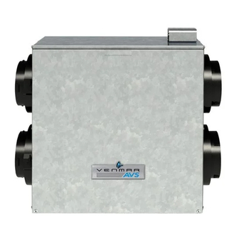
- Page 1 INSTALLATION AND USER MANUAL VB0134 FURNACE AIR EXCHANGER WITH HEAT RECOVERY MODELS FAE125 FAE 125M VFAE125 VFAE125M DDRESS OF YOUR INSTALLER INSTALLER: LEAVE THIS MANUAL WITH HOMEOWNER : 1-800-567-3855 USTOMER ERVICE HONE UMBER 09219 rev. 02...
- Page 2 OF A FURNACE AIR EXCHANGER WITH HEAT RECOVERY, NOR HELD RESPONSIBLE FOR SUBSEQUENT DAMAGE OR INCIDENT. During the period stated above, Venmar Ventilation Inc. or vänEE Canada will, at its option, repair or replace, without charge, any product or part which is found to be defective under normal use and service.
- Page 3 BOUT THESE NITS WARNING TO REDUCE THE RISK OF FIRE, ELECTRIC SHOCK, OR INJURY TO PERSON(S), OBSERVE THE FOLLOWING: This unit is intented for residential installation only. 2. Installation work and electrical wiring must be done by a qualified person(s) in accordance with all applicable codes and standards, including fire-rated construction codes and standards.
-
Page 4: Table Of Contents
ABLE OF ONTENTS ................... 5 ERVICE ARTS ................6-7 ECHNICAL 2.1 A ..................6 ISTRIBUTION 2.2 H ..................6 ECOVERY 2.3 D ................6 URING EATHER 2.4 D ....................7 IMENSIONS 2.5 S ................... 7 PECIFICATIONS 2.6 P ................. 7 ERFORMANCE HART ................ -
Page 5: Service Parts
ERVICE ARTS VL0037 FAE125 FAE125M ESCRIPTION VFAE125 VFAE125M 02253 ALANCING AMPER 02256 ORT FOR ALANCING AMPER 18620 ECOVERY 09214 ILTER 18619 SSEMBLY WITH SCREWS OTORIZED AMPER ASSEMBLY 18618 — WITH DAMPER SPRING 18682 RAIN ONNECTOR WITH 18683 CREWS PER KIT... -
Page 6: Technical Data
ECHNICAL 2.1 A ISTRIBUTION The figure below shows the air flows inside the units. XHAUST AIR RESH AIR FROM BUILDING FROM OUTSIDE RESH AIR XHAUST AIR TO BUILDING TO OUTSIDE VF0047 2.2 H ECOVERY This unit is equipped with a heat recovery core, specifically designed to reduce ventilation costs by recovering the heat energy from the exhaust air, and using that same heat energy to warm the fresh air being supplied. -
Page 7: Dimensions
IMENSIONS ” 22” * 6” typ. 19 ¹³/ ” ” 24¼” VK0069A * 22” height for FAE125M and VFAE125M models only. 2.5 S PECIFICATIONS FAE125, VFAE125 FAE125M, VFAE125M ODELS . (12.7 EIGHT (152 ORTS IAMETER INCHES RAIN IAMETER INCH NSTALLATION... -
Page 8: Typical Installations
YPICAL NSTALLATIONS The figure below illustrates a typical installation. The fresh air intake hood must be located at least 6’ away from the outdoor exhaust hood (measurement A), the fresh air from outside duct must be at least 6’ away from the furnace (measurement B) and the stale air from inside duct must be at least 18”... -
Page 9: Onnecting Ucts To The Nit
NSTALLATION CONT 4.2 C ONNECTING UCTS TO THE NSULATED FLEXIBLE DUCTS Use the following procedure for connecting the insulated flexible ducts to the ports on the unit (exhaust to outside and fresh air from outside). a) Pull back the insulation to expose the flexible duct. b) Connect the interior flexible duct to the opening using a duct tie. -
Page 10: Onnecting The Rain
NSTALLATION CONT 4.4 C ONNECTING THE RAIN Cut 2 sections of the plastic tube, at least 16” long, and attach them to each inner drain fitting, located under the unit. Join both short sections to the “T” junction and 16” 16”... - Page 11 ALANCING CONT Preliminary Stages for Balancing the Unit: Seal all the unit ductwork with duct tape. Close all windows and doors. Turn off all exhaust devices such as: range hood, dryer and bathroom fan(s). Make sure balancing dampers are fully opened (F and G in figure below). Choose appropriate locations for the 2 flow collars according to figure below: •...
-
Page 12: Wall Control
ALANCING CONT Balancing Procedure (cont'd): 5. If the furnace has a low speed option, select the low speed option and check if the fresh air flow and the stale air flow are still balanced. 6. Remove flow collars, reconnect the ducts and seal with duct tape. Write the required airflow information on a label and stick it near the unit for future reference: date, maximum speed airflows, your name and phone number and business address. -
Page 13: Maintenance
AINTENANCE WARNING We take great care to keep sharp edges to a minimum, but please be careful when handling components. Regular maintenance should be performed every 3 months. B Set the wall control to 80% (FAE125M or VFAE125M units only). C Remove both door lower screws no. -
Page 14: Troubleshooting
ROUBLESHOOTING If you think your unit is malfunctioning, check the following: ROBLEMS Nothing works • See if the transformer is plugged in. (models FAE125M • See if the transformer is receiving power and VFAE125M only). from the house circuit breaker. Condensation on windows •...


Need help?
Do you have a question about the FAE125 and is the answer not in the manual?
Questions and answers